EP2199482B1 - Isolation phonique pour murs de séparation mobiles - Google Patents
Isolation phonique pour murs de séparation mobiles Download PDFInfo
- Publication number
- EP2199482B1 EP2199482B1 EP20090176222 EP09176222A EP2199482B1 EP 2199482 B1 EP2199482 B1 EP 2199482B1 EP 20090176222 EP20090176222 EP 20090176222 EP 09176222 A EP09176222 A EP 09176222A EP 2199482 B1 EP2199482 B1 EP 2199482B1
- Authority
- EP
- European Patent Office
- Prior art keywords
- profile
- sound
- ceiling
- retaining
- retaining device
- Prior art date
- Legal status (The legal status is an assumption and is not a legal conclusion. Google has not performed a legal analysis and makes no representation as to the accuracy of the status listed.)
- Active
Links
Images




Classifications
-
- E—FIXED CONSTRUCTIONS
- E04—BUILDING
- E04B—GENERAL BUILDING CONSTRUCTIONS; WALLS, e.g. PARTITIONS; ROOFS; FLOORS; CEILINGS; INSULATION OR OTHER PROTECTION OF BUILDINGS
- E04B2/00—Walls, e.g. partitions, for buildings; Wall construction with regard to insulation; Connections specially adapted to walls
- E04B2/74—Removable non-load-bearing partitions; Partitions with a free upper edge
- E04B2/82—Removable non-load-bearing partitions; Partitions with a free upper edge characterised by the manner in which edges are connected to the building; Means therefor; Special details of easily-removable partitions as far as related to the connection with other parts of the building
- E04B2/827—Partitions constituted of sliding panels
-
- E—FIXED CONSTRUCTIONS
- E05—LOCKS; KEYS; WINDOW OR DOOR FITTINGS; SAFES
- E05D—HINGES OR SUSPENSION DEVICES FOR DOORS, WINDOWS OR WINGS
- E05D15/00—Suspension arrangements for wings
- E05D15/06—Suspension arrangements for wings for wings sliding horizontally more or less in their own plane
- E05D15/0621—Details, e.g. suspension or supporting guides
- E05D15/0626—Details, e.g. suspension or supporting guides for wings suspended at the top
- E05D15/0652—Tracks
-
- E—FIXED CONSTRUCTIONS
- E06—DOORS, WINDOWS, SHUTTERS, OR ROLLER BLINDS IN GENERAL; LADDERS
- E06B—FIXED OR MOVABLE CLOSURES FOR OPENINGS IN BUILDINGS, VEHICLES, FENCES OR LIKE ENCLOSURES IN GENERAL, e.g. DOORS, WINDOWS, BLINDS, GATES
- E06B7/00—Special arrangements or measures in connection with doors or windows
- E06B7/16—Sealing arrangements on wings or parts co-operating with the wings
- E06B7/18—Sealing arrangements on wings or parts co-operating with the wings by means of movable edgings, e.g. draught sealings additionally used for bolting, e.g. by spring force or with operating lever
-
- E—FIXED CONSTRUCTIONS
- E05—LOCKS; KEYS; WINDOW OR DOOR FITTINGS; SAFES
- E05Y—INDEXING SCHEME ASSOCIATED WITH SUBCLASSES E05D AND E05F, RELATING TO CONSTRUCTION ELEMENTS, ELECTRIC CONTROL, POWER SUPPLY, POWER SIGNAL OR TRANSMISSION, USER INTERFACES, MOUNTING OR COUPLING, DETAILS, ACCESSORIES, AUXILIARY OPERATIONS NOT OTHERWISE PROVIDED FOR, APPLICATION THEREOF
- E05Y2800/00—Details, accessories and auxiliary operations not otherwise provided for
- E05Y2800/40—Physical or chemical protection
- E05Y2800/422—Physical or chemical protection against vibration or noise
-
- E—FIXED CONSTRUCTIONS
- E05—LOCKS; KEYS; WINDOW OR DOOR FITTINGS; SAFES
- E05Y—INDEXING SCHEME ASSOCIATED WITH SUBCLASSES E05D AND E05F, RELATING TO CONSTRUCTION ELEMENTS, ELECTRIC CONTROL, POWER SUPPLY, POWER SIGNAL OR TRANSMISSION, USER INTERFACES, MOUNTING OR COUPLING, DETAILS, ACCESSORIES, AUXILIARY OPERATIONS NOT OTHERWISE PROVIDED FOR, APPLICATION THEREOF
- E05Y2900/00—Application of doors, windows, wings or fittings thereof
- E05Y2900/10—Application of doors, windows, wings or fittings thereof for buildings or parts thereof
- E05Y2900/13—Type of wing
- E05Y2900/142—Partition walls
Definitions
- the invention relates to a holding device for at least one mobile partition element, with at least one rail having at least one guide slot for guide rods of partition elements, wherein the holding device along the rail has receptacles for ceiling elements of a cover.
- the invention further relates to a guide system for at least one mobile partition element having a main arm with a main guide slot and at least one side arm with a Park Operationssschlitz, and a mobile partition wall element.
- Mobile wall systems also known as partition systems, are used for the variable subdivision of rooms.
- Known mobile wall systems have a guide rail, which is usually mounted in a suspended ceiling or suspended ceiling, and optionally a floor-mounted guide rail and flat mobile wall elements which are moved out of a rest position in which they take up little space and joined together to form a complete partition wall can be and vice versa.
- the individual mobile wall elements are clamped by means of movable elements, so-called Ausfahrtik duplex in the non-actuated state wholly or partially in the mobile wall element. In the extended state they protrude beyond the mobile wall element and are pressed against the ceiling or floor or ceiling rail or bottom rail.
- a transmission path is that an outer wall of a mobile partition wall element resonates as resonant membrane with sound waves from a room and transmits them via the frame or other solid components to which the outer wall is connected in the interior of the mobile partition element to the other outer wall.
- the second outer wall then serves as a loudspeaker diaphragm.
- This transmission path is similar to the system eardrum ossicle membrane of the human inner ear.
- the recorded sound can also be transmitted via the air in the interior of a mobile partition wall element to the second outer wall of the mobile partition wall element.
- Sound can also be generated by cracks between the mobile partition wall elements of a mobile partition wall system or between the elements and the ceiling or the floor or the walls of a mobile partition wall system Space penetrate.
- the said transmission paths for sound by mobile partition walls or mobile partition systems are independent of the materials used in the mobile partition elements. Common materials in this context are metals, wood or plastics or composites.
- Conventional holding devices for mobile partition wall elements comprise a rail in the form of, for example, a hollow profile with a central guide slot for guide rods of partition wall elements which are suspended on their upper side on a supporting ceiling.
- the supporting ceiling carries the weight of the mobile wall, as far as the mobile wall elements are not supported yet by means of extended Ausfahrtikmie on the ground.
- the rail profiles are laterally provided, for example, on their underside with inverted T-profiles, wherein on both sides in each case a horizontal arm of the T-profile protrudes laterally beyond a side wall of the rail profile.
- On the towering arm of the T-profile there are ceiling elements or panels of a supporting ceiling, so that the suspension ceiling or its ceiling panels or elements are substantially flush with the underside of the rail profile.
- the T-profiles thus form receptacles for the ceiling elements of the suspension ceiling.
- US 2001/0032424 A1 relates to a system for concealing guide rails of a mobile partition wall system, wherein a guide rail is directly and extensively connected to two other profiles, which has a support for suspended ceiling elements. In addition, these elements still have conditions for further insulation elements on both sides of the rail.
- GB 1 397 901 A relates to cover panels to sound-absorbing partition elements with a frame and cover panels, which are connected on both sides with the frame, and rigid intermediate layers, which are arranged between the frame and the cover panels.
- the partition wall elements each have on the top and bottom double extension strips, which are each extended together.
- the present invention has for its object to achieve an improved sound insulation for mobile wall systems, in particular sound transmission paths on the ceiling and the mobile wall elements themselves are prevented or mitigated.
- a holding device for at least one mobile partition element with at least one rail having at least one guide slot for guide rods of partition elements, wherein the holding device along the rail has receptacles for ceiling elements of a cover, wherein at least one sound insulation body is provided the along the rail a transmission of structure-borne sound, which is further developed in that the rail is arranged on at least one upper holder profile and at least a lower holder profile is designed as a receptacle for a ceiling element, wherein the at least one sound-absorbing body, the upper holder profile with the lower holder profile combines.
- “along the rail” in the context of the invention means that at no point along the rail structure-borne noise is transmitted uninsulated from one side of the holding device to the other side.
- the sound-absorbing body is aligned parallel to the rail.
- a receptacle for a ceiling element is also a support surface for a ceiling element or a system component which has such a support surface for a ceiling element.
- a sound-absorbing body is in the context of the invention, a body which consists at least substantially of a sound-absorbing material.
- the basic idea of the invention with regard to the holding device according to the invention is that in this way a sound insulation for structure-borne noise is generated, that is to say for sound which is transmitted and transmitted in solids.
- the structure-borne noise must pass through at least one sound-absorbing body on the way from a ceiling element, for example a suspended ceiling panel, through the retaining device to the next ceiling element.
- a ceiling element for example a suspended ceiling panel
- the sound-absorbing body is still arranged sound-insulating between the ceiling element and the rail or adjacent ceiling elements.
- the receptacle is designed as a sound-absorbing body.
- the essential parts of the corresponding system component consist of a sound-insulating material, so that the recording has no sound bridges with no or only slightly sound-absorbing materials for uninsulated sound transmissions.
- this also means that the receptacle is insulated from a ceiling element by means of a sound insulation body.
- the sound-absorbing body is preferably arranged between the rail and the at least one receptacle for a ceiling element.
- the sound-absorbing body preferably comprises a material with a low elastic modulus of less than 3 GPa, in particular less than 0.5 GPa, in particular less than 0.1 GPa, or consists at least essentially of such a material.
- the sound-absorbing body has a low modulus of elasticity which differs from the much higher moduli of elasticity of the adjacent components of the holding device and / or the supporting ceiling elements.
- the term elastic modulus is understood to mean the technical definition of the static modulus of elasticity.
- the modulus of elasticity is a measure of how much resistance a solid opposes to its deformation and determines the propagation properties for sound in the solid state. Thus, the propagation velocity of sound in solids and their acoustic characteristic impedance depends on the modulus of elasticity.
- the metals and hard plastics or woods usually used in mobile partitions have elastic moduli of more than 10 GPa.
- Sound-absorbing bodies according to the invention have a modulus of elasticity of less than 3 GPa, preferably less than 0.5 GPa, more preferably less than 0.1 GPa.
- particularly suitable materials are elastomers ("rubber") with moduli of elasticity between 0.01 and 0.1 GPa, polystyrene with elastic moduli between 0.001 and 0.01 GPa or plastics and acrylates, for example Plexiglas, with up to 3 GPa.
- Wood with vertical fibers or composite materials with correspondingly low moduli of elasticity are also suitable.
- the sound absorbing body "at least substantially" consists of such a material means in the present invention that the essential parts of a sound absorbing body consist of such a material, so that no sound bridges of materials with higher moduli of elasticity, on the structure-borne sound can be forwarded undamped or little steamed.
- the previously explained principle is applicable to all structural components of the holding device, by means of which adjacent parts can be decoupled.
- the rail profile itself provided it out Metal or a similarly good sound-conducting material is made, forms in each case a sound bridge.
- the sound-absorbing body comprises a sound-absorbing material or at least substantially consists of such a material.
- the sound insulation is thus based on a further, possibly alternative, principle, namely the dissipative sound absorption, ie the absorption or conversion of sound energy into heat energy.
- Many low modulus materials such as rubber, also provide dissipative sound absorption.
- Such materials have a complex modulus of elasticity, the real part of the modulus of elasticity being related to the above-described effect of sound insulation by reflection at phase boundaries, and the imaginary part of the modulus of elasticity to the dissipative sound insulation.
- the sound absorbing body "at least substantially" consists of such a material, so to understand that the essential parts of a sound absorbing body consist of such a material, so that no sound bridges of materials with less or Lack of dissipative sound insulation arise over the structure-borne sound can be forwarded undamped or little steamed.
- the holding device is further developed in that the rail is arranged on at least one upper holder profile and at least one lower holder profile is designed as a receptacle for a ceiling element, wherein the at least one sound insulation body connects the upper holder profile with the lower holder profile.
- the Ceiling elements of the rail or the rail profile by means of at least one sound-absorbing body decoupled.
- the underside of the rail profile is no longer flush with the underside of the ceiling elements.
- the damping body works in this case as a supporting element of the holding device.
- the holder profiles themselves are made of a rigid material, for example metal, for example aluminum.
- an upper holder profile and a lower holder profile are each connected to one another via a plurality of sound insulation bodies, wherein the sound insulation body, the upper holder profile and the lower holder profile enclose a cavity.
- the arrangement of several sound-absorbing body between the holder profiles ensures greater mechanical stability and thus for safe installation.
- the cavity is at least partially filled with a Dämmmasse.
- a Dämmmasse next to a turn rubber-elastic mass and any other heavy mass, such as cement, plastic filling, metal or the like suitable, which means that the heavy Dämmmasse is very difficult to vibrate in the cavity and thus sound bad of a ceiling element transmits to the rail profile.
- the cavity is designed to receive electrical cables.
- the interior of the rail profile, in which carriages of the partition wall elements are moved can be mechanically separated from the space in which electrical lines are guided. In this way, electrical lines even when mounting a holding device according to the invention be installed immediately, while otherwise would have to be postponed in a separate assembly step.
- the rail and the upper holder profile by means of a clip or locking mechanism with grooves and hooks are connected to each other.
- a clip or locking mechanism with grooves and hooks are connected to each other.
- different partition systems make different rail profiles necessary, for example, differ in height, but while the connection of the holding profile with different rails via a locking mechanism or clip mechanism is possible.
- the upper holder profile has at least one sealing lip for sealing against a ceiling element.
- the sealing lip fulfills both the task of mechanically stabilizing the ceiling element between the lower and the upper holder profile as well as by suitable choice of material, such as a rubber-elastic material to acoustically decouple the ceiling element of the upper holder profile.
- the guide slot is sealed by means of oppositely disposed sealing lips.
- the upper holder profile and / or the lower holder profile on a profile for holding a sealing lip.
- the sealing lips are preferably abutting hose profile lips or overlapping flat profile lips.
- the sealing lips are made of an elastic material, so that at a position at which opens a guide rod of a partition wall element in a carriage in the interior of the rail profile, the sealing lips release the space for the guide strands, but close again before and behind the guide rod by overlapping or hitting each other.
- the upper holder profile has a support surface for at least one insulation board, which is arranged in the installed state between a ceiling and a supporting ceiling.
- the cavity between the false ceiling and the load-bearing ceiling is also a good sound conductor, in which sound can propagate almost unhindered.
- the arrangement of insulation boards between the ceiling and the supporting ceiling along the upper holder profile or the rail profile also prevents in this cavity the propagation of sound waves from a subspace in the other subspace of divided by the mobile wall in two subspaces space.
- a guide system for at least one mobile partition element having a main arm with a main guide slot and at least one side arm with a Park Operationssschlitz, wherein both the main arm and the side arm according to the invention have holding devices.
- the side arms which in some cases are perpendicular to the main arm, generally serve to place the divider elements in a parking position which is occupied when the entire room is not to be divided by the mobile divider wall. In this case, the mobile partition wall elements stowed on the edge of the room.
- a sound insulation according to the invention is preferably realized.
- Advantageous materials for sound insulation bodies are elastomers, Styrofoam or softer plastics, in particular polyacrylic and / or polyethylene. These plastics have a particularly good sound insulation property. Sound insulation body made of the latter plastics can be produced particularly easily in an injection molding or continuous casting process.
- a space with a mobile wall system or a mobile partition wall is shown in perspective.
- the floor 50, side walls 51, 52 and the suspended ceiling 53 or suspended ceiling of the divided space are shown.
- the rear wall 54 can be seen.
- the mobile wall consists of mobile wall elements 61, 62, 63, 64, 65, which are suspended on guide rails 55.
- the elements 61 and 62 are already braced in their predetermined positions in the mobile wall between the floor 50 and ceiling 53.
- the mobile wall element 63 is in a position just before the connection with the mobile wall element 62. By means of a crank, the mobile wall element 63, vertically clamped between the floor 50 and ceiling 53.
- the mobile wall elements 64 and 65 are located on the right side in a parking position, which occupies little space. They are not clamped in the parking position between the ceiling 53 and floor 50, their Ausfahrbuch für sunk in the mobile wall elements 64, 65.
- a holding device 1 is shown, in which the mobile wall elements 61 to 65 are held.
- a side arm is shown with a holding device 2, in which the mobile wall elements can be 61 to 65 parked.
- a holding device is shown schematically in section.
- a rail profile 13 of a holding device for a mobile partition wall system attached on a supporting ceiling 10 by means of support rods 14, 14 '.
- the rail profile 13 is rectangular in cross-section and has at the bottom center a gap or slot through which a guide rod 16 of a partition wall element (not shown) is guided.
- the guide rod 16 opens into a carriage 15 with rollers 17 on the underside and lateral guide rollers 18, 18 ', which are arranged in perspective behind two vertical support members (without reference numerals).
- the T-profiles 12, 12 ' are formed as receptacles in the form of sound-absorbing bodies 12, 12'. This prevents that sound from the ceiling element 11 of the suspension ceiling on the T-profile 12, the rail section 13 and the T-profile 12 'penetrates directly into the ceiling element 11' of the suspension ceiling, if it would be forwarded without significant attenuation.
- Both the rail profile 13 and the T-pieces 12 are usually formed in the prior art of metal or other hard and sustainable material. Likewise, structure-borne noise from the load-bearing ceiling 10 can be transmitted essentially uninsulated to the ceiling elements 11, 11 '. This is with T-profiles 12, 12 'designed as sound-damping elements are likewise prevented.
- the T-profiles 12, 12 'in Fig. 2 also made of metal, but their bearing surfaces be provided with sound-absorbing bodies.
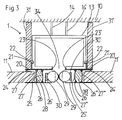
- a holding device 1 according to the invention is shown schematically in section.
- the carriage 15 and the guide rod 16 of a partition element not shown.
- insulating and supporting bodies 27, 27 ', 27 ", 27'" and the lower and upper holder profiles 20, 20 ', 25, 25' are two, in particular substantially rectangular, cavities formed in the example shown in FIG Fig. 3 with an insulating mass 28, 28 ', such as a cement or a plastic filling, are filled. It can also be introduced as a heavy mass metal.
- the insulation and support body 27 - 27 "' can be made in one piece with the upper holder profiles 20, 20' and optionally the insulation filling 28, 28 '.
- the rail profile 13 has a main guide slot 34, through which, as in Fig. 2 For example, shown, a guide rod 16 of a partition element can lead to a carriage 15.
- the lower holder profiles 25, 25 'each have a holding profile 30, 30' for insulating hoses or sealing tubes 29, 29 ', the in the normal state to touch (solid lines).
- Dashed lines illustrate the situation when a guide rod 16 (not shown, compare Fig. 2 ) would be present at the interface shown.
- the sealing hoses would then be deformed so that they would cling to the rod 16 and also in this way little or no sound can get into the rail section 13.
- FIGS. 4a and 4b an alternative type of sealing lips 33, 33 'for a guide slot 34 is shown. These are flat sealing lips 33, 33 ', which overlap in the middle of the guide slot 34. Both sealing lips 33, 33 'are fastened in clamping holder profiles 32, 32' by lower holder profiles 25, 25 ', wherein the clamping holder profiles 32, 32' describe a narrow opening into which the thickened ends of the flat sealing lips 33, 33 'are introduced that they can not be pulled out in a direction perpendicular to the guide slot 34.
- Fig. 4b the situation is illustrated that a guide rod 16 of a partition element passes through the slot 34. At this point, the upper, left-hand sealing lip 33 is deflected upwards and the lower, right-hand sealing lip 33 'is deflected downwards.
- a guide system according to the invention is shown, with a main arm and a main guide slot 34 which is expandable upward, and a side arm and a Park Operationssschlitz 35. Shown are also schematically the sealing lips 36, 36 'in the main arm and 36 “and 36"' in the side arm. Dashed lines schematically show the abutting edges or overlapping edges 37, 37 ', 37 "of the sealing lips 36, 36', 36", 36 "'.
- FIG. 6 is a schematic sectional view through a holding device according to the invention and a mobile partition wall element 41 is shown.
- the holding device 1 is shown in this case with the elements described above, in particular the rail profile 13 and ceiling elements 11 suspended therein.
- a carriage 15 is shown with the details described above.
- a cross member 44 is connected via a guide rod 16.
- About vertical decoupling rubber body 43, 43 'stored on the cross member 41 has two frames 42, 42'.
- the frames 42, 42 ' are connected to each other by means of a further, horizontally decoupling, rubber body 43 ".
- the left extension pressure shoe 46 is shown in the extended position and the right extension pressure shoe 46 'in a retracted position.
- At the top of the Ausfahrtiknic 46, 46 'rubber body for sound decoupling with the ceiling are arranged.
- the construction shown has several interfaces or interfaces and several dissipative sound-absorbing layers and interconnected, but decoupled by sound-absorbing elements components, resulting in a very strong insulation of the sound transmission. Not shown is the continuations of the partition wall element 41, which opens into a foot element with two Ausfahrtikmien. It may also be between the frame 42, 42 'preferably still be arranged inner walls, which represent further sound-reducing interfaces.
Landscapes
- Engineering & Computer Science (AREA)
- Civil Engineering (AREA)
- Structural Engineering (AREA)
- Architecture (AREA)
- Mechanical Engineering (AREA)
- Physics & Mathematics (AREA)
- Electromagnetism (AREA)
- Building Environments (AREA)
Claims (12)
- Dispositif de support (1,2) pour au moins un élément de mur de séparation mobile (41 ; 61-65), comprenant au moins un rail (13) avec au moins une fente de guidage (34, 35) pour des tiges de guidage (16) d'éléments de mur de séparation, le dispositif de support (1, 2) présentant, le long du rail (13), au moins un logement (12 ; 25, 25') pour au moins un élément de plafond (11, 11') d'un plafond de penderie (53), au moins un corps d'isolation phonique (12 ; 27-27"', 28, 28') étant prévu, qui amortit une transmission de bruit de structure le long du rail (13), caractérisé en ce que le rail (13) est agencé sur au moins un profilé de support supérieur (20, 20') et au moins un profilé de support inférieur (25, 25') est réalisé en tant que logement pour un élément de plafond (11, 11'), ledit au moins un corps d'isolation phonique (27-27"') reliant le profilé de support supérieur (20, 20') au profilé de support inférieur (25, 25').
- Dispositif de support (1, 2) selon la revendication 1, caractérisé en ce que le logement (12) est réalisé en tant que corps d'isolation phonique (12), qui est constitué au moins dans des parties substantielles d'un matériau insonorisant.
- Dispositif de support (1, 2) selon la revendication 1 ou la revendication 2, caractérisé en ce que le corps d'isolation phonique (27-27"', 28, 28') est agencé entre le rail (13) et au moins un logement (25, 25') pour un élément de plafond (11,11').
- Dispositif de support (1, 2) selon l'une des revendications 1 à 3, caractérisé en ce que le corps d'isolation phonique (27-27"', 28, 28') comprend un matériau d'un faible module d'élasticité de moins de 3 GPa, en généralement de moins de 0,5 GPa, en particulier de moins de 0,1 GPa, ou est constitué au moins dans des parties substantielles d'un tel matériau, en particulier en ce que le corps d'isolation phonique (12 ; 27-27''', 28, 28') comprend un matériau insonorisant ou est constitué au moins essentiellement d'un tel matériau.
- Dispositif de support (1, 2) selon l'une des revendications 1 à 4, caractérisé en ce qu'un profilé de support supérieur (20, 20') et un profilé de support inférieur (25, 25') sont à chaque fois reliés l'un à l'autre au moyen de plusieurs corps d'isolation phonique (27-27"'), les corps d'isolation phonique (27, 27' ; 27", 27"'), le profilé de support supérieur (20, 20') et le profilé de support inférieur (25, 25') délimitant un espace creux le long du rail (13), l'espace creux étant en particulier rempli au moins en partie d'une masse isolante et/ou est réalisé de façon à recevoir des câbles électriques.
- Dispositif de support (1, 2) selon l'une des revendications 1 à 5, caractérisé en ce que le rail (13) et le profilé de support supérieur (20, 20') peuvent être reliés l'un à l'autre au moyen d'un mécanisme à clip ou à encoche comprenant des rainures et des crochets.
- Dispositif de support (1, 2) selon l'une des revendications 1 à 6, caractérisé en ce que le profilé de support supérieur (20, 20') présente au moins une lèvre d'étanchéité (24, 24') permettant de réaliser l'étanchéité par rapport à un élément de plafond (11, 11').
- Dispositif de support (1, 2) selon l'une des revendications 1 à 7, caractérisé en ce que la fente de guidage (34, 35) est rendue étanche au moyen de lèvres d'étanchéité (29, 29' ; 33, 33' ; 36-36"') agencées en opposition.
- Dispositif de support (1, 2) selon la revendication 8, caractérisé en ce que le profilé de support supérieur (20, 20') et/ou le profilé de support inférieur (25, 25') présente un profilé (30, 30' ; 32, 32') destiné à supporter une lèvre d'étanchéité (29, 29' ; 33, 33' ; 36-36"').
- Dispositif de support selon la revendication 8 ou la revendication 9, caractérisé en ce que les lèvres d'étanchéité sont des lèvres profilées en forme de tuyau (29, 29') venant bout à bout l'une avec l'autre ou des lèvres profilées plates (33, 33') se chevauchant.
- Dispositif de support (1, 2) selon l'une des revendications 1 à 10, caractérisé en ce que le profilé de support supérieur (20, 20') présente une surface de réception pour au moins une plaque d'isolation (31, 31'), qui dans la position montée, est agencée entre un plafond de penderie (11, 11' ; 53) et un plafond portant (10).
- Système de guidage pour au moins un élément de mur de séparation mobile (41 ; 61-65) caractérisé en ce qu'il comprend un bras principal avec une fente de guidage principale (34) et au moins un bras latéral avec une fente de guidage d'arrêt (35), le bras principal et le bras latéral présentant l'un et l'autre des dispositifs de support (1, 2) selon l'une des revendications 1 à 11.
Applications Claiming Priority (1)
| Application Number | Priority Date | Filing Date | Title |
|---|---|---|---|
| DE200810061281 DE102008061281A1 (de) | 2008-12-11 | 2008-12-11 | Schalldämmung für mobile Trennwände |
Publications (3)
| Publication Number | Publication Date |
|---|---|
| EP2199482A2 EP2199482A2 (fr) | 2010-06-23 |
| EP2199482A3 EP2199482A3 (fr) | 2012-04-04 |
| EP2199482B1 true EP2199482B1 (fr) | 2013-11-06 |
Family
ID=42084466
Family Applications (1)
| Application Number | Title | Priority Date | Filing Date |
|---|---|---|---|
| EP20090176222 Active EP2199482B1 (fr) | 2008-12-11 | 2009-11-17 | Isolation phonique pour murs de séparation mobiles |
Country Status (2)
| Country | Link |
|---|---|
| EP (1) | EP2199482B1 (fr) |
| DE (1) | DE102008061281A1 (fr) |
Families Citing this family (2)
| Publication number | Priority date | Publication date | Assignee | Title |
|---|---|---|---|---|
| ES2529770T3 (es) * | 2011-05-20 | 2015-02-25 | Orchidées Constructions S.A. | Bastidor para paredes deslizantes |
| CN114737700B (zh) * | 2022-05-11 | 2024-04-12 | 浙江天元十杰装饰股份有限公司 | 一种隔音智能活动隔墙结构及其施工方法 |
Family Cites Families (13)
| Publication number | Priority date | Publication date | Assignee | Title |
|---|---|---|---|---|
| CH283660A (fr) * | 1949-06-04 | 1952-06-30 | Ferran Jose Pradell | Procédé de fabrication d'un élément de construction. |
| LU37880A1 (fr) * | 1958-11-17 | |||
| US3072975A (en) * | 1958-12-08 | 1963-01-15 | Richards Wilcox Mfg Co | Sealing mechanism for movable partition panels, doors and the like |
| US3121262A (en) * | 1960-07-28 | 1964-02-18 | Hyde Murphy Company | Sound insulating structure |
| DE2233059C3 (de) * | 1972-07-06 | 1975-11-20 | Fa. Justin Hueppe, 2900 Oldenburg | Versetzbare Trennwand mit mindestens einem schalldämmenden Trennwandelement |
| US3879799A (en) * | 1973-05-03 | 1975-04-29 | Hough Mfg Corp | Multidirectional suspension system for operable partitions |
| AT364128B (de) * | 1980-03-18 | 1981-09-25 | Brachmann Nagel Erich Dkfm Dr | Verschiebbare trennwand |
| NL8103258A (nl) * | 1981-07-08 | 1983-02-01 | Breedveld Beheer Bv | Geluiddempende uit panelen bestaande wandafscheiding. |
| US5042555A (en) * | 1990-10-01 | 1991-08-27 | Modernfold, Inc. | Floor-supported movable wall panel with height adjustment system |
| DE50100447D1 (de) * | 2000-03-29 | 2003-09-11 | Hawa Ag Mettmenstetten | Schallschutzvorrichtung für Systeme mit einem beweglichen Teil |
| CA2342564C (fr) * | 2000-04-03 | 2006-01-31 | Modernfold, Inc. | Systeme de dissimulation pour rails de murs mobiles |
| WO2004097133A2 (fr) * | 2003-05-01 | 2004-11-11 | Technische Universität München | Systeme de paroi mobile |
| US20060248826A1 (en) * | 2005-05-05 | 2006-11-09 | Owens N D | Soffit assembly for moveable wall system and removal tool therefor |
-
2008
- 2008-12-11 DE DE200810061281 patent/DE102008061281A1/de not_active Ceased
-
2009
- 2009-11-17 EP EP20090176222 patent/EP2199482B1/fr active Active
Also Published As
| Publication number | Publication date |
|---|---|
| EP2199482A2 (fr) | 2010-06-23 |
| DE102008061281A1 (de) | 2010-06-17 |
| EP2199482A3 (fr) | 2012-04-04 |
Similar Documents
| Publication | Publication Date | Title |
|---|---|---|
| DE202014103164U1 (de) | Aufprallablenkanordnung | |
| EP3095944B1 (fr) | Section d'ouvrage comprenant un cadre de fenetre | |
| DE2408028B2 (de) | Schallschluckplatte | |
| DE60031528T2 (de) | Isolierglas mit geschottetem akustischem wellenleiter | |
| DE202007017699U1 (de) | Trennwandelement | |
| DE102008051696A1 (de) | Schalltrennwandkonstruktion | |
| EP2199482B1 (fr) | Isolation phonique pour murs de séparation mobiles | |
| DE102010023726A1 (de) | Bauplatte sowie Verfahren und Vorrichtung zur Herstellung der Bauplatte | |
| WO2012083319A2 (fr) | Élément d'insonorisation | |
| EP2146016B1 (fr) | Amortissement phonique pour éléments de cloison de séparation mobile | |
| DE102013204999A1 (de) | Schaltafel mit Kunststoffschalhaut | |
| DE102012110369A1 (de) | Mehrschichtziegel und Verfahren zu dessen Herstellung | |
| AT509243B1 (de) | Schallschutzbauteil | |
| WO2010081680A1 (fr) | Boîte d'infiltration comprenant un logement pour un élément de stabilisation et système de rigoles comprenant plusieurs boîtes d'infiltration de ce type | |
| DE102010012202A1 (de) | Trennwandelement, insbesondere für eine mobile Trennwand, sowie entsprechende Trennwand | |
| AT513425B1 (de) | Schaltafel mit Kunststoffschalhaut | |
| EP3015612B1 (fr) | Élement de mur d'une construction ayant deux profiles et une plaque de mousse | |
| EP3984245B1 (fr) | Dispositif d'amortissement et système d'amortissement de haut-parleur pour un véhicule à moteur | |
| DE7508340U (de) | Vorgefertigte Lärmschutzwand | |
| DE202013102272U1 (de) | Schalungsstein zur Verbindung mit einer Betondecke | |
| WO2006119964A2 (fr) | Composant absorbant le son | |
| CH494870A (de) | Plattenförmiges, schalldämmendes, zweischalig aufgebautes Bauelement mit Schüttgutfüllung | |
| DE102007057478A1 (de) | Gebäude-Schalldämmmatte | |
| CH712803A2 (de) | Drahtgitterkorb und Abtrennvorrichtung mit einem Drahtgitterkorb. | |
| EP1605100A1 (fr) | Élément et écran insonorisant |
Legal Events
| Date | Code | Title | Description |
|---|---|---|---|
| PUAI | Public reference made under article 153(3) epc to a published international application that has entered the european phase |
Free format text: ORIGINAL CODE: 0009012 |
|
| AK | Designated contracting states |
Kind code of ref document: A2 Designated state(s): AT BE BG CH CY CZ DE DK EE ES FI FR GB GR HR HU IE IS IT LI LT LU LV MC MK MT NL NO PL PT RO SE SI SK SM TR |
|
| AX | Request for extension of the european patent |
Extension state: AL BA RS |
|
| RIC1 | Information provided on ipc code assigned before grant |
Ipc: E04B 2/82 20060101AFI20111130BHEP Ipc: E05D 15/06 20060101ALI20111130BHEP |
|
| PUAL | Search report despatched |
Free format text: ORIGINAL CODE: 0009013 |
|
| AK | Designated contracting states |
Kind code of ref document: A3 Designated state(s): AT BE BG CH CY CZ DE DK EE ES FI FR GB GR HR HU IE IS IT LI LT LU LV MC MK MT NL NO PL PT RO SE SI SK SM TR |
|
| AX | Request for extension of the european patent |
Extension state: AL BA RS |
|
| RIC1 | Information provided on ipc code assigned before grant |
Ipc: E06B 7/18 20060101ALI20120227BHEP Ipc: E04B 2/82 20060101AFI20120227BHEP Ipc: E06B 3/72 20060101ALI20120227BHEP Ipc: E06B 5/20 20060101ALI20120227BHEP Ipc: E05D 15/06 20060101ALI20120227BHEP |
|
| 17P | Request for examination filed |
Effective date: 20121002 |
|
| GRAP | Despatch of communication of intention to grant a patent |
Free format text: ORIGINAL CODE: EPIDOSNIGR1 |
|
| INTG | Intention to grant announced |
Effective date: 20130718 |
|
| GRAS | Grant fee paid |
Free format text: ORIGINAL CODE: EPIDOSNIGR3 |
|
| GRAA | (expected) grant |
Free format text: ORIGINAL CODE: 0009210 |
|
| AK | Designated contracting states |
Kind code of ref document: B1 Designated state(s): AT BE BG CH CY CZ DE DK EE ES FI FR GB GR HR HU IE IS IT LI LT LU LV MC MK MT NL NO PL PT RO SE SI SK SM TR |
|
| REG | Reference to a national code |
Ref country code: GB Ref legal event code: FG4D Free format text: NOT ENGLISH |
|
| REG | Reference to a national code |
Ref country code: CH Ref legal event code: EP |
|
| REG | Reference to a national code |
Ref country code: AT Ref legal event code: REF Ref document number: 639612 Country of ref document: AT Kind code of ref document: T Effective date: 20131215 |
|
| REG | Reference to a national code |
Ref country code: IE Ref legal event code: FG4D Free format text: LANGUAGE OF EP DOCUMENT: GERMAN |
|
| REG | Reference to a national code |
Ref country code: DE Ref legal event code: R096 Ref document number: 502009008282 Country of ref document: DE Effective date: 20140102 |
|
| REG | Reference to a national code |
Ref country code: NL Ref legal event code: T3 |
|
| REG | Reference to a national code |
Ref country code: SE Ref legal event code: TRGR |
|
| REG | Reference to a national code |
Ref country code: LT Ref legal event code: MG4D |
|
| PG25 | Lapsed in a contracting state [announced via postgrant information from national office to epo] |
Ref country code: FI Free format text: LAPSE BECAUSE OF FAILURE TO SUBMIT A TRANSLATION OF THE DESCRIPTION OR TO PAY THE FEE WITHIN THE PRESCRIBED TIME-LIMIT Effective date: 20131106 Ref country code: IS Free format text: LAPSE BECAUSE OF FAILURE TO SUBMIT A TRANSLATION OF THE DESCRIPTION OR TO PAY THE FEE WITHIN THE PRESCRIBED TIME-LIMIT Effective date: 20140306 Ref country code: NO Free format text: LAPSE BECAUSE OF FAILURE TO SUBMIT A TRANSLATION OF THE DESCRIPTION OR TO PAY THE FEE WITHIN THE PRESCRIBED TIME-LIMIT Effective date: 20140206 Ref country code: HR Free format text: LAPSE BECAUSE OF FAILURE TO SUBMIT A TRANSLATION OF THE DESCRIPTION OR TO PAY THE FEE WITHIN THE PRESCRIBED TIME-LIMIT Effective date: 20131106 Ref country code: LT Free format text: LAPSE BECAUSE OF FAILURE TO SUBMIT A TRANSLATION OF THE DESCRIPTION OR TO PAY THE FEE WITHIN THE PRESCRIBED TIME-LIMIT Effective date: 20131106 |
|
| PG25 | Lapsed in a contracting state [announced via postgrant information from national office to epo] |
Ref country code: ES Free format text: LAPSE BECAUSE OF FAILURE TO SUBMIT A TRANSLATION OF THE DESCRIPTION OR TO PAY THE FEE WITHIN THE PRESCRIBED TIME-LIMIT Effective date: 20131106 Ref country code: LV Free format text: LAPSE BECAUSE OF FAILURE TO SUBMIT A TRANSLATION OF THE DESCRIPTION OR TO PAY THE FEE WITHIN THE PRESCRIBED TIME-LIMIT Effective date: 20131106 |
|
| BERE | Be: lapsed |
Owner name: BECKER G.M.B.H. & CO. KG Effective date: 20131130 |
|
| PG25 | Lapsed in a contracting state [announced via postgrant information from national office to epo] |
Ref country code: PT Free format text: LAPSE BECAUSE OF FAILURE TO SUBMIT A TRANSLATION OF THE DESCRIPTION OR TO PAY THE FEE WITHIN THE PRESCRIBED TIME-LIMIT Effective date: 20140306 |
|
| REG | Reference to a national code |
Ref country code: CH Ref legal event code: PL |
|
| PG25 | Lapsed in a contracting state [announced via postgrant information from national office to epo] |
Ref country code: EE Free format text: LAPSE BECAUSE OF FAILURE TO SUBMIT A TRANSLATION OF THE DESCRIPTION OR TO PAY THE FEE WITHIN THE PRESCRIBED TIME-LIMIT Effective date: 20131106 Ref country code: LI Free format text: LAPSE BECAUSE OF NON-PAYMENT OF DUE FEES Effective date: 20131130 Ref country code: CH Free format text: LAPSE BECAUSE OF NON-PAYMENT OF DUE FEES Effective date: 20131130 |
|
| REG | Reference to a national code |
Ref country code: DE Ref legal event code: R097 Ref document number: 502009008282 Country of ref document: DE |
|
| REG | Reference to a national code |
Ref country code: IE Ref legal event code: MM4A |
|
| PG25 | Lapsed in a contracting state [announced via postgrant information from national office to epo] |
Ref country code: IT Free format text: LAPSE BECAUSE OF FAILURE TO SUBMIT A TRANSLATION OF THE DESCRIPTION OR TO PAY THE FEE WITHIN THE PRESCRIBED TIME-LIMIT Effective date: 20131106 Ref country code: RO Free format text: LAPSE BECAUSE OF FAILURE TO SUBMIT A TRANSLATION OF THE DESCRIPTION OR TO PAY THE FEE WITHIN THE PRESCRIBED TIME-LIMIT Effective date: 20131106 Ref country code: SK Free format text: LAPSE BECAUSE OF FAILURE TO SUBMIT A TRANSLATION OF THE DESCRIPTION OR TO PAY THE FEE WITHIN THE PRESCRIBED TIME-LIMIT Effective date: 20131106 Ref country code: MC Free format text: LAPSE BECAUSE OF FAILURE TO SUBMIT A TRANSLATION OF THE DESCRIPTION OR TO PAY THE FEE WITHIN THE PRESCRIBED TIME-LIMIT Effective date: 20131106 Ref country code: PL Free format text: LAPSE BECAUSE OF FAILURE TO SUBMIT A TRANSLATION OF THE DESCRIPTION OR TO PAY THE FEE WITHIN THE PRESCRIBED TIME-LIMIT Effective date: 20131106 |
|
| PLBE | No opposition filed within time limit |
Free format text: ORIGINAL CODE: 0009261 |
|
| STAA | Information on the status of an ep patent application or granted ep patent |
Free format text: STATUS: NO OPPOSITION FILED WITHIN TIME LIMIT |
|
| PG25 | Lapsed in a contracting state [announced via postgrant information from national office to epo] |
Ref country code: BE Free format text: LAPSE BECAUSE OF NON-PAYMENT OF DUE FEES Effective date: 20131130 Ref country code: DK Free format text: LAPSE BECAUSE OF FAILURE TO SUBMIT A TRANSLATION OF THE DESCRIPTION OR TO PAY THE FEE WITHIN THE PRESCRIBED TIME-LIMIT Effective date: 20131106 |
|
| 26N | No opposition filed |
Effective date: 20140807 |
|
| REG | Reference to a national code |
Ref country code: FR Ref legal event code: ST Effective date: 20140917 |
|
| PG25 | Lapsed in a contracting state [announced via postgrant information from national office to epo] |
Ref country code: IE Free format text: LAPSE BECAUSE OF NON-PAYMENT OF DUE FEES Effective date: 20131117 |
|
| REG | Reference to a national code |
Ref country code: DE Ref legal event code: R097 Ref document number: 502009008282 Country of ref document: DE Effective date: 20140807 |
|
| PG25 | Lapsed in a contracting state [announced via postgrant information from national office to epo] |
Ref country code: FR Free format text: LAPSE BECAUSE OF NON-PAYMENT OF DUE FEES Effective date: 20140106 |
|
| PG25 | Lapsed in a contracting state [announced via postgrant information from national office to epo] |
Ref country code: SI Free format text: LAPSE BECAUSE OF FAILURE TO SUBMIT A TRANSLATION OF THE DESCRIPTION OR TO PAY THE FEE WITHIN THE PRESCRIBED TIME-LIMIT Effective date: 20131106 |
|
| PG25 | Lapsed in a contracting state [announced via postgrant information from national office to epo] |
Ref country code: SM Free format text: LAPSE BECAUSE OF FAILURE TO SUBMIT A TRANSLATION OF THE DESCRIPTION OR TO PAY THE FEE WITHIN THE PRESCRIBED TIME-LIMIT Effective date: 20131106 |
|
| PG25 | Lapsed in a contracting state [announced via postgrant information from national office to epo] |
Ref country code: CY Free format text: LAPSE BECAUSE OF FAILURE TO SUBMIT A TRANSLATION OF THE DESCRIPTION OR TO PAY THE FEE WITHIN THE PRESCRIBED TIME-LIMIT Effective date: 20131106 Ref country code: TR Free format text: LAPSE BECAUSE OF FAILURE TO SUBMIT A TRANSLATION OF THE DESCRIPTION OR TO PAY THE FEE WITHIN THE PRESCRIBED TIME-LIMIT Effective date: 20131106 |
|
| PG25 | Lapsed in a contracting state [announced via postgrant information from national office to epo] |
Ref country code: MK Free format text: LAPSE BECAUSE OF FAILURE TO SUBMIT A TRANSLATION OF THE DESCRIPTION OR TO PAY THE FEE WITHIN THE PRESCRIBED TIME-LIMIT Effective date: 20131106 Ref country code: BG Free format text: LAPSE BECAUSE OF FAILURE TO SUBMIT A TRANSLATION OF THE DESCRIPTION OR TO PAY THE FEE WITHIN THE PRESCRIBED TIME-LIMIT Effective date: 20131106 Ref country code: LU Free format text: LAPSE BECAUSE OF NON-PAYMENT OF DUE FEES Effective date: 20131117 Ref country code: HU Free format text: LAPSE BECAUSE OF FAILURE TO SUBMIT A TRANSLATION OF THE DESCRIPTION OR TO PAY THE FEE WITHIN THE PRESCRIBED TIME-LIMIT; INVALID AB INITIO Effective date: 20091117 |
|
| PG25 | Lapsed in a contracting state [announced via postgrant information from national office to epo] |
Ref country code: GR Free format text: LAPSE BECAUSE OF NON-PAYMENT OF DUE FEES Effective date: 20131106 Ref country code: MT Free format text: LAPSE BECAUSE OF FAILURE TO SUBMIT A TRANSLATION OF THE DESCRIPTION OR TO PAY THE FEE WITHIN THE PRESCRIBED TIME-LIMIT Effective date: 20131106 |
|
| REG | Reference to a national code |
Ref country code: AT Ref legal event code: MM01 Ref document number: 639612 Country of ref document: AT Kind code of ref document: T Effective date: 20141117 |
|
| PG25 | Lapsed in a contracting state [announced via postgrant information from national office to epo] |
Ref country code: AT Free format text: LAPSE BECAUSE OF NON-PAYMENT OF DUE FEES Effective date: 20141117 |
|
| PG25 | Lapsed in a contracting state [announced via postgrant information from national office to epo] |
Ref country code: GR Free format text: LAPSE BECAUSE OF FAILURE TO SUBMIT A TRANSLATION OF THE DESCRIPTION OR TO PAY THE FEE WITHIN THE PRESCRIBED TIME-LIMIT Effective date: 20140207 |
|
| PGFP | Annual fee paid to national office [announced via postgrant information from national office to epo] |
Ref country code: SE Payment date: 20211123 Year of fee payment: 13 Ref country code: CZ Payment date: 20211108 Year of fee payment: 13 Ref country code: GB Payment date: 20211123 Year of fee payment: 13 |
|
| REG | Reference to a national code |
Ref country code: SE Ref legal event code: EUG |
|
| GBPC | Gb: european patent ceased through non-payment of renewal fee |
Effective date: 20221117 |
|
| PG25 | Lapsed in a contracting state [announced via postgrant information from national office to epo] |
Ref country code: CZ Free format text: LAPSE BECAUSE OF NON-PAYMENT OF DUE FEES Effective date: 20221117 |
|
| PG25 | Lapsed in a contracting state [announced via postgrant information from national office to epo] |
Ref country code: SE Free format text: LAPSE BECAUSE OF NON-PAYMENT OF DUE FEES Effective date: 20221118 |
|
| PG25 | Lapsed in a contracting state [announced via postgrant information from national office to epo] |
Ref country code: GB Free format text: LAPSE BECAUSE OF NON-PAYMENT OF DUE FEES Effective date: 20221117 |
|
| PGFP | Annual fee paid to national office [announced via postgrant information from national office to epo] |
Ref country code: NL Payment date: 20251119 Year of fee payment: 17 |
|
| PGFP | Annual fee paid to national office [announced via postgrant information from national office to epo] |
Ref country code: DE Payment date: 20251118 Year of fee payment: 17 |