EP2199501B1 - Bâtiment anti-intrusion - Google Patents
Bâtiment anti-intrusion Download PDFInfo
- Publication number
- EP2199501B1 EP2199501B1 EP08106015A EP08106015A EP2199501B1 EP 2199501 B1 EP2199501 B1 EP 2199501B1 EP 08106015 A EP08106015 A EP 08106015A EP 08106015 A EP08106015 A EP 08106015A EP 2199501 B1 EP2199501 B1 EP 2199501B1
- Authority
- EP
- European Patent Office
- Prior art keywords
- building
- blocking device
- actuating
- closure element
- blocking
- Prior art date
- Legal status (The legal status is an assumption and is not a legal conclusion. Google has not performed a legal analysis and makes no representation as to the accuracy of the status listed.)
- Not-in-force
Links
- 230000000903 blocking effect Effects 0.000 claims abstract description 60
- 230000005540 biological transmission Effects 0.000 claims description 15
- 238000012544 monitoring process Methods 0.000 claims 1
- 239000000853 adhesive Substances 0.000 description 8
- 230000001070 adhesive effect Effects 0.000 description 8
- 230000033001 locomotion Effects 0.000 description 7
- 230000004913 activation Effects 0.000 description 5
- 238000001514 detection method Methods 0.000 description 5
- 239000011521 glass Substances 0.000 description 4
- 238000010276 construction Methods 0.000 description 2
- 238000006073 displacement reaction Methods 0.000 description 2
- 229910052751 metal Inorganic materials 0.000 description 2
- 239000002184 metal Substances 0.000 description 2
- 238000000034 method Methods 0.000 description 2
- 125000006850 spacer group Chemical group 0.000 description 2
- 241000239290 Araneae Species 0.000 description 1
- 241000511343 Chondrostoma nasus Species 0.000 description 1
- 235000010678 Paulownia tomentosa Nutrition 0.000 description 1
- 240000002834 Paulownia tomentosa Species 0.000 description 1
- 229910000831 Steel Inorganic materials 0.000 description 1
- 229910052782 aluminium Inorganic materials 0.000 description 1
- XAGFODPZIPBFFR-UHFFFAOYSA-N aluminium Chemical compound [Al] XAGFODPZIPBFFR-UHFFFAOYSA-N 0.000 description 1
- 238000013475 authorization Methods 0.000 description 1
- 239000003302 ferromagnetic material Substances 0.000 description 1
- 230000004313 glare Effects 0.000 description 1
- 230000005291 magnetic effect Effects 0.000 description 1
- 238000004519 manufacturing process Methods 0.000 description 1
- 238000003801 milling Methods 0.000 description 1
- 210000000056 organ Anatomy 0.000 description 1
- 239000004033 plastic Substances 0.000 description 1
- 238000003825 pressing Methods 0.000 description 1
- 230000015607 signal release Effects 0.000 description 1
- 239000007787 solid Substances 0.000 description 1
- 239000010959 steel Substances 0.000 description 1
- 238000011144 upstream manufacturing Methods 0.000 description 1
Images


Classifications
-
- E—FIXED CONSTRUCTIONS
- E05—LOCKS; KEYS; WINDOW OR DOOR FITTINGS; SAFES
- E05B—LOCKS; ACCESSORIES THEREFOR; HANDCUFFS
- E05B47/00—Operating or controlling locks or other fastening devices by electric or magnetic means
- E05B47/06—Controlling mechanically-operated bolts by electro-magnetically-operated detents
- E05B47/0657—Controlling mechanically-operated bolts by electro-magnetically-operated detents by locking the handle, spindle, follower or the like
-
- E—FIXED CONSTRUCTIONS
- E05—LOCKS; KEYS; WINDOW OR DOOR FITTINGS; SAFES
- E05B—LOCKS; ACCESSORIES THEREFOR; HANDCUFFS
- E05B47/00—Operating or controlling locks or other fastening devices by electric or magnetic means
- E05B47/0001—Operating or controlling locks or other fastening devices by electric or magnetic means with electric actuators; Constructional features thereof
- E05B47/0002—Operating or controlling locks or other fastening devices by electric or magnetic means with electric actuators; Constructional features thereof with electromagnets
-
- E—FIXED CONSTRUCTIONS
- E05—LOCKS; KEYS; WINDOW OR DOOR FITTINGS; SAFES
- E05B—LOCKS; ACCESSORIES THEREFOR; HANDCUFFS
- E05B47/00—Operating or controlling locks or other fastening devices by electric or magnetic means
- E05B47/06—Controlling mechanically-operated bolts by electro-magnetically-operated detents
- E05B47/0607—Controlling mechanically-operated bolts by electro-magnetically-operated detents the detent moving pivotally or rotatively
-
- E—FIXED CONSTRUCTIONS
- E05—LOCKS; KEYS; WINDOW OR DOOR FITTINGS; SAFES
- E05B—LOCKS; ACCESSORIES THEREFOR; HANDCUFFS
- E05B65/00—Locks or fastenings for special use
- E05B65/10—Locks or fastenings for special use for panic or emergency doors
- E05B65/1046—Panic bars
- E05B65/106—Panic bars pivoting
- E05B65/1066—Panic bars pivoting the pivot axis being substantially parallel to the longitudinal axis of the bar
-
- E—FIXED CONSTRUCTIONS
- E05—LOCKS; KEYS; WINDOW OR DOOR FITTINGS; SAFES
- E05B—LOCKS; ACCESSORIES THEREFOR; HANDCUFFS
- E05B17/00—Accessories in connection with locks
- E05B17/04—Devices for coupling the turning cylinder of a single or a double cylinder lock with the bolt operating member
- E05B17/042—Devices for coupling the turning cylinder of a single or a double cylinder lock with the bolt operating member using toothed wheels or geared sectors
-
- E—FIXED CONSTRUCTIONS
- E05—LOCKS; KEYS; WINDOW OR DOOR FITTINGS; SAFES
- E05B—LOCKS; ACCESSORIES THEREFOR; HANDCUFFS
- E05B47/00—Operating or controlling locks or other fastening devices by electric or magnetic means
- E05B2047/0072—Operation
- E05B2047/0076—Current to lock only, i.e. "fail-safe"
-
- E—FIXED CONSTRUCTIONS
- E05—LOCKS; KEYS; WINDOW OR DOOR FITTINGS; SAFES
- E05B—LOCKS; ACCESSORIES THEREFOR; HANDCUFFS
- E05B47/00—Operating or controlling locks or other fastening devices by electric or magnetic means
- E05B2047/0084—Key or electric means; Emergency release
- E05B2047/0086—Emergency release, e.g. key or electromagnet
- E05B2047/0087—Electric spare devices, e.g. auxiliary batteries or capacitors for back up
-
- E—FIXED CONSTRUCTIONS
- E05—LOCKS; KEYS; WINDOW OR DOOR FITTINGS; SAFES
- E05B—LOCKS; ACCESSORIES THEREFOR; HANDCUFFS
- E05B47/00—Operating or controlling locks or other fastening devices by electric or magnetic means
- E05B47/0001—Operating or controlling locks or other fastening devices by electric or magnetic means with electric actuators; Constructional features thereof
- E05B47/0002—Operating or controlling locks or other fastening devices by electric or magnetic means with electric actuators; Constructional features thereof with electromagnets
- E05B47/0003—Operating or controlling locks or other fastening devices by electric or magnetic means with electric actuators; Constructional features thereof with electromagnets having a movable core
- E05B47/0004—Operating or controlling locks or other fastening devices by electric or magnetic means with electric actuators; Constructional features thereof with electromagnets having a movable core said core being linearly movable
-
- E—FIXED CONSTRUCTIONS
- E05—LOCKS; KEYS; WINDOW OR DOOR FITTINGS; SAFES
- E05B—LOCKS; ACCESSORIES THEREFOR; HANDCUFFS
- E05B47/00—Operating or controlling locks or other fastening devices by electric or magnetic means
- E05B47/0001—Operating or controlling locks or other fastening devices by electric or magnetic means with electric actuators; Constructional features thereof
- E05B47/0002—Operating or controlling locks or other fastening devices by electric or magnetic means with electric actuators; Constructional features thereof with electromagnets
- E05B47/0006—Operating or controlling locks or other fastening devices by electric or magnetic means with electric actuators; Constructional features thereof with electromagnets having a non-movable core; with permanent magnet
-
- E—FIXED CONSTRUCTIONS
- E05—LOCKS; KEYS; WINDOW OR DOOR FITTINGS; SAFES
- E05B—LOCKS; ACCESSORIES THEREFOR; HANDCUFFS
- E05B47/00—Operating or controlling locks or other fastening devices by electric or magnetic means
- E05B47/0046—Electric or magnetic means in the striker or on the frame; Operating or controlling the striker plate
- E05B47/0047—Striker rotating about an axis parallel to the wing edge
-
- E—FIXED CONSTRUCTIONS
- E05—LOCKS; KEYS; WINDOW OR DOOR FITTINGS; SAFES
- E05B—LOCKS; ACCESSORIES THEREFOR; HANDCUFFS
- E05B65/00—Locks or fastenings for special use
- E05B65/10—Locks or fastenings for special use for panic or emergency doors
- E05B65/1046—Panic bars
- E05B65/1053—Panic bars sliding towards and away form the door
-
- E—FIXED CONSTRUCTIONS
- E05—LOCKS; KEYS; WINDOW OR DOOR FITTINGS; SAFES
- E05C—BOLTS OR FASTENING DEVICES FOR WINGS, SPECIALLY FOR DOORS OR WINDOWS
- E05C7/00—Fastening devices specially adapted for two wings
- E05C7/04—Fastening devices specially adapted for two wings for wings which abut when closed
Definitions
- the invention relates to a building with at least one building opening and a closing element rotatably mounted on the building about at least one axis of rotation in the building opening, which closes the building opening in a closed position and allows passage of a person through the building opening in an open position
- the closing element in the building opening Closed position can be locked by means of locking elements against an unauthorized opening and the locking elements by means of an actuating element from a locking position into an unlocking position in which the closing element is rotatable in the open position, can be transferred by the actuating element from a basic position in which the locking elements in the locked position are transferred to an actuating position, in which the locking elements pass into the unlocked position, wherein the actuating element by means of a blocking egg tion in the basic position is blocked and the blocking device of a blocking state in which the actuating element is blocked, thereby in a release state can be transferred, that a triggering device emits a trigger signal.
- closure element in the context of the present application, all rotatably mounted closure organs can be understood, which in many cases to windows, doors, flaps or similar.
- the end elements may be plate-shaped or have a movable sash, in which a filling of glass, plastic or metal is used.
- At a soffit of the building opening can be a frame
- the actuating element may be all elements which are operated by the user legitimized for this purpose and are intended to act on the locking elements directly or indirectly via intermediate transmission elements and to transfer these from their locking position into the unlocking position and vice versa.
- the end elements which are particularly at risk in this regard are typically designed in a particularly solid and robust construction. This applies both to the end element and the frame present thereon (glare or wing frame), as well as the locking elements and the corresponding actuators.
- the security is increased by the fact that in the event of detection of a break-in attempt, for example by destroying an alarm spider or a detection of the burglar by means of a motion detector, additional locking elements are activated so that the door does not open even when the Panikentriegelungselements.
- the invention has for its object to provide a building with increased security against burglary, departure or outbreak, that is characterized on the one hand by a high level of security and on the other hand by the lowest possible manufacturing and construction costs.
- the blocking device has at least one swing door opener, which is concealed on or in a sash profile, wherein a coupled to the actuator transmission element is blocked by the case of the swing door opener.
- a swing door opener is used, which is preferably concealed on or in a sash profile on a side opposite the lock of the closing element side of the sash, wherein a coupled to the actuating element, preferably with the pressure bar or the swivel bar transmission element is blocked by the case of the swing door opener.
- Such swing door openers are available as standard and safety-tested components.
- the case of the swing door opener is spring-loaded and is extended in its basic position. Electromagnetically, the trap is blocked in this basic position, whereby holding forces of about 500 kg can be recorded. From this it is possible to achieve sufficiently large blocking forces for the actuating element.
- the document FR 2,865,491 discloses a swing door opener.
- the actuator is blocked to prevent unauthorized operation of the same.
- the ease of use is increased by the fact that the transfer of the blocking device from its blocking state in the release state in a remote controlled manner by means of a triggering device is possible, which can be arranged at a certain distance from the blocking device and also from the closing element itself and activation a trigger signal releases to remotely block the actuator.
- a triggering device In a state to be defined as a normal state according to the invention, therefore, the actuating element is not released, but the lifting of the blockage is executed only if an authorized person actually wishes to transfer the locking elements into their unlocked position to the closing element then bring into the open position.
- This request can be detected automatically by the triggering device or be voiced manually by means of a corresponding triggering element.
- the blocking device in its locked state as normal, for example, only during certain times, such as the night hours. In this time authorized uses of the terminating element are excluded, or so rare that the need to previously release a trigger signal for the transfer of the blocking device into the release state via the triggering device is not a real hindrance in practice.
- the blocking device normally be in the release state to increase comfort with frequent uses of the building completion, so that then the actuator is also usable without prior activation of the triggering device.
- the blocking device which is in any case already present in these cases, can also be used to bring the blocking device into its blocking state in the event of the detection of a break-in attempt.
- the blocking device is used in this case as an additional locking element, which is the teaching of DE 20 2007 015 667 U1 equivalent.
- the blocking device engages the actuating element itself or viewed in force flow from the user's hand to the locking elements "before" the actuator on.
- the present invention can be applied to panic doors.
- the actuating element is designed in this case as Panikentriegelungselement and arranged on an interior of a building facing side of the closure element.
- the occupied in case of panic operating position can be referred to in this case as emergency position.
- the triggering device may be arranged at a distance from the closing element trigger button, trigger switch (which may also be arranged in an alarm or monitoring center) of a person located in the interior of actuable or trigger sensor having a person located there recognizes and the trigger signal automatically dispenses.
- the blocking device preferably comprises an electromagnet which can be switched without current by means of the triggering device. The blocking of the actuating element is thus possible only when the coil of the electromagnet is energized. Should the power fail in an emergency, then the blocking device, which is equipped for this purpose with a corresponding spring element, automatically goes into the release state, so that the closing element can be opened after actuation of the actuating element.
- the panic unlocking element can be a swiveling bracket which is mounted so as to be pivotable about a horizontal axis and is articulated at both ends to a casement frame profile.
- a horizontally extending, in a direction perpendicular to the plane of the closing element relative to this displaceable and at both ends in each case attached to a casement profile pressure beam comes into question.
- the blocking of a panic pressure beam can be effected by means of an angular transmission element that is displaceable by an actuating linkage of the pressure beam in the horizontal direction and with a blocking leg a hidden opening in penetrates the sash profile and rests against the case of the swing door opener.
- the hidden opening for the blocking leg does not allow an attacker to recognize the operation and exact arrangement of the blocking device, so that the security is correspondingly large.
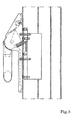
- the Figures 1 and 1a show an example, which is not an embodiment of the invention, but an example that facilitates the understanding of the invention.
- the Figures 1 and 1a show a section of a closing element 1 in the form of a panic door, which has a made of extruded aluminum profiles sash 2 with a filling of bulletproof glass and a frame, not shown, in which the sash 2 is rotatably mounted, wherein the frame in a building opening of a likewise not shown Building is anchored.
- actuating element 3 in the form of a Panikentriegelungs institutes in the form of a swivel bracket.
- the swivel bracket is at its two ends, each unwound at 45 ° (of which in FIG. 1 just one is shown) hinged to the sash 2.
- a bearing block 6 is attached for this purpose by means of screws 4 and a counter-plate 5.
- a not-shown, but known from the prior art actuating mechanism is set in motion, which acts on the nut of a lock 8 and also not shown locking elements extending from the sash in the frame inside extend, transferred to their unlocking position to swing in a panic case, the final element 1 from the locked, that is closed, state, that is, in this way to release an escape route out of the building.
- a holder 9 consisting of a flat steel is fastened to the bearing block 6 or the casement 2 with the aid of screws 10, one of which extends into the counterplate 5.
- a magnet 11 is attached at its free end with a screw.
- an adhesive element 12 in the form of a trapezoidal sheet is attached to the swivel bracket of the actuating element 3, which forms an adhesive surface 13 on its side facing the adhesive magnet 11.
- the holding magnet 11 is supplied with voltage via at least one of two feed lines, not shown, then the swivel bar is held on the holding magnet 11 via the holding element 12 such that the panic unlocking element is blocked in its basic position. It can therefore not be swung in the direction of arrow 7 on the closing element due to the very large adhesive force of unauthorized persons.
- the closing element 1 release an escape route
- the power supply to the holding magnet is completely interrupted, so that an actuation of the swivel bar, that is a pivoting in the direction of the arrow 7, is made possible again, whereby the locking elements of the closing element. 1 be disengaged.
- Restoration of the panic function may be either from a central office (eg after notification of a fire or other emergency in the building) or even by a person in need of an escape, for example by pressing a button or by detecting the person in an area be accomplished before the final element 1 using a motion detector.
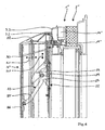
- a closure element 1 ' according to the Figures 2 and 3 Although also has a Panikentriegelungselement in the form of a swivel bracket as an actuating element 3.
- the blocking of the actuating element 3 takes place in this case, however, not by means of an adhesive magnet but by means of a standard component available as a swing door opener 14. This is in a by milling in the walls of the sash 2 'created interior of the sash 2' used and fixed there by means of screws.
- a pivotally mounted about an axis 15 on the bearing block 6 actuator 16 on the one hand has a receiving pin 17 for the tube designed as a swivel bracket and on the other hand connected to an actuating mechanism for unlocking the locking elements.
- the actuator 16 is still provided with a pressure piece 18 welded thereto, which cooperates with its free end with a latch 19 of the swing door opener 14 which is movably mounted in the direction of the double arrow 20 in the swing door opener 14 and by means of a spring in the direction of the swivel bar is biased.
- the pendulum door opener 14 is a known and tested or approved component, in which the case 19 by means of a magnet, not shown in the in FIG. 2 lock state shown is blocked, which in turn the Panikentriegelungselement in the form of the swivel bracket in the in FIG. 2 shown basic position is blocked.
- the swing door opener 14 which in turn is supplied with power via two supply lines, not shown, is disconnected from the power supply, then the latch 19 is free and the swivel bar can be pressed in the direction of the arrow 7 in order subsequently to open the in FIG. 3 represented occupy or emergency position, in which the locking elements of the closure element 1 'are in their unlocked position and thus the closure element 1' can be opened.
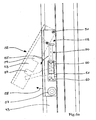
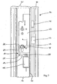
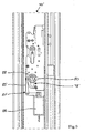
- FIGS. 4 and 5 show an even more alternative embodiment of the present invention a closing element 1 "also in the form of a panic door with a sash 2, wherein the actuating element 3" is listed in this case as a pressure bar, which is arranged in the direction of the double arrow 14 slidably in two end sides of the pressure bar and there with the wing frame 2 "connected bearing elements 22 is mounted.
- the pressure beam is provided on the one hand with a rocking lever 23, which is rotatably mounted on a bearing block 24 fixedly connected to the end element 1.
- a first arm 25 of the rocking lever 23 is pivotally mounted in a receiving element 26 of the pressure beam second arm 27 of the rocker arm 23, cooperates with a detail in detail not explained and consisting of a plurality of levers transmission mechanism 28, which is known from the prior art and ensures that upon actuation of the pressure bar, the latches of the closing element 1 "on a locknut unlocked.
- the second arm 27 also acts on an angular transmission element 30, which is displaceably mounted on the casement 2 "in the direction of the double arrow 31.
- the transmission element 30 has a blocking leg 32 which has an opening concealed in the bearing element 22 penetrates an outer sash profile 33 and abuts against a latch 19 "of a swing door opener 2", which is inserted through a cutout in the outer sash 33. In the swing door opener 14 "is powered and therefore blocked, neither the trap 19 "Still the transmission element 30 are moved, so that the pressure bar is locked in its normal position.
- FIG. 5 shows the emergency or operating position of the pressure bar, in which this by a distance 34 with respect to the in FIG. 4 shown basic position is shifted.
- the transmission element 30 is correspondingly displaced by the path 35 onto the swing door opener 14 "and has displaced the latch 19" into the swing door opener 14 ", since the actuating linkage 28 has likewise carried out its actuating movements during the displacement of the pressure bar unlocked and the final element 1 "can be opened.
- FIGS. 6 . 6a and 6b show another example not belonging to the invention of a closing element 40, which is an actuating wing of a two-leaf door, which is mounted in a common frame 41.
- the door also includes a wing, which forms a second end element 42 in addition to the control wing.
- Both end elements 40 and 42 each have a sash 43 and 44 and an existing armored glass filling 45 and 46th
- the aerofoil has a conventional pusher 47 which acts on a concealed by a shield 48 lock which is actuated by means of a lock cylinder 49.
- the pusher 47 may be designed as Panikentriegelungselement, which would then create an escape route through the active leaf.
- the pusher can also be blocked as an actuator by means of a separate blocking device to improve the burglar resistance in this case.
- the control wing is provided with an actuating element 50 in the form of a pivotally mounted on the sash frame 43 handle. Pressed over the handle, not visible locking elements cause in their locking position an engagement between the sash frame 43 and the frame 41. If the handle in the in the FIG. 6 dashed position shown pivoted, the control wing is unlocked, so that the pedestrian wing, which is connected only via locking elements with the control wing, also becomes free. Both wings can thus after opening the Panikentriegelungselements in the form of the pivotable handle to the outside, that is in the direction of escape, be swung.
- the actuator 50 in the form of the handle is by means of a blocking device in the form of a pivotable stop, in the in FIG. 6a Blockable with a solid line shown basic position.
- the pivotable stop is formed by a folded and pivotable about an axis 51 mounted plate 52.
- the plate 52 has in cross-section parallel to the plane of the fillings 45 and 46 of the two wings extending support leg 53 and at an angle of 90 ° thereto extending stop leg 54.
- the latter serves to pivotal movement of the handle in the direction of arrow 55th to prevent what happens because the stop leg is within a pivoting range 56 of the handle.
- the slight possibility of movement of the handle up to a contact with the stop leg 54 does not allow unlocking of the locking elements of the control wing.
- the plate 52 is in the FIG. 6a blocked by solid lines drawn blocking position with the help of a held in a profile of the sash 43 magnet 43.
- the magnetic clamp 57 pulls the ferromagnetic material consisting of sheet metal 52 with great force to the sash 43, so that such a large frictional force arises that a pivoting movement of the sheet in the in FIG. 6a dashed position shown is suppressed. With the blocking of the plate 52 and thus the handle is blocked.
- the sheet 52 can be pivoted away in the direction of the arrow 58 upon actuation of the handle and thus the handle in the dashed position according to FIG. 6a be brought in which both the control wing and the pedestrian wings are aufdrückbar to the outside.
- the plate 52 is provided with two cutouts 59, the spacer plates 60, which are arranged below a bearing block 61 of the actuating element 50, to be omitted when the plate 52 in the in FIG. 6a represented by solid lines blocking position.
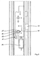
- FIGS. 7 and 8th show another not belonging to the invention example of a closure element 70 in the form of a door, comprising a sash 71 and a fixedly connected to the building frame 72.
- a lock 73 is installed in the sash and indeed in a cavity 74 of a sash profile 75.
- the known from the prior art lock 73 has a latch 76 and a latch 77 on.
- the latch 77 can be closed in a known manner with the aid of a lock cylinder 78.
- a shaft 79 of the lock cylinder 78 is provided in a known manner with a nose 80, which serves to drive an actuating mechanism for the latch 77.
- a blocking device for the actuating element in the form of the lock cylinder 78 comprises a pawl 81, which is mounted pivotally about an axis 82 in the sash profile 75.
- the pawl 81 has a in FIG. 7 on the nose 80 of the lock cylinder 78 supporting the blocking arm 83 and a right angle thereto arranged drive arm 84 which is pivotally coupled to a push rod 85 of an electromagnet 86.
- the pawl 81 is in the in FIG. 7 locked state shown. If the power supply to the solenoid 86 is interrupted, the armature and thus also the push rod 85 of the electromagnet by spring bias in the in FIG. 8 shown transferred upper position, which is why the pawl 81, the in FIG. 8 shown release position occupies.
- the blocking arm 83 of the pawl 81 is pivoted out of the marked by a line 87 rotation of the nose 80 in this state, so that the lock cylinder 78 and thus the latch 77 is normally actuated.
- FIGS. 7 and 8th very similar.
Landscapes
- Physics & Mathematics (AREA)
- Electromagnetism (AREA)
- Business, Economics & Management (AREA)
- Emergency Management (AREA)
- Power-Operated Mechanisms For Wings (AREA)
- Building Environments (AREA)
- Glass Compositions (AREA)
- Closing And Opening Devices For Wings, And Checks For Wings (AREA)
Claims (7)
- Bâtiment avec au moins une ouverture de bâtiment et un élément de fermeture (1', 1") logé sur le bâtiment en étant rotatif dans l'ouverture de bâtiment autour d'au moins un axe de rotation, qui dans une position de fermeture ferme l'ouverture de bâtiment et dans une position d'ouverture permet le passage d'une personne à travers l'ouverture du bâtiment , dans la position de fermeture, l'élément de fermeture (1', 1 ") étant verrouillable dans la position de fermeture contre une ouverture non autorisée au moyen d'éléments de verrouillage et les éléments de verrouillage étant susceptibles d'être amenés au moyen d'un élément de manoeuvre (3, 3") d'une position de verrouillage dans une position de déverrouillage dans laquelle l'élément de fermeture (1', 1 ") est susceptible de tourner dans la position d'ouverture, en ce qu'on amène l'élément de manoeuvre (3, 3") d'une position de base dans laquelle les éléments de verrouillage se trouvent dans la position de verrouillage dans une position de manoeuvre, dans laquelle les éléments de verrouillage passent dans la position de déverrouillage, l'élément de manoeuvre (3, 3") étant susceptible d'être bloqué dans la position de base au moyen d'un dispositif de blocage et le dispositif de blocage étant susceptible d'être amené de ce fait d'un état de fermeture, dans lequel l'élément de manoeuvre (3, 3") est bloqué dans un état de libération, en ce qu'un dispositif de déclenchement délivre un signal de déclenchement, caractérisé en ce que le dispositif de blocage comporte au moins un ouvre-porte pour porte battante (14, 14"), qui est disposé en étant recouvert sur ou dans un profilé de l'encadrement du battant, un élément de transmission (30) couplé à l'élément de manoeuvre (3, 3") étant susceptible d'être bloqué par le loquet (19, 19") de l'ouvre-porte pour porte battante (14, 14").
- Bâtiment selon la revendication 1, caractérisé en ce que l'élément de manoeuvre (3, 3") est un élément de déverrouillage anti-panique et en ce qu'il est disposé sur un côté de l'élément de fermeture (1', 1") qui fait face à un espace intérieur du bâtiment et en ce que la position de manoeuvre est une position d'urgence adoptée en cas de panique.
- Bâtiment selon la revendication 1 ou 2, caractérisé en ce que le dispositif de déclenchement comporte une touche de déclenchement, un interrupteur de déclenchement ou un capteur de déclenchement disposé à une distance de l'élément de fermeture qui est susceptible d'être manoeuvré par une personne se trouvant dans l'espace intérieur ou dans une centrale de supervision ou qui détecte une personne qui s'y trouve et en ce que le dispositif de blocage comporte un électroaimant qui est commutable en hors tension au moyen du dispositif de déclenchement.
- Bâtiment selon la revendication 2, caractérisé en ce que l'élément de déverrouillage anti-panique qui est disposé sur l'élément de fermeture (1', 1 ") est un étrier pivotant logé de sorte à pouvoir pivoter autour d'un axe horizontal et fixé de façon articulée par chacune de ses deux extrémités sur un profilé de l'encadrement du battant ou une barre de pression, s'étendant à l'horizontale, dans une direction à la perpendiculaire du plan de l'élément de fermeture, en étant déplaçable par rapport à ce dernier et fixé par chacune de ses deux extrémités sur un profilé de l'encadrement du battant.
- Bâtiment selon l'une quelconque des revendications 1 à 4, caractérisé en ce que l'ouvre-porte pour porte battante (14, 14") est disposé sur un côté de l'encadrement du battant (2', 2") qui est opposé à un verrou de l'élément de fermeture (1', 1 ").
- Bâtiment selon la revendication 4 et le cas échéant selon la revendication 5, caractérisé par un élément de transmission (30) de forme angulaire, qui est déplaçable en direction horizontale par une tringle de manoeuvre (28) de la barre de pression et qui par une branche de blocage (32) traverse une ouverture cachée dans l'encadrement du battant (33) et qui est adjacent au loquet de l'ouvre-porte pour porte battante (14").
- Bâtiment selon l'une quelconque des revendications 1 à 6, caractérisé par au moins deux lignes d'alimentation séparées vers l'électroaimant, qui se séparent sur le dispositif de blocage, convergent à une distance physique et ne se réunissent que directement à l'avant du dispositif de déclenchement.
Priority Applications (4)
| Application Number | Priority Date | Filing Date | Title |
|---|---|---|---|
| AT08106015T ATE499499T1 (de) | 2008-12-19 | 2008-12-19 | Einbruchsicheres gebäude |
| DE502008002697T DE502008002697D1 (de) | 2008-12-19 | 2008-12-19 | Einbruchsicheres Gebäude |
| EP08106015A EP2199501B1 (fr) | 2008-12-19 | 2008-12-19 | Bâtiment anti-intrusion |
| DE202008017989U DE202008017989U1 (de) | 2008-12-19 | 2008-12-19 | Einbruchsicheres Gebäude |
Applications Claiming Priority (1)
| Application Number | Priority Date | Filing Date | Title |
|---|---|---|---|
| EP08106015A EP2199501B1 (fr) | 2008-12-19 | 2008-12-19 | Bâtiment anti-intrusion |
Publications (2)
| Publication Number | Publication Date |
|---|---|
| EP2199501A1 EP2199501A1 (fr) | 2010-06-23 |
| EP2199501B1 true EP2199501B1 (fr) | 2011-02-23 |
Family
ID=40640332
Family Applications (1)
| Application Number | Title | Priority Date | Filing Date |
|---|---|---|---|
| EP08106015A Not-in-force EP2199501B1 (fr) | 2008-12-19 | 2008-12-19 | Bâtiment anti-intrusion |
Country Status (3)
| Country | Link |
|---|---|
| EP (1) | EP2199501B1 (fr) |
| AT (1) | ATE499499T1 (fr) |
| DE (2) | DE202008017989U1 (fr) |
Families Citing this family (5)
| Publication number | Priority date | Publication date | Assignee | Title |
|---|---|---|---|---|
| EP2348172B1 (fr) | 2010-01-25 | 2017-12-20 | BKS GmbH | Dispositif de déverrouillage |
| DE102010001195B4 (de) * | 2010-01-25 | 2015-05-13 | Bks Gmbh | Entriegelungsvorrichtung |
| EP2594723B1 (fr) * | 2011-11-16 | 2014-10-15 | Sälzer GmbH | Porte de sécurité conçue de manière résistante aux effractions |
| FR3134836B1 (fr) * | 2022-04-21 | 2024-05-31 | Cogelec | Système d’actionnement d’un mécanisme à pêne |
| FR3134837B1 (fr) * | 2022-04-21 | 2024-05-24 | Cogelec | Système d’actionnement d’un mécanisme à pêne |
Citations (1)
| Publication number | Priority date | Publication date | Assignee | Title |
|---|---|---|---|---|
| FR2865491A1 (fr) * | 2004-01-28 | 2005-07-29 | Procofi | Serrure electromagnetique a pene escamotable pour porte battante |
Family Cites Families (8)
| Publication number | Priority date | Publication date | Assignee | Title |
|---|---|---|---|---|
| DE3032086C2 (de) * | 1980-08-26 | 1983-08-11 | Scovill Sicherheitseinrichtungen Gmbh, 5620 Velbert | Türschloßbeschlag |
| US4384738A (en) * | 1980-10-16 | 1983-05-24 | Kidde, Inc. | Exit device with lock down mechanism |
| FR2572116B2 (fr) * | 1984-10-19 | 1988-09-30 | Leplat Robert | Dispositif de verrouillage et deverrouillage a distance, notamment pour barre anti-panique |
| DE8705383U1 (de) * | 1987-04-10 | 1987-08-13 | Bks Gmbh, 42549 Velbert | Elektromagnetisch verriegelbarer Drehhebel |
| GB2225371A (en) * | 1988-07-22 | 1990-05-30 | Dennis Paul Rowlett | Key and lock |
| US5823582A (en) * | 1995-08-24 | 1998-10-20 | Harrow Products, Inc. | Electromagnetically-managed latching exit bar |
| DE202007015666U1 (de) * | 2007-11-08 | 2008-02-07 | Sälzer Sicherheitstechnik GmbH | Gebäudeabschluss in einbruchhemmender Ausführung |
| DE202007015667U1 (de) | 2007-11-08 | 2008-04-03 | Sälzer Sicherheitstechnik GmbH | Gebäudeabschluss mit Panik-Entriegelungselement in einbruchhemmender Ausführung |
-
2008
- 2008-12-19 EP EP08106015A patent/EP2199501B1/fr not_active Not-in-force
- 2008-12-19 DE DE202008017989U patent/DE202008017989U1/de not_active Expired - Lifetime
- 2008-12-19 AT AT08106015T patent/ATE499499T1/de active
- 2008-12-19 DE DE502008002697T patent/DE502008002697D1/de active Active
Patent Citations (1)
| Publication number | Priority date | Publication date | Assignee | Title |
|---|---|---|---|---|
| FR2865491A1 (fr) * | 2004-01-28 | 2005-07-29 | Procofi | Serrure electromagnetique a pene escamotable pour porte battante |
Also Published As
| Publication number | Publication date |
|---|---|
| DE502008002697D1 (de) | 2011-04-07 |
| ATE499499T1 (de) | 2011-03-15 |
| EP2199501A1 (fr) | 2010-06-23 |
| DE202008017989U1 (de) | 2011-03-03 |
Similar Documents
| Publication | Publication Date | Title |
|---|---|---|
| EP0744002B1 (fr) | Systeme de verrouillage declencheur d'alarme pour la zone de fermeture et/ou de charniere d'une porte ou d'une fenetre a acces protege | |
| EP3832055B1 (fr) | Unité de verrouillage pour une installation de verrouillage d'une porte | |
| DE2940811A1 (de) | Sicherheitstuer fuer personen | |
| DE3032086A1 (de) | Panikschloss | |
| EP1944446B1 (fr) | Dispositif destiné à fermer des fenêtres ou des portes | |
| DE2611359A1 (de) | Treibstangenverschluss, insbesondere fuer zweifluegelige feuerschutztueren | |
| EP2199501B1 (fr) | Bâtiment anti-intrusion | |
| DE202016009122U1 (de) | Schwenkantrieb zum Überführen eines kipp- und/oder schwenkbaren Fensterflügels in eine Lüftungsstellung | |
| EP2058460B1 (fr) | Dispositif de verrouillage anti-effraction pour batiment | |
| WO2008031528A2 (fr) | Système de fermeture et d'ouverture pour la sécurisation d'un battant de porte pivotant dans une ouverture de bâtiment à l'encontre d'une ouverture non autorisée | |
| DE3050356C2 (de) | Panikschloß | |
| EP1066444A1 (fr) | Porte a double battant, notamment porte coupe-feu | |
| EP0858541B1 (fr) | Dispositif de verrouillage | |
| EP2385196B1 (fr) | Serrure | |
| EP2348172B1 (fr) | Dispositif de déverrouillage | |
| EP2309082B1 (fr) | Dispositif de surveillance de porte | |
| DE4322622C1 (de) | Entriegelungsvorrichtung für eine zweiflügelige, einen Stand- und Gangflügel umfassende Tür | |
| EP1321610B1 (fr) | Porte pivotante | |
| DE3737151C2 (de) | Verriegelungseinrichtung für eine zweiflügelige Tür | |
| EP1067270B1 (fr) | Dispositif de verrouillage pour un volet d'une ouverture de bâtiment, notamment pour un volet roulant | |
| DE19857432B4 (de) | Schließeinrichtung für Gebäudetüren oder Gebäudefenster | |
| WO2007104295A1 (fr) | Serrure pour une porte de maison ou d'appartement | |
| EP1961895A2 (fr) | Ferrure de porte | |
| DE10337593B4 (de) | Tor, insbesondere für Garagen | |
| EP0759493B1 (fr) | Porte à deux vantaux |
Legal Events
| Date | Code | Title | Description |
|---|---|---|---|
| PUAI | Public reference made under article 153(3) epc to a published international application that has entered the european phase |
Free format text: ORIGINAL CODE: 0009012 |
|
| 17P | Request for examination filed |
Effective date: 20090910 |
|
| AK | Designated contracting states |
Kind code of ref document: A1 Designated state(s): AT BE BG CH CY CZ DE DK EE ES FI FR GB GR HR HU IE IS IT LI LT LU LV MC MT NL NO PL PT RO SE SI SK TR |
|
| AX | Request for extension of the european patent |
Extension state: AL BA MK RS |
|
| RTI1 | Title (correction) |
Free format text: BUILDING SECURED AGAINST BREAK-IN |
|
| GRAP | Despatch of communication of intention to grant a patent |
Free format text: ORIGINAL CODE: EPIDOSNIGR1 |
|
| GRAS | Grant fee paid |
Free format text: ORIGINAL CODE: EPIDOSNIGR3 |
|
| GRAA | (expected) grant |
Free format text: ORIGINAL CODE: 0009210 |
|
| AK | Designated contracting states |
Kind code of ref document: B1 Designated state(s): AT BE BG CH CY CZ DE DK EE ES FI FR GB GR HR HU IE IS IT LI LT LU LV MC MT NL NO PL PT RO SE SI SK TR |
|
| REG | Reference to a national code |
Ref country code: GB Ref legal event code: FG4D Free format text: NOT ENGLISH |
|
| REG | Reference to a national code |
Ref country code: CH Ref legal event code: EP |
|
| AKX | Designation fees paid |
Designated state(s): AT BE BG CH CY CZ DE DK EE ES FI FR GB GR HR HU IE IS IT LI LT LU LV MC MT NL NO PL PT RO SE SI SK TR |
|
| REG | Reference to a national code |
Ref country code: DE Ref legal event code: R138 Ref document number: 202008017989 Country of ref document: DE Free format text: GERMAN DOCUMENT NUMBER IS 502008002697 Ref country code: DE Ref legal event code: R138 Ref document number: 502008002697 Country of ref document: DE Free format text: GERMAN DOCUMENT NUMBER IS 502008002697 |
|
| REG | Reference to a national code |
Ref country code: IE Ref legal event code: FG4D Free format text: LANGUAGE OF EP DOCUMENT: GERMAN |
|
| REF | Corresponds to: |
Ref document number: 502008002697 Country of ref document: DE Date of ref document: 20110407 Kind code of ref document: P |
|
| REG | Reference to a national code |
Ref country code: DE Ref legal event code: R096 Ref document number: 502008002697 Country of ref document: DE Effective date: 20110407 |
|
| REG | Reference to a national code |
Ref country code: NL Ref legal event code: VDEP Effective date: 20110223 |
|
| LTIE | Lt: invalidation of european patent or patent extension |
Effective date: 20110223 |
|
| PG25 | Lapsed in a contracting state [announced via postgrant information from national office to epo] |
Ref country code: PT Free format text: LAPSE BECAUSE OF FAILURE TO SUBMIT A TRANSLATION OF THE DESCRIPTION OR TO PAY THE FEE WITHIN THE PRESCRIBED TIME-LIMIT Effective date: 20110623 Ref country code: HR Free format text: LAPSE BECAUSE OF FAILURE TO SUBMIT A TRANSLATION OF THE DESCRIPTION OR TO PAY THE FEE WITHIN THE PRESCRIBED TIME-LIMIT Effective date: 20110223 Ref country code: LV Free format text: LAPSE BECAUSE OF FAILURE TO SUBMIT A TRANSLATION OF THE DESCRIPTION OR TO PAY THE FEE WITHIN THE PRESCRIBED TIME-LIMIT Effective date: 20110223 Ref country code: LT Free format text: LAPSE BECAUSE OF FAILURE TO SUBMIT A TRANSLATION OF THE DESCRIPTION OR TO PAY THE FEE WITHIN THE PRESCRIBED TIME-LIMIT Effective date: 20110223 Ref country code: SE Free format text: LAPSE BECAUSE OF FAILURE TO SUBMIT A TRANSLATION OF THE DESCRIPTION OR TO PAY THE FEE WITHIN THE PRESCRIBED TIME-LIMIT Effective date: 20110223 Ref country code: ES Free format text: LAPSE BECAUSE OF FAILURE TO SUBMIT A TRANSLATION OF THE DESCRIPTION OR TO PAY THE FEE WITHIN THE PRESCRIBED TIME-LIMIT Effective date: 20110603 Ref country code: GR Free format text: LAPSE BECAUSE OF FAILURE TO SUBMIT A TRANSLATION OF THE DESCRIPTION OR TO PAY THE FEE WITHIN THE PRESCRIBED TIME-LIMIT Effective date: 20110524 Ref country code: NO Free format text: LAPSE BECAUSE OF FAILURE TO SUBMIT A TRANSLATION OF THE DESCRIPTION OR TO PAY THE FEE WITHIN THE PRESCRIBED TIME-LIMIT Effective date: 20110523 |
|
| PG25 | Lapsed in a contracting state [announced via postgrant information from national office to epo] |
Ref country code: SI Free format text: LAPSE BECAUSE OF FAILURE TO SUBMIT A TRANSLATION OF THE DESCRIPTION OR TO PAY THE FEE WITHIN THE PRESCRIBED TIME-LIMIT Effective date: 20110223 Ref country code: BG Free format text: LAPSE BECAUSE OF FAILURE TO SUBMIT A TRANSLATION OF THE DESCRIPTION OR TO PAY THE FEE WITHIN THE PRESCRIBED TIME-LIMIT Effective date: 20110523 Ref country code: CY Free format text: LAPSE BECAUSE OF FAILURE TO SUBMIT A TRANSLATION OF THE DESCRIPTION OR TO PAY THE FEE WITHIN THE PRESCRIBED TIME-LIMIT Effective date: 20110223 Ref country code: NL Free format text: LAPSE BECAUSE OF FAILURE TO SUBMIT A TRANSLATION OF THE DESCRIPTION OR TO PAY THE FEE WITHIN THE PRESCRIBED TIME-LIMIT Effective date: 20110223 Ref country code: FI Free format text: LAPSE BECAUSE OF FAILURE TO SUBMIT A TRANSLATION OF THE DESCRIPTION OR TO PAY THE FEE WITHIN THE PRESCRIBED TIME-LIMIT Effective date: 20110223 |
|
| REG | Reference to a national code |
Ref country code: IE Ref legal event code: FD4D |
|
| PG25 | Lapsed in a contracting state [announced via postgrant information from national office to epo] |
Ref country code: IE Free format text: LAPSE BECAUSE OF FAILURE TO SUBMIT A TRANSLATION OF THE DESCRIPTION OR TO PAY THE FEE WITHIN THE PRESCRIBED TIME-LIMIT Effective date: 20110223 Ref country code: EE Free format text: LAPSE BECAUSE OF FAILURE TO SUBMIT A TRANSLATION OF THE DESCRIPTION OR TO PAY THE FEE WITHIN THE PRESCRIBED TIME-LIMIT Effective date: 20110223 Ref country code: DK Free format text: LAPSE BECAUSE OF FAILURE TO SUBMIT A TRANSLATION OF THE DESCRIPTION OR TO PAY THE FEE WITHIN THE PRESCRIBED TIME-LIMIT Effective date: 20110223 |
|
| PG25 | Lapsed in a contracting state [announced via postgrant information from national office to epo] |
Ref country code: SK Free format text: LAPSE BECAUSE OF FAILURE TO SUBMIT A TRANSLATION OF THE DESCRIPTION OR TO PAY THE FEE WITHIN THE PRESCRIBED TIME-LIMIT Effective date: 20110223 Ref country code: CZ Free format text: LAPSE BECAUSE OF FAILURE TO SUBMIT A TRANSLATION OF THE DESCRIPTION OR TO PAY THE FEE WITHIN THE PRESCRIBED TIME-LIMIT Effective date: 20110223 Ref country code: RO Free format text: LAPSE BECAUSE OF FAILURE TO SUBMIT A TRANSLATION OF THE DESCRIPTION OR TO PAY THE FEE WITHIN THE PRESCRIBED TIME-LIMIT Effective date: 20110223 |
|
| PLBE | No opposition filed within time limit |
Free format text: ORIGINAL CODE: 0009261 |
|
| STAA | Information on the status of an ep patent application or granted ep patent |
Free format text: STATUS: NO OPPOSITION FILED WITHIN TIME LIMIT |
|
| 26N | No opposition filed |
Effective date: 20111124 |
|
| PG25 | Lapsed in a contracting state [announced via postgrant information from national office to epo] |
Ref country code: PL Free format text: LAPSE BECAUSE OF FAILURE TO SUBMIT A TRANSLATION OF THE DESCRIPTION OR TO PAY THE FEE WITHIN THE PRESCRIBED TIME-LIMIT Effective date: 20110223 |
|
| REG | Reference to a national code |
Ref country code: DE Ref legal event code: R097 Ref document number: 502008002697 Country of ref document: DE Effective date: 20111124 |
|
| PG25 | Lapsed in a contracting state [announced via postgrant information from national office to epo] |
Ref country code: IT Free format text: LAPSE BECAUSE OF FAILURE TO SUBMIT A TRANSLATION OF THE DESCRIPTION OR TO PAY THE FEE WITHIN THE PRESCRIBED TIME-LIMIT Effective date: 20110223 |
|
| BERE | Be: lapsed |
Owner name: SALZER SICHERHEITSTECHNIK G.M.B.H. Effective date: 20111231 |
|
| PG25 | Lapsed in a contracting state [announced via postgrant information from national office to epo] |
Ref country code: MC Free format text: LAPSE BECAUSE OF NON-PAYMENT OF DUE FEES Effective date: 20111231 |
|
| REG | Reference to a national code |
Ref country code: FR Ref legal event code: ST Effective date: 20120831 |
|
| PG25 | Lapsed in a contracting state [announced via postgrant information from national office to epo] |
Ref country code: BE Free format text: LAPSE BECAUSE OF NON-PAYMENT OF DUE FEES Effective date: 20111231 |
|
| PG25 | Lapsed in a contracting state [announced via postgrant information from national office to epo] |
Ref country code: MT Free format text: LAPSE BECAUSE OF FAILURE TO SUBMIT A TRANSLATION OF THE DESCRIPTION OR TO PAY THE FEE WITHIN THE PRESCRIBED TIME-LIMIT Effective date: 20110223 |
|
| PG25 | Lapsed in a contracting state [announced via postgrant information from national office to epo] |
Ref country code: FR Free format text: LAPSE BECAUSE OF NON-PAYMENT OF DUE FEES Effective date: 20120102 |
|
| PG25 | Lapsed in a contracting state [announced via postgrant information from national office to epo] |
Ref country code: LU Free format text: LAPSE BECAUSE OF NON-PAYMENT OF DUE FEES Effective date: 20111219 |
|
| PG25 | Lapsed in a contracting state [announced via postgrant information from national office to epo] |
Ref country code: IS Free format text: LAPSE BECAUSE OF FAILURE TO SUBMIT A TRANSLATION OF THE DESCRIPTION OR TO PAY THE FEE WITHIN THE PRESCRIBED TIME-LIMIT Effective date: 20110223 |
|
| REG | Reference to a national code |
Ref country code: CH Ref legal event code: PL |
|
| PG25 | Lapsed in a contracting state [announced via postgrant information from national office to epo] |
Ref country code: TR Free format text: LAPSE BECAUSE OF FAILURE TO SUBMIT A TRANSLATION OF THE DESCRIPTION OR TO PAY THE FEE WITHIN THE PRESCRIBED TIME-LIMIT Effective date: 20110223 |
|
| PG25 | Lapsed in a contracting state [announced via postgrant information from national office to epo] |
Ref country code: LI Free format text: LAPSE BECAUSE OF NON-PAYMENT OF DUE FEES Effective date: 20121231 Ref country code: HU Free format text: LAPSE BECAUSE OF FAILURE TO SUBMIT A TRANSLATION OF THE DESCRIPTION OR TO PAY THE FEE WITHIN THE PRESCRIBED TIME-LIMIT Effective date: 20110223 Ref country code: CH Free format text: LAPSE BECAUSE OF NON-PAYMENT OF DUE FEES Effective date: 20121231 |
|
| REG | Reference to a national code |
Ref country code: DE Ref legal event code: R082 Ref document number: 502008002697 Country of ref document: DE Representative=s name: BAUER WAGNER PRIESMEYER, PATENT- UND RECHTSANW, DE Effective date: 20131205 Ref country code: DE Ref legal event code: R081 Ref document number: 502008002697 Country of ref document: DE Owner name: SAELZER GMBH, DE Free format text: FORMER OWNER: SAELZER SICHERHEITSTECHNIK GMBH, 35037 MARBURG, DE Effective date: 20131205 Ref country code: DE Ref legal event code: R082 Ref document number: 502008002697 Country of ref document: DE Representative=s name: PATENT- & RECHTSANWAELTE BAUER WAGNER PRIESMEY, DE Effective date: 20131205 |
|
| PGFP | Annual fee paid to national office [announced via postgrant information from national office to epo] |
Ref country code: AT Payment date: 20211221 Year of fee payment: 14 Ref country code: GB Payment date: 20211221 Year of fee payment: 14 |
|
| REG | Reference to a national code |
Ref country code: DE Ref legal event code: R082 Ref document number: 502008002697 Country of ref document: DE Representative=s name: BAUER WAGNER PELLENGAHR SROKA PATENT- & RECHTS, DE |
|
| PGFP | Annual fee paid to national office [announced via postgrant information from national office to epo] |
Ref country code: DE Payment date: 20211231 Year of fee payment: 14 |
|
| REG | Reference to a national code |
Ref country code: DE Ref legal event code: R119 Ref document number: 502008002697 Country of ref document: DE |
|
| REG | Reference to a national code |
Ref country code: AT Ref legal event code: MM01 Ref document number: 499499 Country of ref document: AT Kind code of ref document: T Effective date: 20221219 |
|
| GBPC | Gb: european patent ceased through non-payment of renewal fee |
Effective date: 20221219 |
|
| PG25 | Lapsed in a contracting state [announced via postgrant information from national office to epo] |
Ref country code: GB Free format text: LAPSE BECAUSE OF NON-PAYMENT OF DUE FEES Effective date: 20221219 Ref country code: DE Free format text: LAPSE BECAUSE OF NON-PAYMENT OF DUE FEES Effective date: 20230701 Ref country code: AT Free format text: LAPSE BECAUSE OF NON-PAYMENT OF DUE FEES Effective date: 20221219 |