EP2199505B1 - Couplage destiné à la connexion d'une bande à ressorte dirigée par des branches l'une sur l'autre comprenant un renvoi d'angle sur une section de bielles à déplacement longitudinal - Google Patents
Couplage destiné à la connexion d'une bande à ressorte dirigée par des branches l'une sur l'autre comprenant un renvoi d'angle sur une section de bielles à déplacement longitudinal Download PDFInfo
- Publication number
- EP2199505B1 EP2199505B1 EP09176904.2A EP09176904A EP2199505B1 EP 2199505 B1 EP2199505 B1 EP 2199505B1 EP 09176904 A EP09176904 A EP 09176904A EP 2199505 B1 EP2199505 B1 EP 2199505B1
- Authority
- EP
- European Patent Office
- Prior art keywords
- corner
- drive
- rod section
- coupling
- drive rod
- Prior art date
- Legal status (The legal status is an assumption and is not a legal conclusion. Google has not performed a legal analysis and makes no representation as to the accuracy of the status listed.)
- Not-in-force
Links
- 230000008878 coupling Effects 0.000 title claims description 63
- 238000010168 coupling process Methods 0.000 title claims description 63
- 238000005859 coupling reaction Methods 0.000 title claims description 63
- 239000002184 metal Substances 0.000 description 3
- 230000005540 biological transmission Effects 0.000 description 1
- 238000009434 installation Methods 0.000 description 1
Images


Classifications
-
- E—FIXED CONSTRUCTIONS
- E05—LOCKS; KEYS; WINDOW OR DOOR FITTINGS; SAFES
- E05C—BOLTS OR FASTENING DEVICES FOR WINGS, SPECIALLY FOR DOORS OR WINDOWS
- E05C9/00—Arrangements of simultaneously actuated bolts or other securing devices at well-separated positions on the same wing
- E05C9/20—Coupling means for sliding bars, rods, or cables
-
- E—FIXED CONSTRUCTIONS
- E05—LOCKS; KEYS; WINDOW OR DOOR FITTINGS; SAFES
- E05C—BOLTS OR FASTENING DEVICES FOR WINGS, SPECIALLY FOR DOORS OR WINDOWS
- E05C9/00—Arrangements of simultaneously actuated bolts or other securing devices at well-separated positions on the same wing
- E05C9/06—Arrangements of simultaneously actuated bolts or other securing devices at well-separated positions on the same wing with three or more sliding bars
- E05C9/063—Arrangements of simultaneously actuated bolts or other securing devices at well-separated positions on the same wing with three or more sliding bars extending along three or more sides of the wing or frame
-
- E—FIXED CONSTRUCTIONS
- E05—LOCKS; KEYS; WINDOW OR DOOR FITTINGS; SAFES
- E05C—BOLTS OR FASTENING DEVICES FOR WINGS, SPECIALLY FOR DOORS OR WINDOWS
- E05C9/00—Arrangements of simultaneously actuated bolts or other securing devices at well-separated positions on the same wing
- E05C9/24—Means for transmitting movements between vertical and horizontal sliding bars, rods or cables for the fastening of wings, e.g. corner guides
-
- E—FIXED CONSTRUCTIONS
- E05—LOCKS; KEYS; WINDOW OR DOOR FITTINGS; SAFES
- E05F—DEVICES FOR MOVING WINGS INTO OPEN OR CLOSED POSITION; CHECKS FOR WINGS; WING FITTINGS NOT OTHERWISE PROVIDED FOR, CONCERNED WITH THE FUNCTIONING OF THE WING
- E05F7/00—Accessories for wings not provided for in other groups of this subclass
- E05F7/08—Means for transmitting movements between vertical and horizontal sliding bars, rods, or cables
-
- E—FIXED CONSTRUCTIONS
- E05—LOCKS; KEYS; WINDOW OR DOOR FITTINGS; SAFES
- E05B—LOCKS; ACCESSORIES THEREFOR; HANDCUFFS
- E05B53/00—Operation or control of locks by mechanical transmissions, e.g. from a distance
- E05B53/003—Operation or control of locks by mechanical transmissions, e.g. from a distance flexible
-
- E—FIXED CONSTRUCTIONS
- E05—LOCKS; KEYS; WINDOW OR DOOR FITTINGS; SAFES
- E05Y—INDEXING SCHEME ASSOCIATED WITH SUBCLASSES E05D AND E05F, RELATING TO CONSTRUCTION ELEMENTS, ELECTRIC CONTROL, POWER SUPPLY, POWER SIGNAL OR TRANSMISSION, USER INTERFACES, MOUNTING OR COUPLING, DETAILS, ACCESSORIES, AUXILIARY OPERATIONS NOT OTHERWISE PROVIDED FOR, APPLICATION THEREOF
- E05Y2600/00—Mounting or coupling arrangements for elements provided for in this subclass
-
- E—FIXED CONSTRUCTIONS
- E05—LOCKS; KEYS; WINDOW OR DOOR FITTINGS; SAFES
- E05Y—INDEXING SCHEME ASSOCIATED WITH SUBCLASSES E05D AND E05F, RELATING TO CONSTRUCTION ELEMENTS, ELECTRIC CONTROL, POWER SUPPLY, POWER SIGNAL OR TRANSMISSION, USER INTERFACES, MOUNTING OR COUPLING, DETAILS, ACCESSORIES, AUXILIARY OPERATIONS NOT OTHERWISE PROVIDED FOR, APPLICATION THEREOF
- E05Y2900/00—Application of doors, windows, wings or fittings thereof
- E05Y2900/10—Application of doors, windows, wings or fittings thereof for buildings or parts thereof
- E05Y2900/13—Type of wing
- E05Y2900/148—Windows
Definitions
- the invention relates to a coupling for connecting a guided via two legs spring band having Eckumlenkung on a longitudinally displaceable espagnolette section of an espagnolette with arranged on an end of the drive rod portion first interlocking surfaces and arranged on a connecting piece of the corner second coupling surfaces, wherein the connector displaceable on one of the legs is guided and the interlocking surfaces of the end piece of the drive rod portion and the connection piece of the corner joint are connected to each other, wherein a coupling element arranged transversely to the directions of movement of the end piece of the drive rod portion and the connection piece of the corner and connected in the assembled state with the two form-fitting surfaces.
- Corner deflections are used in today's espagnolette fittings to connect two guided in different spars of the window sections of a sub-bar with each other.
- a window for receiving the espagnolette fitting has a circumferential and open fitting groove.
- the corner drive has a spring strip arranged in a curved guide which connects connecting pieces arranged in the legs.
- the DE 20 2008 005 830 U1 discloses a corner drive, in which a metal connection slide is connected via a fastening bolt with a drive rod.
- the mounting bolt has a pin / hole connection with the metal connection slide.
- the metal connection slide must be additionally connected to the deflecting member.
- the coupling known from practice has toothings on the end pieces of the drive rod section and on the connecting pieces as form-fit surfaces.
- the interlocking surfaces are freely accessible from the open side of the fitting groove, so that the drive rod section can move vertically into the fitting groove of the window and be fastened with the end pieces in the connecting pieces.
- the known coupling is only suitable for espagnolette fittings, which have guided in open fitting grooves drive rods.
- the modern window then has no open fitting groove, but a fitting channel for guiding the drive rod.
- Such a step is out of the DE 42 40 503 A1 known.
- the fitting channel is milled from the outside in the entire corner areas.
- the known couplings are thus accessible, so that the Eckumlenkisme can be connected to the drive rods.
- the invention is based on the problem of designing a coupling of the aforementioned type so that they Connection of a concealed guided rod section allows a corner deflection.
- the connector is made as an end portion of the spring band of the corner and is formed with the coupling element as a preassembled unit.
- connection piece and the drive rod section can be easily brought into an intended position to each other.
- the coupling element is in each case positively connected to the end piece of the drive rod section and the connecting piece of the corner drive.
- the coupling element is moved during its mounting transversely to the directions of movement of the end piece and the connecting piece in the form-fitting surfaces.
- the coupling element according to the invention produces a force transmission between the corner drive and the drive rod section.
- the drive rod portion and moving parts of the corner drive can be concealed mounted in the window.
- the window therefore requires in the worst case, only a small recess for the introduction of the coupling element for connecting the tail of the drive rod section with the connection piece of the corner drive.
- connection piece is made as an end portion of the spring band of the corner deflection and is formed with the coupling element as a preassembled unit.
- the coupling element is reliably held in its position according to an advantageous embodiment of the invention, when the interlocking surfaces on inner sides of at least one opening of the end piece of the drive rod section and the connecting piece of the corner drive are arranged.
- This reliable mounting ensures that the coupling element can not be lost by operating forces on the espagnolette fitting.
- a tolerance compensation between the drive rod portion and the Eckumlenkung designed according to an advantageous embodiment of the invention is particularly simple when multiple interlocking surfaces of the connecting piece of the corner and / or the end of the drive rod portion are arranged in a row and if the series of interlocking surfaces is longer than the coupling element. This makes it possible to ensure that the coupling element in the superimposed state of the drive rod section and the connection of the spring band is always opposite form-fitting surfaces.
- the coupling according to the invention is structurally particularly simple and can be produced inexpensively if the form-fitting surfaces arranged in a row are designed as internal teeth of the at least one aperture, if the aperture is elongated long and if the coupling element has an external toothing corresponding to the internal toothing of the aperture.
- the assembly of the coupling according to the invention is particularly simple if the coupling element is detachably connected to the end piece of the drive rod section and the connecting piece of the corner drive.
- a recess in the window for the vertical passage of the coupling element to the interlocking surfaces can be avoided according to another advantageous embodiment of the invention, when the coupling element is arranged on an arm when the arm is pivotally mounted in one of the legs of the corner and when the arm of another of the legs of the corner drive is accessible.
- the corner drive can be attached from one leg to two drive rods guided in the window.
- the leg having the arm can therefore be arranged completely inside the window.
- corner deflection has a slider and when the slider is guided in the leg having the arm and in the leg inserted state supports the arm.
- the coupling element receiving arm could be formed, for example, as a guide for the spring band.
- the corner deflection is structurally particularly simple if the spring band of the corner deflection is designed as an arm.
- the slider then has an arcuate portion for guiding the spring band.
- the coupling according to the invention can be arranged largely concealed in the window together with the Eckumlenkung when a panel for covering a Eckumlenkung receiving pocket in the window is arranged exclusively on one of the legs of the corner.
- FIG. 1 shows a window with a pivotable against a frame 1 wings 2 and with a drive rod fitting 3 for selectively locking and unlocking the wing 2 in the frame 1.
- the espagnolette fitting 3 has a fitting 4 having a drive 4 and, by way of example, two fitting parts 7, 7 'each having a closure 6, 6'.
- Several espagnolette sections 8 - 10 of the espagnolette fitting 3 are connected to each other via Eckumlenkept 11, 11 'and concealed in the wing 2 guided longitudinally displaceable.
- the Eckumlenk Institute 11, 11 ' are each arranged in an exclusively accessible in the vertical direction pocket 12, 12' of the wing.
- the connections of the Eckumlenkmaschine 11, 11 'with the drive rod sections 8 - 10 via clutches 13, 13'.
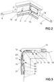
- FIG. 2 shows a left upper corner of the wing 2 of Figure 1 in a perspective view. It can be seen that the Eckumlenkung 11 an aperture 15 to cover the in FIG. 1 illustrated pocket 12 has.
- the window also has an opening 17 closed by a plug 16.
- FIG. 3 shows a sectional view through the wing 2 FIG. 2 along the line III - III.
- the corner drive 11 has two legs 18, 19 secured in the wing 2, in which a spring strip 20 is guided.
- the spring band 20 is connected via the clutches 13, 14 with the drive rod sections 8, 10.
- One of the clutches 13 is arranged completely inside the pocket 12 and accessible only via the opening 17 closed by the stopper 16.
- This coupling 13 has a coupling element 21, which is guided transversely to the directions of movement of an end piece 22 of the one drive rod section 8 and a connecting piece 23 of the spring band 20 of the corner drive 13.
- the coupling element 21 generates a positive connection between the end piece 22 of the drive rod section 8 and the connection piece 23 of the corner drive eleventh
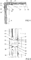
- FIG. 4 shows a further embodiment of the wing 2, which differs from the FIGS. 2 and 3 only differs in that a pocket 24 for receiving a corner 25 is perpendicular to the plane and thus perpendicular to the plane of the window accessible.
- the corner drive 25 has two identically constructed couplings 26, 27, each with a coupling element 28, 29. These couplings 26, 27 are like the coupling element 21 having a coupling 13 from FIG. 3 constructed and exclusively accessible via a closed by a stopper 30, 31 opening 32, 33 in the wing 2.
- FIG. 5 shows a greatly enlarged example of the coupling element 21 having the clutch 13 FIG. 3 , It can be seen that the spring band 20 is riveted to the connector 23 of the corner 13.
- the connecting piece 23 has a recess 34 with positive-locking surfaces 35.
- the end piece 22 of the driving rod section 8 also has positive-locking surfaces 36.
- the coupling element 21 connects the interlocking surfaces 35, 36 of the connecting piece 23 and the end piece 22 transversely to the direction of movement of the driving rod section 8 End piece 22 are arranged in an opening 37 in a row as internal teeth.
- the coupling element 21 has an internal toothing corresponding outer teeth 38, but is designed to be shorter than the series of form-fitting surfaces 36 in the end piece 22 of the drive rod section 8. In this way, a tolerance compensation between the drive rod section 8 and the Eckumlenkung 11 is generated.
- FIG. 6 shows a further embodiment of a concealed coupling 39 for connecting a corner drive 40 with one of in FIG. 1
- the corner drive 40 has a slider 41 with an arcuate guide 42 for a spring band 43.
- a fitting 44 for connection to the drive rod portion 8 is formed as an end portion of the spring band 43.
- a coupling element 45 is connected to the connecting piece 44 of the spring band 43 and the end piece 22 of the drive rod section 8. Positive locking surfaces 47 of the connecting piece 44 for connection to the coupling element 45 are thus arranged directly on the spring band 43.
- the slider 41 is guided longitudinally in a leg 48 of the corner drive 40 and accessible by a second leg 49.
- FIG. 7 shows the corner 40 from FIG. 6 before the connection with the one drive rod section 8 and with the slider 41 in the extended state.
- the coupling element 45 is arranged on a transversely to the one drive rod section 8 pivotable, formed by a portion of the spring band 43 arm 46. Due to the spring force of the spring band 43, the arm 46 is pivoted away from the drive rod section 8. Push the slider 41 in the in FIG. 6 shown position, the arm 46 is deflected and the coupling element 45 is pressed into the form-locking surfaces 36 of the end piece 22 of the drive rod section 8 and the power flow from the drive rod section 8 in the spring band 43 of the corner 40 made.
Landscapes
- Engineering & Computer Science (AREA)
- Mechanical Engineering (AREA)
- Lock And Its Accessories (AREA)
- Pivots And Pivotal Connections (AREA)
- Orthopedics, Nursing, And Contraception (AREA)
- Closing And Opening Devices For Wings, And Checks For Wings (AREA)
- Buckles (AREA)
Claims (9)
- Couplage pour la liaison d'un renvoi d'angle (11, 25, 40) comprenant une bande ressort (20) guidée par l'intermédiaire de deux branches (18, 19) à une section de bielle (8 à 10), mobile longitudinalement, d'une ferrure à bielle (3) avec des premières surfaces à complémentarité de forme (35) disposées au niveau d'une pièce d'extrémité (22) de la section de bielle (8 à 10) et avec des deuxièmes surfaces à complémentarité de forme (36) disposées au niveau d'une pièce de raccordement (23) du renvoi d'angle (11, 25, 40), la pièce de raccordement (23) étant guidée de manière mobile au niveau d'une des branches et les surfaces à complémentarité de forme (35) de la pièce d'extrémité (22) de la section de bielle (8 à 10) et de la pièce de raccordement (23) du renvoi d'angle (11, 25, 40) étant reliées entre elles, un élément de couplage (21, 28, 29, 45) étant disposé transversalement par rapport aux directions de mouvement de la pièce d'extrémité (22) de la section de bielle (8) et de la pièce de raccordement (23, 44) du renvoi d'angle (11, 25, 40) et étant relié, dans l'état monté, avec les deux surfaces à complémentarité de forme (35, 36, 47), caractérisé en ce que la pièce de raccordement (44) est fabriquée comme une section d'extrémité de la bande ressort (43) du renvoi d'angle (40) et est conçu, avec l'élément de couplage (45), comme une unité pré-montée.
- Couplage selon la revendication 1, caractérisé en ce que les surfaces à complémentarité de forme (35, 36, 47) sont disposées à l'intérieur d'au moins un percement (37) de la pièce d'extrémité (22) de la section de bielle (8) et/ou de la pièce de raccordement (23, 44) du renvoi d'angle (11, 25, 40).
- Couplage selon la revendication 1 ou 2, caractérisé en ce que plusieurs surfaces à complémentarité de forme (36) de la pièce de raccordement (23, 44) du renvoi d'angle (11, 25, 40) et/ou de la pièce d'extrémité (22) de la section de bielle (8) sont disposées sur une ligne et en ce que la ligne des surfaces à complémentarité de forme (36) est plus longue que l'élément de couplage (21).
- Couplage selon la revendication 3, caractérisé en ce que les surfaces à complémentarité de forme (36) disposées sur une ligne sont conçues comme une denture interne de l'au moins un percement (37), en ce que le percement (37) est de forme allongée et en ce que l'élément de couplage (21) présente une denture externe (38) correspondant à la denture interne du percement (37).
- Couplage selon l'une des revendications précédentes, caractérisé en ce que l'élément de couplage (21, 28, 29, 45) est relié de manière amovible avec la pièce d'extrémité (22) de la section de bielle (8) et la pièce de raccordement (23, 44) du renvoi d'angle (11, 25, 40).
- Couplage selon l'une des revendications précédentes, caractérisé en ce que l'élément de couplage (45) est disposé sur un bras (46), en ce que le bras (46) est logé de manière pivotante dans une branche (48) du renvoi d'angle (40) et en ce que le bras (46) est accessible à partir d'une autre branche (49) du renvoi d'angle (40).
- Couplage selon la revendication 6, caractérisé en ce que le renvoi d'angle (40) comprend un curseur (41) et en ce que le curseur (41) est guidé dans la branche (48) comprenant le bras (46) et soutient le bras (46), dans l'état inséré dans la branche (48).
- Couplage selon la revendication 6 ou 7, caractérisé en ce que la bande ressort (43) du renvoi d'angle (40) est conçue comme un bras (46).
- Couplage selon l'une des revendications précédentes, caractérisé en ce qu'une plaque (15) pour le recouvrement d'une poche (12) logeant le renvoi d'angle (11) est disposée dans la fenêtre exclusivement sur une des branches (19) du renvoi d'angle (11).
Priority Applications (1)
| Application Number | Priority Date | Filing Date | Title |
|---|---|---|---|
| PL09176904T PL2199505T3 (pl) | 2008-12-15 | 2009-11-24 | Połączenie do łączenia zawierającego taśmę sprężynową, prowadzoną przez dwa ramiona, obejścia narożnego na przesuwnym wzdłużnie odcinku zasuwnicy |
Applications Claiming Priority (1)
| Application Number | Priority Date | Filing Date | Title |
|---|---|---|---|
| DE102008054672A DE102008054672A1 (de) | 2008-12-15 | 2008-12-15 | Kupplung zur Anbindung einer ein über zwei Schenkel geführtes Federband aufweisenden Eckumlenkung an einem längsverschieblichen Treibstangenabschnitt |
Publications (3)
| Publication Number | Publication Date |
|---|---|
| EP2199505A2 EP2199505A2 (fr) | 2010-06-23 |
| EP2199505A3 EP2199505A3 (fr) | 2011-08-24 |
| EP2199505B1 true EP2199505B1 (fr) | 2018-02-21 |
Family
ID=41819243
Family Applications (1)
| Application Number | Title | Priority Date | Filing Date |
|---|---|---|---|
| EP09176904.2A Not-in-force EP2199505B1 (fr) | 2008-12-15 | 2009-11-24 | Couplage destiné à la connexion d'une bande à ressorte dirigée par des branches l'une sur l'autre comprenant un renvoi d'angle sur une section de bielles à déplacement longitudinal |
Country Status (3)
| Country | Link |
|---|---|
| EP (1) | EP2199505B1 (fr) |
| DE (1) | DE102008054672A1 (fr) |
| PL (1) | PL2199505T3 (fr) |
Families Citing this family (3)
| Publication number | Priority date | Publication date | Assignee | Title |
|---|---|---|---|---|
| DE102016004919A1 (de) * | 2016-04-23 | 2017-10-26 | Roto Frank Aktiengesellschaft | Beschlag für ein Fenster, eine Tür oder dergleichen |
| DE102017201250A1 (de) | 2017-01-26 | 2018-07-26 | Aug. Winkhaus Gmbh & Co. Kg | Eckumlenkung für einen Treibstangenbeschlag |
| CN112523631A (zh) * | 2020-12-17 | 2021-03-19 | 广东合和建筑五金制品有限公司 | 一种滑撑传动功能的多锁点平开窗系统 |
Family Cites Families (6)
| Publication number | Priority date | Publication date | Assignee | Title |
|---|---|---|---|---|
| DE3141244A1 (de) * | 1981-10-16 | 1983-06-01 | Geze Gmbh, 7250 Leonberg | Vorrichtung zur kupplung senkrecht zueinander verlaufender treibstangen |
| DE4240503A1 (de) | 1992-12-02 | 1994-06-09 | Klaus Knaust | Kunststoff- oder Aluminiumfenster mit einem Rahmen aus extrudierten oder gepreßten Hohlprofilen |
| DE9404964U1 (de) * | 1994-03-23 | 1994-05-19 | Roto Frank Ag, 70771 Leinfelden-Echterdingen | Beschlag für ein Fenster, eine Tür o.dgl. |
| DE19921212B4 (de) * | 1999-05-07 | 2013-05-16 | Roto Frank Ag | Stulpschienenbeschlag für ein Fenster, eine Tür o. dgl. |
| DE20201319U1 (de) * | 2002-01-29 | 2002-06-20 | Siegenia-Frank Kg, 57074 Siegen | Eckumlenkung |
| DE202008005830U1 (de) * | 2008-04-26 | 2008-07-03 | Roto Frank Ag | Eckumlenkung für ein Fenster, eine Tür o.dgl. |
-
2008
- 2008-12-15 DE DE102008054672A patent/DE102008054672A1/de not_active Withdrawn
-
2009
- 2009-11-24 PL PL09176904T patent/PL2199505T3/pl unknown
- 2009-11-24 EP EP09176904.2A patent/EP2199505B1/fr not_active Not-in-force
Non-Patent Citations (1)
| Title |
|---|
| None * |
Also Published As
| Publication number | Publication date |
|---|---|
| EP2199505A2 (fr) | 2010-06-23 |
| DE102008054672A1 (de) | 2010-06-17 |
| PL2199505T3 (pl) | 2018-06-29 |
| EP2199505A3 (fr) | 2011-08-24 |
Similar Documents
| Publication | Publication Date | Title |
|---|---|---|
| EP0711896A2 (fr) | Dispositif de fermeture pour fenêtres, portes ou similaires | |
| EP3791035B1 (fr) | Ensemble formant ferrure pour une fenêtre coulissante ou une porte coulissante | |
| DE102009057325A1 (de) | Schiebetüre für ein Fahrzeug | |
| EP2199505A2 (fr) | Couplage destiné à la connexion d'une bande à ressorte dirigée par des branches l'une sur l'autre comprenant un renvoi d'angle sur une section de bielles à déplacement longitudinal | |
| WO2017001226A1 (fr) | Joint d'abaissement | |
| EP2642054A2 (fr) | Penture pour un agencement couvert entre un cadre de porte et un vantail | |
| EP2770143A2 (fr) | Entraînement d'une crémone de fenêtre ou de porte | |
| DE19859546A1 (de) | Schieberstangenbefestigungs- und -führungselement | |
| EP2607583B1 (fr) | Elément de ferrure pour une espagnolette | |
| DE2317039C3 (de) | Scharniergelenk für Fenster, Türen o.dgl. | |
| EP3162994B1 (fr) | Mécanisme d'entraînement pour une ferrure à crémone | |
| DE102004060717B4 (de) | Verschluss zur Verriegelung eines Flügels in einem Rahmen eines Fensters | |
| EP3450662B1 (fr) | Dispositif d'entraînement d'une ferrure à tige d'entraînement et procédé de montage d'un tel dispositif d'entraînement | |
| DE102014117419A1 (de) | Beschlag für Fenster, Türen und dergleichen und Getriebeeinheit für einen solchen Beschlag | |
| EP2532816B1 (fr) | Dispositif d'entraînement pour une armature de bielle | |
| EP0916791B1 (fr) | Mécanisme de verrouillage avec un dispositif de guidage pour le guidage d'une tige de verrouillage coulissante qui est montée sur un élément de montage | |
| DE202007011079U1 (de) | Ausstellvorrichtung | |
| EP2233669A2 (fr) | Agencement d'armature et fenêtre ou porte dotée d'un tel agencement d'armature | |
| DE29818045U1 (de) | Beschlag für Klappfenster, insbesondere von Wohnwagen, Mobilheimen u.dgl. | |
| EP2317058B1 (fr) | Ferrure à crémone pour une fenêtre comprenant un vantail pivotant contre un cadre | |
| EP2543803B1 (fr) | Bielle pour une ferrure de bielle | |
| EP1867818B1 (fr) | Fermeture pour une ferrure de bielle et fenêtre, porte fenêtre ou analogue dotée d'une telle fermeture | |
| DE20012189U1 (de) | Eckumlenkung | |
| DE102005000189A1 (de) | Beschlagteil für einen Treibstangenbeschlag | |
| DE202009005886U1 (de) | Scharnierbeschlag für Fenster oder Türen |
Legal Events
| Date | Code | Title | Description |
|---|---|---|---|
| PUAI | Public reference made under article 153(3) epc to a published international application that has entered the european phase |
Free format text: ORIGINAL CODE: 0009012 |
|
| AK | Designated contracting states |
Kind code of ref document: A2 Designated state(s): AT BE BG CH CY CZ DE DK EE ES FI FR GB GR HR HU IE IS IT LI LT LU LV MC MK MT NL NO PL PT RO SE SI SK SM TR |
|
| AX | Request for extension of the european patent |
Extension state: AL BA RS |
|
| PUAL | Search report despatched |
Free format text: ORIGINAL CODE: 0009013 |
|
| AK | Designated contracting states |
Kind code of ref document: A3 Designated state(s): AT BE BG CH CY CZ DE DK EE ES FI FR GB GR HR HU IE IS IT LI LT LU LV MC MK MT NL NO PL PT RO SE SI SK SM TR |
|
| AX | Request for extension of the european patent |
Extension state: AL BA RS |
|
| RIC1 | Information provided on ipc code assigned before grant |
Ipc: E05C 9/00 20060101AFI20110718BHEP |
|
| 17P | Request for examination filed |
Effective date: 20111213 |
|
| REG | Reference to a national code |
Ref country code: DE Ref legal event code: R079 Ref document number: 502009014737 Country of ref document: DE Free format text: PREVIOUS MAIN CLASS: E05C0009000000 Ipc: E05C0009200000 |
|
| GRAJ | Information related to disapproval of communication of intention to grant by the applicant or resumption of examination proceedings by the epo deleted |
Free format text: ORIGINAL CODE: EPIDOSDIGR1 |
|
| GRAP | Despatch of communication of intention to grant a patent |
Free format text: ORIGINAL CODE: EPIDOSNIGR1 |
|
| RIC1 | Information provided on ipc code assigned before grant |
Ipc: E05C 9/06 20060101ALI20170710BHEP Ipc: E05B 53/00 20060101ALI20170710BHEP Ipc: E05F 7/08 20060101ALI20170710BHEP Ipc: E05C 9/20 20060101AFI20170710BHEP Ipc: E05C 9/24 20060101ALI20170710BHEP |
|
| GRAP | Despatch of communication of intention to grant a patent |
Free format text: ORIGINAL CODE: EPIDOSNIGR1 |
|
| INTG | Intention to grant announced |
Effective date: 20170929 |
|
| GRAS | Grant fee paid |
Free format text: ORIGINAL CODE: EPIDOSNIGR3 |
|
| GRAA | (expected) grant |
Free format text: ORIGINAL CODE: 0009210 |
|
| AK | Designated contracting states |
Kind code of ref document: B1 Designated state(s): AT BE BG CH CY CZ DE DK EE ES FI FR GB GR HR HU IE IS IT LI LT LU LV MC MK MT NL NO PL PT RO SE SI SK SM TR |
|
| REG | Reference to a national code |
Ref country code: GB Ref legal event code: FG4D Free format text: NOT ENGLISH |
|
| REG | Reference to a national code |
Ref country code: CH Ref legal event code: EP |
|
| REG | Reference to a national code |
Ref country code: AT Ref legal event code: REF Ref document number: 971896 Country of ref document: AT Kind code of ref document: T Effective date: 20180315 |
|
| REG | Reference to a national code |
Ref country code: IE Ref legal event code: FG4D Free format text: LANGUAGE OF EP DOCUMENT: GERMAN |
|
| REG | Reference to a national code |
Ref country code: DE Ref legal event code: R096 Ref document number: 502009014737 Country of ref document: DE |
|
| REG | Reference to a national code |
Ref country code: NL Ref legal event code: MP Effective date: 20180221 |
|
| REG | Reference to a national code |
Ref country code: LT Ref legal event code: MG4D |
|
| PG25 | Lapsed in a contracting state [announced via postgrant information from national office to epo] |
Ref country code: ES Free format text: LAPSE BECAUSE OF FAILURE TO SUBMIT A TRANSLATION OF THE DESCRIPTION OR TO PAY THE FEE WITHIN THE PRESCRIBED TIME-LIMIT Effective date: 20180221 Ref country code: HR Free format text: LAPSE BECAUSE OF FAILURE TO SUBMIT A TRANSLATION OF THE DESCRIPTION OR TO PAY THE FEE WITHIN THE PRESCRIBED TIME-LIMIT Effective date: 20180221 Ref country code: NO Free format text: LAPSE BECAUSE OF FAILURE TO SUBMIT A TRANSLATION OF THE DESCRIPTION OR TO PAY THE FEE WITHIN THE PRESCRIBED TIME-LIMIT Effective date: 20180521 Ref country code: FI Free format text: LAPSE BECAUSE OF FAILURE TO SUBMIT A TRANSLATION OF THE DESCRIPTION OR TO PAY THE FEE WITHIN THE PRESCRIBED TIME-LIMIT Effective date: 20180221 Ref country code: LT Free format text: LAPSE BECAUSE OF FAILURE TO SUBMIT A TRANSLATION OF THE DESCRIPTION OR TO PAY THE FEE WITHIN THE PRESCRIBED TIME-LIMIT Effective date: 20180221 Ref country code: NL Free format text: LAPSE BECAUSE OF FAILURE TO SUBMIT A TRANSLATION OF THE DESCRIPTION OR TO PAY THE FEE WITHIN THE PRESCRIBED TIME-LIMIT Effective date: 20180221 Ref country code: CY Free format text: LAPSE BECAUSE OF FAILURE TO SUBMIT A TRANSLATION OF THE DESCRIPTION OR TO PAY THE FEE WITHIN THE PRESCRIBED TIME-LIMIT Effective date: 20180221 |
|
| PG25 | Lapsed in a contracting state [announced via postgrant information from national office to epo] |
Ref country code: GR Free format text: LAPSE BECAUSE OF FAILURE TO SUBMIT A TRANSLATION OF THE DESCRIPTION OR TO PAY THE FEE WITHIN THE PRESCRIBED TIME-LIMIT Effective date: 20180522 Ref country code: SE Free format text: LAPSE BECAUSE OF FAILURE TO SUBMIT A TRANSLATION OF THE DESCRIPTION OR TO PAY THE FEE WITHIN THE PRESCRIBED TIME-LIMIT Effective date: 20180221 Ref country code: LV Free format text: LAPSE BECAUSE OF FAILURE TO SUBMIT A TRANSLATION OF THE DESCRIPTION OR TO PAY THE FEE WITHIN THE PRESCRIBED TIME-LIMIT Effective date: 20180221 Ref country code: BG Free format text: LAPSE BECAUSE OF FAILURE TO SUBMIT A TRANSLATION OF THE DESCRIPTION OR TO PAY THE FEE WITHIN THE PRESCRIBED TIME-LIMIT Effective date: 20180521 |
|
| PG25 | Lapsed in a contracting state [announced via postgrant information from national office to epo] |
Ref country code: MT Free format text: LAPSE BECAUSE OF FAILURE TO SUBMIT A TRANSLATION OF THE DESCRIPTION OR TO PAY THE FEE WITHIN THE PRESCRIBED TIME-LIMIT Effective date: 20180221 |
|
| PG25 | Lapsed in a contracting state [announced via postgrant information from national office to epo] |
Ref country code: RO Free format text: LAPSE BECAUSE OF FAILURE TO SUBMIT A TRANSLATION OF THE DESCRIPTION OR TO PAY THE FEE WITHIN THE PRESCRIBED TIME-LIMIT Effective date: 20180221 Ref country code: EE Free format text: LAPSE BECAUSE OF FAILURE TO SUBMIT A TRANSLATION OF THE DESCRIPTION OR TO PAY THE FEE WITHIN THE PRESCRIBED TIME-LIMIT Effective date: 20180221 |
|
| REG | Reference to a national code |
Ref country code: DE Ref legal event code: R097 Ref document number: 502009014737 Country of ref document: DE |
|
| PG25 | Lapsed in a contracting state [announced via postgrant information from national office to epo] |
Ref country code: DK Free format text: LAPSE BECAUSE OF FAILURE TO SUBMIT A TRANSLATION OF THE DESCRIPTION OR TO PAY THE FEE WITHIN THE PRESCRIBED TIME-LIMIT Effective date: 20180221 Ref country code: CZ Free format text: LAPSE BECAUSE OF FAILURE TO SUBMIT A TRANSLATION OF THE DESCRIPTION OR TO PAY THE FEE WITHIN THE PRESCRIBED TIME-LIMIT Effective date: 20180221 Ref country code: SK Free format text: LAPSE BECAUSE OF FAILURE TO SUBMIT A TRANSLATION OF THE DESCRIPTION OR TO PAY THE FEE WITHIN THE PRESCRIBED TIME-LIMIT Effective date: 20180221 Ref country code: SM Free format text: LAPSE BECAUSE OF FAILURE TO SUBMIT A TRANSLATION OF THE DESCRIPTION OR TO PAY THE FEE WITHIN THE PRESCRIBED TIME-LIMIT Effective date: 20180221 |
|
| PLBE | No opposition filed within time limit |
Free format text: ORIGINAL CODE: 0009261 |
|
| STAA | Information on the status of an ep patent application or granted ep patent |
Free format text: STATUS: NO OPPOSITION FILED WITHIN TIME LIMIT |
|
| 26N | No opposition filed |
Effective date: 20181122 |
|
| PGFP | Annual fee paid to national office [announced via postgrant information from national office to epo] |
Ref country code: HU Payment date: 20181123 Year of fee payment: 11 |
|
| PG25 | Lapsed in a contracting state [announced via postgrant information from national office to epo] |
Ref country code: SI Free format text: LAPSE BECAUSE OF FAILURE TO SUBMIT A TRANSLATION OF THE DESCRIPTION OR TO PAY THE FEE WITHIN THE PRESCRIBED TIME-LIMIT Effective date: 20180221 |
|
| PGFP | Annual fee paid to national office [announced via postgrant information from national office to epo] |
Ref country code: IT Payment date: 20181122 Year of fee payment: 10 Ref country code: FR Payment date: 20181127 Year of fee payment: 10 Ref country code: GB Payment date: 20181130 Year of fee payment: 10 |
|
| REG | Reference to a national code |
Ref country code: CH Ref legal event code: PL |
|
| PG25 | Lapsed in a contracting state [announced via postgrant information from national office to epo] |
Ref country code: MC Free format text: LAPSE BECAUSE OF FAILURE TO SUBMIT A TRANSLATION OF THE DESCRIPTION OR TO PAY THE FEE WITHIN THE PRESCRIBED TIME-LIMIT Effective date: 20180221 Ref country code: LU Free format text: LAPSE BECAUSE OF NON-PAYMENT OF DUE FEES Effective date: 20181124 |
|
| REG | Reference to a national code |
Ref country code: BE Ref legal event code: MM Effective date: 20181130 |
|
| REG | Reference to a national code |
Ref country code: IE Ref legal event code: MM4A |
|
| PG25 | Lapsed in a contracting state [announced via postgrant information from national office to epo] |
Ref country code: LI Free format text: LAPSE BECAUSE OF NON-PAYMENT OF DUE FEES Effective date: 20181130 Ref country code: CH Free format text: LAPSE BECAUSE OF NON-PAYMENT OF DUE FEES Effective date: 20181130 |
|
| PG25 | Lapsed in a contracting state [announced via postgrant information from national office to epo] |
Ref country code: IE Free format text: LAPSE BECAUSE OF NON-PAYMENT OF DUE FEES Effective date: 20181124 |
|
| PG25 | Lapsed in a contracting state [announced via postgrant information from national office to epo] |
Ref country code: BE Free format text: LAPSE BECAUSE OF NON-PAYMENT OF DUE FEES Effective date: 20181130 |
|
| PG25 | Lapsed in a contracting state [announced via postgrant information from national office to epo] |
Ref country code: TR Free format text: LAPSE BECAUSE OF FAILURE TO SUBMIT A TRANSLATION OF THE DESCRIPTION OR TO PAY THE FEE WITHIN THE PRESCRIBED TIME-LIMIT Effective date: 20180221 |
|
| PG25 | Lapsed in a contracting state [announced via postgrant information from national office to epo] |
Ref country code: PT Free format text: LAPSE BECAUSE OF FAILURE TO SUBMIT A TRANSLATION OF THE DESCRIPTION OR TO PAY THE FEE WITHIN THE PRESCRIBED TIME-LIMIT Effective date: 20180221 |
|
| PG25 | Lapsed in a contracting state [announced via postgrant information from national office to epo] |
Ref country code: MK Free format text: LAPSE BECAUSE OF NON-PAYMENT OF DUE FEES Effective date: 20180221 Ref country code: HU Free format text: LAPSE BECAUSE OF FAILURE TO SUBMIT A TRANSLATION OF THE DESCRIPTION OR TO PAY THE FEE WITHIN THE PRESCRIBED TIME-LIMIT; INVALID AB INITIO Effective date: 20091124 |
|
| PG25 | Lapsed in a contracting state [announced via postgrant information from national office to epo] |
Ref country code: IS Free format text: LAPSE BECAUSE OF FAILURE TO SUBMIT A TRANSLATION OF THE DESCRIPTION OR TO PAY THE FEE WITHIN THE PRESCRIBED TIME-LIMIT Effective date: 20180621 |
|
| GBPC | Gb: european patent ceased through non-payment of renewal fee |
Effective date: 20191124 |
|
| PG25 | Lapsed in a contracting state [announced via postgrant information from national office to epo] |
Ref country code: FR Free format text: LAPSE BECAUSE OF NON-PAYMENT OF DUE FEES Effective date: 20191130 Ref country code: IT Free format text: LAPSE BECAUSE OF NON-PAYMENT OF DUE FEES Effective date: 20191124 Ref country code: GB Free format text: LAPSE BECAUSE OF NON-PAYMENT OF DUE FEES Effective date: 20191124 |
|
| PGFP | Annual fee paid to national office [announced via postgrant information from national office to epo] |
Ref country code: AT Payment date: 20201118 Year of fee payment: 12 |
|
| PG25 | Lapsed in a contracting state [announced via postgrant information from national office to epo] |
Ref country code: PL Free format text: LAPSE BECAUSE OF NON-PAYMENT OF DUE FEES Effective date: 20191124 |
|
| PGFP | Annual fee paid to national office [announced via postgrant information from national office to epo] |
Ref country code: DE Payment date: 20211122 Year of fee payment: 13 |
|
| REG | Reference to a national code |
Ref country code: AT Ref legal event code: MM01 Ref document number: 971896 Country of ref document: AT Kind code of ref document: T Effective date: 20211124 |
|
| PG25 | Lapsed in a contracting state [announced via postgrant information from national office to epo] |
Ref country code: AT Free format text: LAPSE BECAUSE OF NON-PAYMENT OF DUE FEES Effective date: 20211124 |
|
| REG | Reference to a national code |
Ref country code: DE Ref legal event code: R119 Ref document number: 502009014737 Country of ref document: DE |
|
| P01 | Opt-out of the competence of the unified patent court (upc) registered |
Effective date: 20230515 |
|
| PG25 | Lapsed in a contracting state [announced via postgrant information from national office to epo] |
Ref country code: DE Free format text: LAPSE BECAUSE OF NON-PAYMENT OF DUE FEES Effective date: 20230601 |