EP2199518A1 - Profilé composite à isolation thermique et son procédé de fabrication - Google Patents
Profilé composite à isolation thermique et son procédé de fabrication Download PDFInfo
- Publication number
- EP2199518A1 EP2199518A1 EP08171342A EP08171342A EP2199518A1 EP 2199518 A1 EP2199518 A1 EP 2199518A1 EP 08171342 A EP08171342 A EP 08171342A EP 08171342 A EP08171342 A EP 08171342A EP 2199518 A1 EP2199518 A1 EP 2199518A1
- Authority
- EP
- European Patent Office
- Prior art keywords
- insulating body
- profile
- longitudinal direction
- profile parts
- composite profile
- Prior art date
- Legal status (The legal status is an assumption and is not a legal conclusion. Google has not performed a legal analysis and makes no representation as to the accuracy of the status listed.)
- Withdrawn
Links
- 239000002131 composite material Substances 0.000 title claims abstract description 64
- 238000004519 manufacturing process Methods 0.000 title claims abstract description 13
- 238000000034 method Methods 0.000 title claims abstract description 10
- 238000005192 partition Methods 0.000 claims abstract description 32
- 229910052751 metal Inorganic materials 0.000 claims abstract description 25
- 239000002184 metal Substances 0.000 claims abstract description 25
- 229910052782 aluminium Inorganic materials 0.000 claims abstract description 24
- XAGFODPZIPBFFR-UHFFFAOYSA-N aluminium Chemical compound [Al] XAGFODPZIPBFFR-UHFFFAOYSA-N 0.000 claims abstract description 24
- 239000000853 adhesive Substances 0.000 claims description 15
- 230000001070 adhesive effect Effects 0.000 claims description 15
- 238000000576 coating method Methods 0.000 claims description 9
- 239000000463 material Substances 0.000 claims description 9
- 239000011248 coating agent Substances 0.000 claims description 8
- 238000005476 soldering Methods 0.000 claims description 8
- 238000009413 insulation Methods 0.000 description 12
- 238000000926 separation method Methods 0.000 description 11
- 239000012212 insulator Substances 0.000 description 7
- 239000000243 solution Substances 0.000 description 6
- 229910000679 solder Inorganic materials 0.000 description 4
- 239000004033 plastic Substances 0.000 description 3
- 239000012720 thermal barrier coating Substances 0.000 description 3
- 230000003068 static effect Effects 0.000 description 2
- 230000009286 beneficial effect Effects 0.000 description 1
- 230000015572 biosynthetic process Effects 0.000 description 1
- 239000004020 conductor Substances 0.000 description 1
- 238000001816 cooling Methods 0.000 description 1
- 239000011521 glass Substances 0.000 description 1
- 238000000465 moulding Methods 0.000 description 1
- RVTZCBVAJQQJTK-UHFFFAOYSA-N oxygen(2-);zirconium(4+) Chemical compound [O-2].[O-2].[Zr+4] RVTZCBVAJQQJTK-UHFFFAOYSA-N 0.000 description 1
- 239000002984 plastic foam Substances 0.000 description 1
- RUDFQVOCFDJEEF-UHFFFAOYSA-N yttrium(III) oxide Inorganic materials [O-2].[O-2].[O-2].[Y+3].[Y+3] RUDFQVOCFDJEEF-UHFFFAOYSA-N 0.000 description 1
- 229910001928 zirconium oxide Inorganic materials 0.000 description 1
Images



Classifications
-
- E—FIXED CONSTRUCTIONS
- E06—DOORS, WINDOWS, SHUTTERS, OR ROLLER BLINDS IN GENERAL; LADDERS
- E06B—FIXED OR MOVABLE CLOSURES FOR OPENINGS IN BUILDINGS, VEHICLES, FENCES OR LIKE ENCLOSURES IN GENERAL, e.g. DOORS, WINDOWS, BLINDS, GATES
- E06B3/00—Window sashes, door leaves, or like elements for closing wall or like openings; Layout of fixed or moving closures, e.g. windows in wall or like openings; Features of rigidly-mounted outer frames relating to the mounting of wing frames
- E06B3/04—Wing frames not characterised by the manner of movement
- E06B3/263—Frames with special provision for insulation
- E06B3/2632—Frames with special provision for insulation with arrangements reducing the heat transmission, other than an interruption in a metal section
-
- E—FIXED CONSTRUCTIONS
- E06—DOORS, WINDOWS, SHUTTERS, OR ROLLER BLINDS IN GENERAL; LADDERS
- E06B—FIXED OR MOVABLE CLOSURES FOR OPENINGS IN BUILDINGS, VEHICLES, FENCES OR LIKE ENCLOSURES IN GENERAL, e.g. DOORS, WINDOWS, BLINDS, GATES
- E06B3/00—Window sashes, door leaves, or like elements for closing wall or like openings; Layout of fixed or moving closures, e.g. windows in wall or like openings; Features of rigidly-mounted outer frames relating to the mounting of wing frames
- E06B3/04—Wing frames not characterised by the manner of movement
- E06B3/263—Frames with special provision for insulation
- E06B3/2632—Frames with special provision for insulation with arrangements reducing the heat transmission, other than an interruption in a metal section
- E06B2003/26325—Frames with special provision for insulation with arrangements reducing the heat transmission, other than an interruption in a metal section the convection or radiation in a hollow space being reduced, e.g. by subdividing the hollow space
-
- E—FIXED CONSTRUCTIONS
- E06—DOORS, WINDOWS, SHUTTERS, OR ROLLER BLINDS IN GENERAL; LADDERS
- E06B—FIXED OR MOVABLE CLOSURES FOR OPENINGS IN BUILDINGS, VEHICLES, FENCES OR LIKE ENCLOSURES IN GENERAL, e.g. DOORS, WINDOWS, BLINDS, GATES
- E06B3/00—Window sashes, door leaves, or like elements for closing wall or like openings; Layout of fixed or moving closures, e.g. windows in wall or like openings; Features of rigidly-mounted outer frames relating to the mounting of wing frames
- E06B3/04—Wing frames not characterised by the manner of movement
- E06B3/263—Frames with special provision for insulation
- E06B2003/26349—Details of insulating strips
- E06B2003/2635—Specific form characteristics
- E06B2003/26352—Specific form characteristics hollow
- E06B2003/26356—Honeycomb
-
- E—FIXED CONSTRUCTIONS
- E06—DOORS, WINDOWS, SHUTTERS, OR ROLLER BLINDS IN GENERAL; LADDERS
- E06B—FIXED OR MOVABLE CLOSURES FOR OPENINGS IN BUILDINGS, VEHICLES, FENCES OR LIKE ENCLOSURES IN GENERAL, e.g. DOORS, WINDOWS, BLINDS, GATES
- E06B3/00—Window sashes, door leaves, or like elements for closing wall or like openings; Layout of fixed or moving closures, e.g. windows in wall or like openings; Features of rigidly-mounted outer frames relating to the mounting of wing frames
- E06B3/04—Wing frames not characterised by the manner of movement
- E06B3/263—Frames with special provision for insulation
- E06B2003/26349—Details of insulating strips
- E06B2003/2635—Specific form characteristics
- E06B2003/26358—Specific form characteristics stepped or undulated
-
- E—FIXED CONSTRUCTIONS
- E06—DOORS, WINDOWS, SHUTTERS, OR ROLLER BLINDS IN GENERAL; LADDERS
- E06B—FIXED OR MOVABLE CLOSURES FOR OPENINGS IN BUILDINGS, VEHICLES, FENCES OR LIKE ENCLOSURES IN GENERAL, e.g. DOORS, WINDOWS, BLINDS, GATES
- E06B3/00—Window sashes, door leaves, or like elements for closing wall or like openings; Layout of fixed or moving closures, e.g. windows in wall or like openings; Features of rigidly-mounted outer frames relating to the mounting of wing frames
- E06B3/04—Wing frames not characterised by the manner of movement
- E06B3/263—Frames with special provision for insulation
- E06B2003/26349—Details of insulating strips
- E06B2003/2635—Specific form characteristics
- E06B2003/26365—Composed of several similar parts positioned one after the other
-
- E—FIXED CONSTRUCTIONS
- E06—DOORS, WINDOWS, SHUTTERS, OR ROLLER BLINDS IN GENERAL; LADDERS
- E06B—FIXED OR MOVABLE CLOSURES FOR OPENINGS IN BUILDINGS, VEHICLES, FENCES OR LIKE ENCLOSURES IN GENERAL, e.g. DOORS, WINDOWS, BLINDS, GATES
- E06B3/00—Window sashes, door leaves, or like elements for closing wall or like openings; Layout of fixed or moving closures, e.g. windows in wall or like openings; Features of rigidly-mounted outer frames relating to the mounting of wing frames
- E06B3/04—Wing frames not characterised by the manner of movement
- E06B3/263—Frames with special provision for insulation
- E06B2003/26349—Details of insulating strips
- E06B2003/26369—Specific material characteristics
- E06B2003/26372—Specific material characteristics with coatings
-
- E—FIXED CONSTRUCTIONS
- E06—DOORS, WINDOWS, SHUTTERS, OR ROLLER BLINDS IN GENERAL; LADDERS
- E06B—FIXED OR MOVABLE CLOSURES FOR OPENINGS IN BUILDINGS, VEHICLES, FENCES OR LIKE ENCLOSURES IN GENERAL, e.g. DOORS, WINDOWS, BLINDS, GATES
- E06B3/00—Window sashes, door leaves, or like elements for closing wall or like openings; Layout of fixed or moving closures, e.g. windows in wall or like openings; Features of rigidly-mounted outer frames relating to the mounting of wing frames
- E06B3/04—Wing frames not characterised by the manner of movement
- E06B3/263—Frames with special provision for insulation
- E06B2003/26349—Details of insulating strips
- E06B2003/26369—Specific material characteristics
- E06B2003/26374—Specific material characteristics with parts of differing nature
-
- E—FIXED CONSTRUCTIONS
- E06—DOORS, WINDOWS, SHUTTERS, OR ROLLER BLINDS IN GENERAL; LADDERS
- E06B—FIXED OR MOVABLE CLOSURES FOR OPENINGS IN BUILDINGS, VEHICLES, FENCES OR LIKE ENCLOSURES IN GENERAL, e.g. DOORS, WINDOWS, BLINDS, GATES
- E06B3/00—Window sashes, door leaves, or like elements for closing wall or like openings; Layout of fixed or moving closures, e.g. windows in wall or like openings; Features of rigidly-mounted outer frames relating to the mounting of wing frames
- E06B3/04—Wing frames not characterised by the manner of movement
- E06B3/263—Frames with special provision for insulation
- E06B2003/26349—Details of insulating strips
- E06B2003/26369—Specific material characteristics
- E06B2003/26376—Non-plastic materials, e.g. wood, metal
Definitions
- the present invention relates to a thermally insulated composite profile for windows, doors, facades or the like consisting of at least two spaced-apart profile parts made of light metal, in particular aluminum, which are interconnected via at least one insulating body.
- the invention further relates to a method for producing such a thermally insulated composite profile.
- Such a thermally insulated composite profile is, for example, in Fig. 1 shown. Accordingly, this is a composite profile 1 consisting of a first, to be arranged on the outside of the building profile part 2, also called “outer shell”, and a second, to be arranged on the building side profile part 4, also called “inner shell”. Both profile parts 2, 4 are usually made of a light metal, such as aluminum. Since aluminum is a very good conductor of heat, the two profile parts 2, 4 are arranged spaced from each other and connected to each other by means of two insulating webs 3 made of plastic.
- the Kunststoffisolierstege 3 are frictionally and / or positively fixed at their longitudinal edges in undercut grooves 6 of the profile parts 2, 4 by molding a metal web and prevent direct heat conduction or cooling line from the building outside to the building inside by the aluminum profile parts 2, 4th
- insulating strips 3 In order to ensure such a “shear-resistant composite", coming in the composite profile 1 insulating strips 3 must meet high mechanical requirements. Specifically, it is inevitable to increase the stability causing thickness (thickness) of the material used for the insulating strips 3 accordingly. However, this counteracts the thermal separation, since the heat insulation between the outer and inner shell 2, 4, the lower, the more material is used for the Isolierstege 3.
- the insulating webs 3 are formed so that they are substantially perpendicular to the profile parts 2, 4 and thus connect the profile parts 2, 4 on the shortest path together.
- this also increases the mechanical stability of the effected with the insulating 3 connection between the profile parts 2, 4, however, this measure also has a negative impact on the overall achievable thermal insulation, since the heat flow of the direct connection between the outer and inner shell 2, 4th follows.
- the present invention has the object, a composite profile of the type mentioned in such a way that in a simple to implement, but effective way, the thermal insulation between the two profile parts of the composite profile can be improved. Furthermore, a method for producing such a composite profile is to be specified.
- thermoly insulated composite profile of the type mentioned in the present invention that the insulating body of a plurality of partitions made of light metal, in particular aluminum, is constructed, which are locally connected to each other, that a plurality of air chambers is formed.
- the insulating body which has a plurality of air chambers according to the invention, forms between the profile parts of the composite profile a thermal separation plane which limits the heat flow from one profile part to the other profile part to a minimum.
- the air chambers of the insulating body serve the thermal insulation, while the intermediate walls of the insulating body, which are made of light metal, in particular aluminum, ensure the required mechanical connection between the profile parts.
- the insulating body is formed as a honeycomb body arrangement, wherein each honeycomb of the insulating body constitutes an air chamber.
- This honeycomb body assembly is formed by stacking intermediate walls of light metal, in particular aluminum, wherein the stacked intermediate walls are mutually connected to each other locally, so that a monolithic honeycomb body is formed.
- the honeycomb structure of the insulator results in a high mechanical strength at relatively low weight or low material, which on the one hand with regard to the required shear-resistant bond between the two profile parts of the composite profile and on the other hand with regard to the thermal insulation between the profile parts of the composite profile is beneficial.
- the knowledge is exploited that the cells of the honeycomb body arrangement guarantee a high mechanical strength, while at the same time the cells of the honeycomb body arrangement form air chambers for providing a thermal separation between the two profile parts to be joined.
- the insulating body is formed by stacking sheet metal layers (intermediate walls of light metal, in particular aluminum), it being conceivable in principle that these sheet metal layers are at least partially structured, so that the insulating body has a plurality of air chambers.
- the structuring of the intermediate walls made of light metal (aluminum) is preferably formed only after the local joining of the stacked intermediate walls.
- first each intermediate wall of the plurality of intermediate walls is connected to at least one intermediate wall adjacent thereto via a plurality of mutually separated connection regions, in particular adhesive or soldering points, wherein the stacking direction of the intermediate walls coincides with the spacing direction of the two profile parts.
- the insulating body can be pulled apart in the stacking direction, so that the respective intermediate walls, a structure is imposed, as a result, a honeycomb body assembly is formed with a plurality of air chambers.
- the intermediate walls are at least partially coated with a suitable heat-insulating coating, this heat-insulating coating having a lower thermal conductivity compared to the material of the intermediate walls (aluminum).
- a thermal barrier coating for example, coatings of zirconium oxide (ZrO 2 ), the lattice structure by the addition of yttria (Y 2 O 3 ) is stabilized or at least partially stabilized, in question.
- ZrO 2 zirconium oxide
- Y 2 O 3 yttria
- each of the plurality of partitions with at least one intermediate wall adjacent thereto via a plurality of mutually separated connection regions, in particular soldering or adhesive regions.
- each of the plurality of partitions at least one adjacent thereto intermediate wall via a plurality of extending in the longitudinal direction of the air chambers adhesive strips.
- a honeycomb body structure for the insulating body can be formed by stacking the plurality of intermediate walls, it is preferred, on the one hand that in the stacking direction formed on a first intermediate wall in the longitudinal direction of the insulating connecting areas (in particular adhesive or solder strips) to the connecting areas offset, which are formed in the longitudinal direction of the insulating body on a second intermediate wall which is adjacent to the first intermediate wall, and on the other hand that viewed in the stacking direction, the connecting portions formed on the first intermediate wall in the longitudinal direction of the insulating body are aligned with the connecting portions, in the longitudinal direction of the insulating body are formed on a third intermediate wall, which is adjacent to the second intermediate wall.
- the connecting portions formed on the first intermediate wall in the longitudinal direction of the insulating body are aligned with the connecting portions, in the longitudinal direction of the insulating body are formed on a third intermediate wall, which is adjacent to the second intermediate wall.
- connection areas adheresive / soldering strips or adhesive / soldering points
- This approach has the further advantage that in a particularly easy to implement manner with one and the same insulating the distance between the two interconnected with the insulating body profile parts can be set to any desired values. It is therefore no longer necessary to provide for differently spaced profile parts insulating body with different dimensions.
- the insulating body is arranged between the two profile parts of the composite profile such that the air chambers of the insulating body extend perpendicular to the longitudinal direction of the at least two profile parts.
- the insulating body is arranged between the profile parts such that the air chambers extend parallel to the longitudinal direction of the two profile parts, so as not to ensure heat transfer due to air circulation in the air chambers.
- At least one of the two profile parts of the composite profile is directly connected to an intermediate wall, which together with a plurality of other intermediate walls builds up the insulating body.
- the connection between the intermediate wall and the profile part can be formed for example by an adhesive or solder joint. Due to the fact that the intermediate wall of the insulating body lying in the stacking direction is connected directly to one of the two profile parts of the composite profile, it is possible to dispense with the formation of metal webs etc. on the profile parts. In particular, it is no longer necessary to provide, for example, suitable grooves into which parts of the insulating body must be received in a force-locking and / or form-locking manner.
- the invention is not only directed to a thermally insulated composite profile in which the thermal parting plane between the two profile parts is formed by means of an insulating body having a honeycomb structure with a plurality of air chambers to control the heat flow from one profile part of the composite profile to the other profile part of the Limit composite profiles. Rather, the present invention is also characterized by a method for producing such a thermally insulated composite profile, wherein the two profile parts made of light metal, in particular aluminum, spaced from each other and connected to each other via an extending in the longitudinal direction of the profile parts insulating body.
- the invention provides that the insulating body is formed by a plurality of partitions made of light metal, in particular aluminum, which are stacked and connected to each other with a plurality of extending in the longitudinal direction of the insulating connecting portions, wherein the stacking direction of the intermediate walls coincides with the spacing direction the two profile parts, and wherein after connecting the insulating body with the two profile parts, these are pulled apart by a freely definable distance in the stacking direction relative to each other.
- a conventional thermally insulated composite profile 1 is shown, which consists of a first, to be arranged on a building exterior profile part 2 and a second, to be arranged on a building side profile part 4. Both profile parts 2, 4 are connected to each other by means of two insulating webs 3 made of plastic.
- the Kunststoffisolierstege 3 are used for mechanical connection and thermal separation of the two profile parts 2, 4 of the composite profile 1. For this reason, in the in Fig. 1 illustrated composite profile 1 for use coming insulating bars 3 in cross-section made relatively thick, since the insulating bars 3 must ensure a rigid connection between the two profile parts 2, 4.
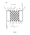
- FIG. 2 an embodiment of the inventive thermally insulated composite profile 100 is shown in a cross-sectional view.
- the composite profile 100 according to Fig. 2 consists of two spaced-apart profile parts 2, 4 of light metal, in particular aluminum, which are interconnected via an insulating body 10.
- the insulating body 10 has a honeycomb structure and forms between the profile parts 2, 4, a thermal separation plane, the heat flow from the one profile part 2; 4 to the other profile part 4; 2 of the composite profile 100 is limited to a minimum.
- the insulating body 10 used for the thermal insulation of the two profile parts 2, 4 of the composite profile 100 is constructed from a plurality of intermediate walls 11 made of light metal, in particular aluminum. These intermediate walls 11 are connected to each other locally via a plurality of connecting regions 14, that between the adjacent intermediate walls 11-1, ..., 11-8 on the one hand and the intermediate walls 11-1, 11-8, which directly adjacent to an inner side 2a, 4a of a profile part 2, 4, a plurality of air chambers 12th is formed.
- the air chambers 12 extend substantially parallel to the longitudinal direction of the profile parts 2, 4 or parallel to the longitudinal direction of the insulating 10.
- the insulating body 10 rotated by 90 ° between the two profile parts 2, 4 to arrange such in that the air chambers 12 formed between the adjacent intermediate walls arranged air chambers 12 extend perpendicular to the longitudinal direction of the two profile parts.
- Fig. 4a to 4d consists in the illustrated preferred embodiment of the composite profile 100 of the insulating body 10 of a plurality of intermediate walls 11, which are coated with a heat-insulating coating 13.
- the intermediate walls 11 coated with the heat-insulating coating 13 are connected to one another via a multiplicity of mutually separated connection regions 14, in particular adhesive or soldering regions.
- connection areas 14-1 formed in the longitudinal direction of the insulator seen in the stacking direction S are offset from the connection areas 14-2 formed in the longitudinal direction of the insulator 10 on a second partition wall 11-2. which is adjacent to the first partition 11-1.
- the connecting portions 14-1 formed on the first partition 11-1 in the longitudinal direction of the insulating body 10 align with the connection portions 14-3 formed in the longitudinal direction of the insulating body 10 on a third partition 11-3 which are different from the first partition 11-1 and adjacent to the second partition 11-2.
- the insulator 10 has a honeycomb structure, each honeycomb including an air chamber 12.
- the honeycomb structure of the insulating body 10 results in a high mechanical strength at relatively low weight and comparatively low material. This makes the use of the honeycomb structure as an insulating body 10 in the thermally insulated composite profile 100 attractive.
- the required mechanical strength of the insulating body 10 and thus of the entire composite profile 100 is ensured. This mechanical strength is increased again, if - as already indicated - the insulating body 10 is rotated by 90 ° between the profile parts 2, 4 is used, in which case the air chambers 12 are perpendicular to the longitudinal direction of the profile parts 2, 4.
- FIGS. 3a to 3c the manufacturing method for an embodiment of the composite profile 100 according to the invention described.
- Fig. 3a for the production of a thermally insulated composite profile 100, two profile parts 2, 4 made of light metal, such as aluminum, spaced from each other and connected by a running in the longitudinal direction of the profile parts 2, 4 insulating body 10 together.
- the insulator 10 is - as described below with reference to the illustrations of FIGS. 4a to 4d described - formed by a variety of (at the in Fig.
- the stacking direction S of the intermediate walls coincides with the spacing direction of the two profile parts 2, 4.
- FIGS. 4a to 4d describes the method for producing an insulating body 10, which can be used in a composite profile 100 according to the present invention.
- FIG. 4a one of the plurality of intermediate walls 11 is shown, which ultimately build up the insulating body 10.
- This intermediate wall 11, which is made of light metal, in particular aluminum, is preferably first coated with a heat-insulating coating 13, which has a lower compared to the material of the intermediate wall 11 thermal conductivity.
- the coated with the insulating coating 13 intermediate wall is in Fig. 4b shown.
- connection regions 14 may be, for example, soldering points or even adhesive strips or adhesive dots which are printed on the intermediate wall 11.
- a further intermediate wall 11 is placed on the connecting wall 14 provided with the intermediate wall 11 and connected via the connecting portions 14 with the first partition 11. This process is repeated until a sufficient number of partitions 11 is stacked on top of each other.
- connecting portions (adhesive strips) 14 are arranged offset to the connecting portions 14 which are formed in the longitudinal direction of the insulating body 10 on a second intermediate wall 11, which is adjacent to the first partition 11.
- the connecting portions 14 formed on the first partition wall 11 in the longitudinal direction of the insulating body 10 are aligned with the connection portions 14 formed in the longitudinal direction of the insulating body 10 on a third partition 11 different from the first partition 11 and adjacent thereto the second partition wall 11 is.
- the finished insulating body 10 can then be arranged between the two profile parts 2, 4 of the composite profile 100 and with the respective inner surfaces 2a, 4a of the profile parts 2, 4 via suitable connecting portions 14-1 and 14-8, such as adhesive or solder joints, be suitably connected, so that an arrangement according to Fig. 3a is achieved.
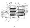
- Fig. 5 is shown in an application of the inventive solution corresponding thermally insulated composite profiles 100 achievable thermal separation. Specifically, there is a temperature of 0 ° C at the profile part 2, which corresponds to the outside, wherein at the opposite profile part 4, a temperature of 20 ° C is present.
- the profile parts 2, 4 of the illustrated composite profiles 100 are each connected via an insulating body 10, which is constructed from a plurality of intermediate walls 11, which are locally connected to each other such that a plurality of air chambers 12 is formed.
- Each of the illustrated composite profiles 100 serves to hold a glass pane 9 shown schematically.
- the insulating body 10 forms a thermal separation plane between the profile parts 2, 4, which limits the heat flow from the outer shell 2 to the inner shell 4 to a minimum.
Landscapes
- Physics & Mathematics (AREA)
- Thermal Sciences (AREA)
- Engineering & Computer Science (AREA)
- Civil Engineering (AREA)
- Structural Engineering (AREA)
- Laminated Bodies (AREA)
- Thermal Insulation (AREA)
Priority Applications (1)
| Application Number | Priority Date | Filing Date | Title |
|---|---|---|---|
| EP08171342A EP2199518A1 (fr) | 2008-12-11 | 2008-12-11 | Profilé composite à isolation thermique et son procédé de fabrication |
Applications Claiming Priority (1)
| Application Number | Priority Date | Filing Date | Title |
|---|---|---|---|
| EP08171342A EP2199518A1 (fr) | 2008-12-11 | 2008-12-11 | Profilé composite à isolation thermique et son procédé de fabrication |
Publications (1)
| Publication Number | Publication Date |
|---|---|
| EP2199518A1 true EP2199518A1 (fr) | 2010-06-23 |
Family
ID=40463850
Family Applications (1)
| Application Number | Title | Priority Date | Filing Date |
|---|---|---|---|
| EP08171342A Withdrawn EP2199518A1 (fr) | 2008-12-11 | 2008-12-11 | Profilé composite à isolation thermique et son procédé de fabrication |
Country Status (1)
| Country | Link |
|---|---|
| EP (1) | EP2199518A1 (fr) |
Cited By (1)
| Publication number | Priority date | Publication date | Assignee | Title |
|---|---|---|---|---|
| CN112709515A (zh) * | 2020-12-28 | 2021-04-27 | 安徽科蓝特铝业有限公司 | 一种浇注式高剪切力电泳隔热型材 |
Citations (4)
| Publication number | Priority date | Publication date | Assignee | Title |
|---|---|---|---|---|
| DE3001402A1 (de) * | 1980-01-16 | 1981-07-23 | Gebrüder Uhl GmbH & Co KG, 7981 Vogt | Waermegedaemmtes verbundprofil |
| DE3042838A1 (de) * | 1980-11-13 | 1982-06-09 | Helmar Dr.Dr. 8530 Neustadt Nahr | Waermeisolierender profilkoerper und verfahren zu seiner herstellung |
| GB2371076A (en) * | 2001-01-16 | 2002-07-17 | Sapa Building Systems Ltd | Insulated frame members |
| DE102004008414A1 (de) * | 2004-02-20 | 2005-09-01 | Ingenieurbüro Dr.-Ing. Harald Schulz | Profilrahmenkonstruktion |
-
2008
- 2008-12-11 EP EP08171342A patent/EP2199518A1/fr not_active Withdrawn
Patent Citations (4)
| Publication number | Priority date | Publication date | Assignee | Title |
|---|---|---|---|---|
| DE3001402A1 (de) * | 1980-01-16 | 1981-07-23 | Gebrüder Uhl GmbH & Co KG, 7981 Vogt | Waermegedaemmtes verbundprofil |
| DE3042838A1 (de) * | 1980-11-13 | 1982-06-09 | Helmar Dr.Dr. 8530 Neustadt Nahr | Waermeisolierender profilkoerper und verfahren zu seiner herstellung |
| GB2371076A (en) * | 2001-01-16 | 2002-07-17 | Sapa Building Systems Ltd | Insulated frame members |
| DE102004008414A1 (de) * | 2004-02-20 | 2005-09-01 | Ingenieurbüro Dr.-Ing. Harald Schulz | Profilrahmenkonstruktion |
Cited By (1)
| Publication number | Priority date | Publication date | Assignee | Title |
|---|---|---|---|---|
| CN112709515A (zh) * | 2020-12-28 | 2021-04-27 | 安徽科蓝特铝业有限公司 | 一种浇注式高剪切力电泳隔热型材 |
Similar Documents
| Publication | Publication Date | Title |
|---|---|---|
| EP2106491B2 (fr) | Profilé en matière plastique pour des éléments de fenêtre, de porte et de façade | |
| EP0153758A2 (fr) | Barre composée, en particulier pour châssis de fenêtre, châssis de porte et volets à rouleau | |
| WO2008071445A1 (fr) | Profilé armé en matière plastique pour des éléments de fenêtre, de porte et de façade | |
| EP1531228A1 (fr) | Profilé composite | |
| EP2476853A1 (fr) | Profil composite pour fenêtres, portes et façades et son procédé de fabrication | |
| EP2576949B1 (fr) | Profile a rupture de pont thermique | |
| EP2864567B1 (fr) | Moulure isolante pour un profilé composite destinée à des fenêtres, des portes ou des éléments de façade et procédé de fabrication d'une telle moulure isolante et d'un profilé composite comprenant une telle moulure isolante | |
| WO2016202438A1 (fr) | Élément isolant | |
| EP3555404B1 (fr) | Profilé composite à isolation thermique en plastique et métal | |
| EP2586953B1 (fr) | Isolateur et profilé à isolation thermique | |
| DE10147409B4 (de) | Wärmeisolierendes, tragfähiges Bauelement und Verfahren zu seiner Herstellung | |
| EP2199518A1 (fr) | Profilé composite à isolation thermique et son procédé de fabrication | |
| DE102011076608A1 (de) | Fügeverbindung für ein Sandwichelement und Verfahren zu seiner Herstellung | |
| AT6230U1 (de) | Bauelement und verwendung eines trägers sowie verfahren zur herstellung eines fassadenelementes | |
| EP1154115A1 (fr) | Profilé creux remplissable par moussage | |
| EP1681404A2 (fr) | Panneau de façade | |
| WO2011104280A1 (fr) | Elément de renforcement pour des profilés de fenêtres en plastique et procédé pour sa fabrication | |
| WO2013017622A1 (fr) | Élément multicouche | |
| EP0556601A1 (fr) | Profil composé | |
| EP1932998A1 (fr) | Profil d'assemblage et procédé de fabrication d'un profil d'assemblage | |
| DE19627121C2 (de) | Verbundprofil | |
| DE19936152C1 (de) | Durchsetzgefügter Hohlbaukörper | |
| DE20100618U1 (de) | Rahmenprofil | |
| WO2018178191A2 (fr) | Plaque de construction résistante à la chaleur et à la compression | |
| EP1681430A2 (fr) | Profilé composite pour cadres d'éléments de paroi, portes et fenêtres |
Legal Events
| Date | Code | Title | Description |
|---|---|---|---|
| PUAI | Public reference made under article 153(3) epc to a published international application that has entered the european phase |
Free format text: ORIGINAL CODE: 0009012 |
|
| 17P | Request for examination filed |
Effective date: 20090629 |
|
| AK | Designated contracting states |
Kind code of ref document: A1 Designated state(s): AT BE BG CH CY CZ DE DK EE ES FI FR GB GR HR HU IE IS IT LI LT LU LV MC MT NL NO PL PT RO SE SI SK TR |
|
| AX | Request for extension of the european patent |
Extension state: AL BA MK RS |
|
| AKY | No designation fees paid | ||
| STAA | Information on the status of an ep patent application or granted ep patent |
Free format text: STATUS: THE APPLICATION IS DEEMED TO BE WITHDRAWN |
|
| 18D | Application deemed to be withdrawn |
Effective date: 20101224 |