EP2199533B1 - Führungsvorrichtung für Schleppseile für Werkzeuge in einem Bohrloch - Google Patents
Führungsvorrichtung für Schleppseile für Werkzeuge in einem Bohrloch Download PDFInfo
- Publication number
- EP2199533B1 EP2199533B1 EP09015721.5A EP09015721A EP2199533B1 EP 2199533 B1 EP2199533 B1 EP 2199533B1 EP 09015721 A EP09015721 A EP 09015721A EP 2199533 B1 EP2199533 B1 EP 2199533B1
- Authority
- EP
- European Patent Office
- Prior art keywords
- hauling rope
- borehole
- guiding device
- tools
- fixing
- Prior art date
- Legal status (The legal status is an assumption and is not a legal conclusion. Google has not performed a legal analysis and makes no representation as to the accuracy of the status listed.)
- Not-in-force
Links
Images


Classifications
-
- B—PERFORMING OPERATIONS; TRANSPORTING
- B66—HOISTING; LIFTING; HAULING
- B66C—CRANES; LOAD-ENGAGING ELEMENTS OR DEVICES FOR CRANES, CAPSTANS, WINCHES, OR TACKLES
- B66C13/00—Other constructional features or details
- B66C13/04—Auxiliary devices for controlling movements of suspended loads, or preventing cable slack
- B66C13/08—Auxiliary devices for controlling movements of suspended loads, or preventing cable slack for depositing loads in desired attitudes or positions
-
- E—FIXED CONSTRUCTIONS
- E21—EARTH OR ROCK DRILLING; MINING
- E21B—EARTH OR ROCK DRILLING; OBTAINING OIL, GAS, WATER, SOLUBLE OR MELTABLE MATERIALS OR A SLURRY OF MINERALS FROM WELLS
- E21B19/00—Handling rods, casings, tubes or the like outside the borehole, e.g. in the derrick; Apparatus for feeding the rods or cables
- E21B19/22—Handling reeled pipe or rod units, e.g. flexible drilling pipes
Definitions
- the present invention relates to a guiding device of a hauling rope, in more detail, a guiding device of a hauling rope that installed at the top of casing, which controls inserting/withdrawing a hauling rope connected with a sonde, measuring instrument, which probes, observes, and examines an underground structure, geological features, or soil conditions etc. within borehole.
- an operation of probing or measuring is performed at desired depth while inserting/withdrawing a measuring instrument, such as a sonde, to acquire various information about the geological formation, such as an underground structure, geological features, or soil conditions and so on.
- the measuring instrument is connected to a hauling rope and the hauling rope allows the measuring instrument to be inserted/withdrawn into/out of a borehole by a winch and a guiding device of a hauling rope.
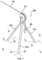
- the guiding device of a hauling rope described above, as shown in FIG. 1 is formed in a bar shape, which includes support members 101a, 101b, 101c of which ends cross each other and a roller 103 where a hauling rope 105 wound around a winch (not shown) is placed, on the joint of the support members 101a, 101b, 101c.
- the guiding device of a hauling rope 100 is installed at the constant height of a borehole (not shown) drilled to observe or examine the borehole conditions and in situ physical properties, disposing the plurality of support members 101a, 101b, 101c at one side around the borehole (not shown) to cross each other, disposing the roller 103 on the joint of the support members, and then positioning the hauling rope 105 on the roller 103.
- a measuring instrument such as a sonde 109, is connected to an end of the hauling rope 105 wound around the roller 103, that is, the end of the hauling rope 105 which is put into the borehole (not shown).
- a worker or an observer on the ground observes or measures the conditions and in situ physical properties of subsurface formation by inserting the sonde 109 connected to the end of the hauling rope 105 into the borehole (not shown) using a winch.
- the borehole drilled to observe and measure the subsurface formation using the sonde connected to the hauling rope may be clogged or collapsed, and the surface water may be flowed into a borehole.
- a guiding device of a hauling rope for tools in a borehole according to the preamble of claim 1 is described in US 3,104,094 A .
- the moving member can be moved from/into an open position, with the hauling rope being passed through without any guiding, into/from an operating position, with the hauling rope passing through the guide into the borehole.
- a measuring instrument such as a sonde
- the hauling rope guiding device can be easily attached to the borehole casing by the pressing member and the fastening plate, so that the hauling rope can be easily adjusted relative to the borehole by moving the hauling rope guide body relative to the cradle fixed to the borehole casing by the pressing member and the fastening plate.
- the cradle can be easily attached to the borehole casing by the pressing member, it is possible to observe and examine the subsurface geological information, even though the ground around a borehole is rough and different gradation or the height of casing is high. Further, since the distance can be adjusted while the hauling rope guide body where the hauling rope is placed moves forward/backward with respect to the cradle, it is possible to position the measuring device, such as a sonde, which is connected to the hauling rope, to the center of the borehole regardless of the diameter of the borehole.
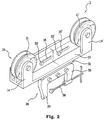
- FIG. 2 is a front perspective view schematically showing a guiding device of a hauling rope for tools in a borehole according to the present invention
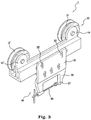
- FIG. 3 is a rear perspective view schematically showing the guiding device of a hauling rope for tools in a borehole according to the present invention
- FIG. 4 is a side view schematically showing the guiding device of a hauling rope for tools in a borehole according to the present invention
- FIG. 5 is a perspective view illustrating the adjustment of a position of the guiding device of a hauling rope for tools in a borehole according to the present invention
- FIG. 6 is a perspective view schematically showing when the guiding device of a hauling rope for tools in a borehole according to the present invention is installed.
- a guiding device of a hauling rope for tools in a borehole includes a hauling rope guide body 10 and a cradle 30.
- the hauling rope guide body 10 includes a pair or rollers 11, 11' for inserting/withdrawing a hauling rope 3 wound around a winch (not shown) into/out of the ground, an L-shaped moving member 13 having fixing portions 14, 14' for fixing the pair or rollers 11, 11' at both ends, and one or more distance adjusting holes 16, 16' formed in a slot shape through one side of the moving member 13.
- the rollers 11, 11' and the distance adjusting holes 16, 16' are arranged in the longitudinal direction of the moving member 13.
- the hauling guide body 10 can easily insert/withdraw the hauling rope 3 wound around the winch into/out of the ground, and a worker or an observer monitors conditions inside the ground through a sonde 7, which is a measuring instrument connected to the end of the hauling rope 3.
- the hauling rope 3 is provided with an electricity or signal transmitting/receiving cable (not shown) in order for the worker or the observer to monitor conditions inside the ground through the sonde 7.
- the cradle 30 is provided to be attached to a cylindrical borehole casing 5 disposed at the inlet of the borehole bored by a drilling rig (not shown) to prevent the borehole from being clogged, when the soil caves in or collapses.
- the cradle 30 includes a fixing member 31 formed in a T-shape to be attached to the lower side of the moving member 13 of the guiding hauling body 10 and a fastening unit 35 attached to the lower side of the fixing member 31.
- the fixing member 31 is fastened and fixed to the moving member 13 of the hauling rope body 10 by fixing bolts 33, 33' and the fixing bolts 33, 33' are fixed in the distance adjusting holes 16, 16' formed in the longitudinal direction through the moving member 13 by fixing nuts 32, 32' .
- the moving member 13 can be moved forward/backward from the fixing member 31 and fixed after being moved forward/backward, by tightening or loosening the fixing bolts 33, 33'.
- the cradle 30 can be moved forward/backward with respect to the hauling rope body 10 by moving the moving member 13 forward/backward on the fixing member 31 after partially loosening the fixing bolts 33, 33' inserted in the distance adjusting holes 16, 16' from the fixing nuts 32, 32', stopping the moving member 13 at a predetermined position while moving it forward/backward, and then moving and fixing the moving member 13 from the fixing member 31 by tightening the fixing bolts 33, 33' in the distance adjusting holes 16, 16'.
- the fastening unit 35 is disposed beneath the fixing member 31, and includes a pressing member 36 that moves forward/backward while turning and a fastening plate 37 that the end of the pressing member 36 contacts with when moving forward.
- a hole such as a borehole (not shown), is formed by a drilling rig at a predetermined location on the ground to observe and examine the subsurface geological information.
- a cylindrical borehole casing 5 for preventing the borehole from being clogged or collapsed, and inflow of surface water at the top of borehole.
- the guiding device of a hauling rope for tools in a borehole 1 according to the present invention is attached to the edge of the borehole casing 5.
- the guiding device of a hauling rope for tools in a borehole 1 is attached to the borehole casing 5 by positioning the pressing member 36 and the fastening plate 37 of the fastening unit 35 of the guiding device of a hauling rope for tools in a borehole 1 at a predetermined distance, positioning the fastening unit 35 to the edge of the borehole casing 5, and then turning the pressing member 36 of the fastening unit 35 to move forward to the fastening plate 37.
- the hauling rope 3 wound around the winch (not shown) on the ground is placed on the pair of rollers 11, 11' arranged in the longitudinal direction in the guiding device of a hauling rope for tools in a borehole 1.
- the sonde 7 that is a measuring instrument for observing and examining the subsurface geological information is connected to the end of the hauling rope 3 wound around the winch and inserted inside the borehole through the borehole casing 5.
- the sonde 7 connected to the hauling rope 3 that is inserted into the borehole by the pair of rollers 11, 11' is positioned at the center of the borehole casing 5, by combining and fixing the hauling rope guide body 10 and the cradle 30, loosening the fixing bolts 33, 33' in the distance adjusting holes 16, 16' of the moving member 13 of the hauling guide body 10 from the fixing nuts 32, 32', and then moving the hauling rope guide body 10 forward/backward in the longitudinal direction of the cradle 30.
- a worker or an observer on the ground observes or examines the subsurface geological information by operating the winch such that the sonde 7 connected to the end of the hauling rope 3 is inserted in the borehole.
- the conditions inside the borehole observed and examined by the sonde 7 are monitored and recorded by the measurement console connected with a cable disposed in the hauling rope 3 or specifically provided.
Landscapes
- Engineering & Computer Science (AREA)
- Mechanical Engineering (AREA)
- Geology (AREA)
- Life Sciences & Earth Sciences (AREA)
- Mining & Mineral Resources (AREA)
- Environmental & Geological Engineering (AREA)
- Fluid Mechanics (AREA)
- Physics & Mathematics (AREA)
- General Life Sciences & Earth Sciences (AREA)
- Geochemistry & Mineralogy (AREA)
- Geophysics And Detection Of Objects (AREA)
- Investigation Of Foundation Soil And Reinforcement Of Foundation Soil By Compacting Or Drainage (AREA)
- Earth Drilling (AREA)
Claims (5)
- Führungsvorrichtung für ein Zugseil (3) für Werkzeuge in einem Bohrloch, die das Zugseil (3), das mit einer Sonde (7) ausgestattet ist, um die unterirdischen geologischen Informationen an dem Ende zu beobachten und zu messen, und das um eine Winde gewickelt ist, in ein Bohrloch einführt/aus dem Bohrloch herauszieht, wo eine Bohrlochverkleidung (5) angeordnet ist, wobei die Führungsvorrichtung Folgendes umfasst:einen Zugseilführungskörper (10), der ein Paar Rollen (11, 11') besitzt, wo das Zugseil (3) zu positionieren ist, undein Bewegungselement (13) mit Befestigungsteilen (14, 14'), die das Paar Rollen (11, 11') an beiden Enden fixieren; undeinen Rollenhalter (30), der an der Bohrlochverkleidung (5) anzubringen ist und ein Befestigungselement (31), das an der unteren Seite des Bewegungselements (13) angebracht ist, und eine Befestigungseinheit (35), die an der unteren Seite des Befestigungselements (31) angebracht ist, enthält, dadurch gekennzeichnet, dassdie Befestigungseinheit (35) ein Druckelement (36), das sich vorwärts/rückwärts bewegt, indem es gedreht wird, und eine Befestigungsplatte (37), die das Ende des Druckelements (36) berührt, wenn es sich vorwärts bewegt, enthält.
- Führungsvorrichtung eines Zugseils für Werkzeuge in einem Bohrloch nach Anspruch 1, wobei mindestens ein oder mehrere Abstandsanpassungslöcher (16, 16') in einer Schlitzform durch eine Seite des Bewegungselements (13) gebildet sind.
- Führungsvorrichtung eines Zugseils für Werkzeuge in einem Bohrloch nach Anspruch 2, wobei das Befestigungselement (31) befestigt ist und an dem Bewegungselement (13) durch Fixierbolzen (33, 33'), die in die Abstandsanpassungslöcher (16, 16') eingefügt sind, und Fixiernuten (32, 32') fixiert ist.
- Führungsvorrichtung eines Zugseils für Werkzeuge in einem Bohrloch nach Anspruch 3, wobei der Zugseilführungskörper (10) in Bezug auf den Rollenhalter (30) durch Anziehen oder Lösen der Fixerbolzen (33, 33') und der Fixiernuten (32, 32') vorwärts/rückwärts bewegt wird.
- Führungsvorrichtung eines Zugseils für Werkzeuge in einem Bohrloch nach Anspruch 1, wobei die Längen der Fixierteile (14, 14') des Zugseilführungskörpers (10) geändert werden können.
Applications Claiming Priority (1)
| Application Number | Priority Date | Filing Date | Title |
|---|---|---|---|
| KR1020080131269A KR101056768B1 (ko) | 2008-12-22 | 2008-12-22 | 공내 장치 견인줄 유도 거치대 |
Publications (3)
| Publication Number | Publication Date |
|---|---|
| EP2199533A2 EP2199533A2 (de) | 2010-06-23 |
| EP2199533A3 EP2199533A3 (de) | 2014-04-09 |
| EP2199533B1 true EP2199533B1 (de) | 2018-04-25 |
Family
ID=41586150
Family Applications (1)
| Application Number | Title | Priority Date | Filing Date |
|---|---|---|---|
| EP09015721.5A Not-in-force EP2199533B1 (de) | 2008-12-22 | 2009-12-18 | Führungsvorrichtung für Schleppseile für Werkzeuge in einem Bohrloch |
Country Status (4)
| Country | Link |
|---|---|
| US (1) | US8282081B2 (de) |
| EP (1) | EP2199533B1 (de) |
| JP (1) | JP5424399B2 (de) |
| KR (1) | KR101056768B1 (de) |
Families Citing this family (8)
| Publication number | Priority date | Publication date | Assignee | Title |
|---|---|---|---|---|
| KR101237925B1 (ko) * | 2011-03-09 | 2013-02-27 | 한국지질자원연구원 | 지하수 프로파일 모니터링 시스템 |
| CN102287144B (zh) * | 2011-06-09 | 2013-04-17 | 中国石油化工股份有限公司 | 井用管线导向器 |
| KR101359489B1 (ko) * | 2011-10-11 | 2014-02-07 | 한국지질자원연구원 | 케이싱 거치식 손데 가이드장치 |
| EP2698499B1 (de) * | 2012-08-13 | 2014-11-05 | Bauer Spezialtiefbau GmbH | Verfahren und Vorrichtung zum Erstellen und Vermessen eines Bohrloches |
| CN106225771A (zh) * | 2016-08-29 | 2016-12-14 | 中航勘察设计研究院有限公司 | 一种用于测斜仪的辅助测量装置 |
| CN109505586B (zh) * | 2018-11-06 | 2023-10-03 | 能诚集团有限公司 | 一种井下探测装置 |
| CN114922561B (zh) * | 2022-05-18 | 2023-06-06 | 中国地质大学(北京) | 一种基于地质勘探的便携式钻机 |
| CN114684715B (zh) * | 2022-05-31 | 2022-08-26 | 江苏沛泽机械科技有限公司 | 一种矿山机械金属钻头吊运装置 |
Family Cites Families (17)
| Publication number | Priority date | Publication date | Assignee | Title |
|---|---|---|---|---|
| US3104094A (en) * | 1961-08-17 | 1963-09-17 | Rowan Drilling Company Inc | Wire line guide apparatus |
| US3589642A (en) * | 1969-02-26 | 1971-06-29 | Schlumberger Technology Corp | Fleet angle controller |
| US3871621A (en) * | 1973-09-21 | 1975-03-18 | Jackson Communication Corp | Cable chute |
| US3834670A (en) * | 1973-10-11 | 1974-09-10 | Reel Power Equipment Inc | Boat anchor winch mechanism |
| US4123041A (en) * | 1977-07-12 | 1978-10-31 | Bucknall Arthur H | Lifting tackle |
| JPS5931691U (ja) * | 1982-08-20 | 1984-02-27 | 日本重化学工業株式会社 | 坑井内検層用巻上げ装置 |
| EP0147487A1 (de) * | 1983-12-29 | 1985-07-10 | Man Gutehoffnungshütte Gmbh | Einrichtung zum Heben und Senken von Prospektzügen einer Theaterbühne |
| US4986351A (en) * | 1989-12-05 | 1991-01-22 | Marshall E. Wisner | Portable pump removal equipment |
| CA2054039A1 (en) * | 1990-10-23 | 1992-04-24 | Gerald Crouse | Well pipe hoist and hoisting method |
| JPH0496011U (de) * | 1991-01-10 | 1992-08-20 | ||
| US5423438A (en) * | 1993-09-13 | 1995-06-13 | Harnischfeger Corporation | Crane with redundant hoist arrangement and method of using same |
| JPH10300461A (ja) * | 1997-04-21 | 1998-11-13 | Kaijo Corp | 超音波孔壁測定器用センサ巻上機 |
| CA2322132A1 (en) * | 2000-10-13 | 2002-04-13 | Unique Concepts Ltd. | Shock absorber for hoist |
| US6631885B2 (en) * | 2001-10-11 | 2003-10-14 | D. Carl Halas | Arborist limb lowering device and method |
| US7134645B1 (en) * | 2003-02-05 | 2006-11-14 | Advanced Design Consulting Usa | Winch assembly for use with synthetic ropes |
| KR200419423Y1 (ko) * | 2006-01-23 | 2006-06-20 | 임경순 | 클램프를 응용한 케이블 지지대 |
| KR100745836B1 (ko) * | 2006-06-16 | 2007-08-02 | 한국지질자원연구원 | 모노 포드 |
-
2008
- 2008-12-22 KR KR1020080131269A patent/KR101056768B1/ko active Active
-
2009
- 2009-12-17 JP JP2009286802A patent/JP5424399B2/ja not_active Expired - Fee Related
- 2009-12-17 US US12/640,979 patent/US8282081B2/en not_active Expired - Fee Related
- 2009-12-18 EP EP09015721.5A patent/EP2199533B1/de not_active Not-in-force
Non-Patent Citations (1)
| Title |
|---|
| None * |
Also Published As
| Publication number | Publication date |
|---|---|
| KR101056768B1 (ko) | 2011-08-12 |
| JP2010144508A (ja) | 2010-07-01 |
| EP2199533A3 (de) | 2014-04-09 |
| US20100295006A1 (en) | 2010-11-25 |
| EP2199533A2 (de) | 2010-06-23 |
| KR20100072766A (ko) | 2010-07-01 |
| US8282081B2 (en) | 2012-10-09 |
| JP5424399B2 (ja) | 2014-02-26 |
Similar Documents
| Publication | Publication Date | Title |
|---|---|---|
| US8282081B2 (en) | Guiding device of hauling rope for tools in borehole | |
| KR101029283B1 (ko) | 인발축 자동 조정 기능의 록볼트 인발시험장치 | |
| CA2593959A1 (en) | Apparatus and methods to perform downhole measurements associated with subterranean formation evaluation | |
| CA2913794C (en) | Method and system for monitoring and managing fiber cable slack in a coiled tubing | |
| GB2349660A (en) | Seabed penetrator and analyser | |
| JP4918671B2 (ja) | 坑井予備調査用独立形計測兼信号処理プローブ | |
| US11384634B2 (en) | Maintenance device and method for determining the position of a blockage point of a tubular member | |
| CN102162234A (zh) | 一种岩土体表面位移实时监测装置及监测方法 | |
| KR101823808B1 (ko) | 드릴링 시스템의 공구 홀더를 위한 잠금 장치 및 잠금 방법 | |
| KR101488290B1 (ko) | 잭업 리그용 스퍼드 장치 | |
| JP2009299316A (ja) | 変位測定装置及び変位測定方法 | |
| EA001047B1 (ru) | Устройство для исследования формаций в земле | |
| RU2570688C2 (ru) | Способ и система для разработки и измерения буровой скважины | |
| US6644423B2 (en) | Wireline system for multiple direct push tool usage | |
| US6327919B1 (en) | Method for taking a soil sample from a horizontal borehole | |
| US8272260B2 (en) | Method and apparatus for formation evaluation after drilling | |
| JP4806116B2 (ja) | ボードドレーンの打止め管理法及びボードドレーン施工機 | |
| DE19549250C1 (de) | Vorrichtung zur Ortung von im Boden verborgener Munition | |
| KR100745836B1 (ko) | 모노 포드 | |
| DE102009007197B4 (de) | Teleskopierbare Meßvorrichtung | |
| CN218995257U (zh) | 一种斜孔声波测试推送装置及斜孔声波测试设备 | |
| KR101703033B1 (ko) | 지하수 심정 조사용 전선케이블 안내장치 | |
| KR101359489B1 (ko) | 케이싱 거치식 손데 가이드장치 | |
| KR100403445B1 (ko) | 텐션 미터 윈치 | |
| JP3465006B2 (ja) | 縦穴の壁面状態測定装置 |
Legal Events
| Date | Code | Title | Description |
|---|---|---|---|
| PUAI | Public reference made under article 153(3) epc to a published international application that has entered the european phase |
Free format text: ORIGINAL CODE: 0009012 |
|
| AK | Designated contracting states |
Kind code of ref document: A2 Designated state(s): AT BE BG CH CY CZ DE DK EE ES FI FR GB GR HR HU IE IS IT LI LT LU LV MC MK MT NL NO PL PT RO SE SI SK SM TR |
|
| AX | Request for extension of the european patent |
Extension state: AL BA RS |
|
| PUAL | Search report despatched |
Free format text: ORIGINAL CODE: 0009013 |
|
| AK | Designated contracting states |
Kind code of ref document: A3 Designated state(s): AT BE BG CH CY CZ DE DK EE ES FI FR GB GR HR HU IE IS IT LI LT LU LV MC MK MT NL NO PL PT RO SE SI SK SM TR |
|
| AX | Request for extension of the european patent |
Extension state: AL BA RS |
|
| RIC1 | Information provided on ipc code assigned before grant |
Ipc: E21B 19/22 20060101AFI20140228BHEP |
|
| 17P | Request for examination filed |
Effective date: 20141009 |
|
| RBV | Designated contracting states (corrected) |
Designated state(s): AT BE BG CH CY CZ DE DK EE ES FI FR GB GR HR HU IE IS IT LI LT LU LV MC MK MT NL NO PL PT RO SE SI SK SM TR |
|
| GRAP | Despatch of communication of intention to grant a patent |
Free format text: ORIGINAL CODE: EPIDOSNIGR1 |
|
| INTG | Intention to grant announced |
Effective date: 20171204 |
|
| GRAA | (expected) grant |
Free format text: ORIGINAL CODE: 0009210 |
|
| GRAS | Grant fee paid |
Free format text: ORIGINAL CODE: EPIDOSNIGR3 |
|
| AK | Designated contracting states |
Kind code of ref document: B1 Designated state(s): AT BE BG CH CY CZ DE DK EE ES FI FR GB GR HR HU IE IS IT LI LT LU LV MC MK MT NL NO PL PT RO SE SI SK SM TR |
|
| REG | Reference to a national code |
Ref country code: GB Ref legal event code: FG4D |
|
| REG | Reference to a national code |
Ref country code: CH Ref legal event code: EP |
|
| REG | Reference to a national code |
Ref country code: AT Ref legal event code: REF Ref document number: 993116 Country of ref document: AT Kind code of ref document: T Effective date: 20180515 |
|
| REG | Reference to a national code |
Ref country code: IE Ref legal event code: FG4D |
|
| REG | Reference to a national code |
Ref country code: DE Ref legal event code: R096 Ref document number: 602009051937 Country of ref document: DE |
|
| REG | Reference to a national code |
Ref country code: NL Ref legal event code: MP Effective date: 20180425 |
|
| REG | Reference to a national code |
Ref country code: LT Ref legal event code: MG4D |
|
| PG25 | Lapsed in a contracting state [announced via postgrant information from national office to epo] |
Ref country code: NL Free format text: LAPSE BECAUSE OF FAILURE TO SUBMIT A TRANSLATION OF THE DESCRIPTION OR TO PAY THE FEE WITHIN THE PRESCRIBED TIME-LIMIT Effective date: 20180425 |
|
| PG25 | Lapsed in a contracting state [announced via postgrant information from national office to epo] |
Ref country code: ES Free format text: LAPSE BECAUSE OF FAILURE TO SUBMIT A TRANSLATION OF THE DESCRIPTION OR TO PAY THE FEE WITHIN THE PRESCRIBED TIME-LIMIT Effective date: 20180425 Ref country code: SE Free format text: LAPSE BECAUSE OF FAILURE TO SUBMIT A TRANSLATION OF THE DESCRIPTION OR TO PAY THE FEE WITHIN THE PRESCRIBED TIME-LIMIT Effective date: 20180425 Ref country code: LT Free format text: LAPSE BECAUSE OF FAILURE TO SUBMIT A TRANSLATION OF THE DESCRIPTION OR TO PAY THE FEE WITHIN THE PRESCRIBED TIME-LIMIT Effective date: 20180425 Ref country code: PL Free format text: LAPSE BECAUSE OF FAILURE TO SUBMIT A TRANSLATION OF THE DESCRIPTION OR TO PAY THE FEE WITHIN THE PRESCRIBED TIME-LIMIT Effective date: 20180425 Ref country code: BG Free format text: LAPSE BECAUSE OF FAILURE TO SUBMIT A TRANSLATION OF THE DESCRIPTION OR TO PAY THE FEE WITHIN THE PRESCRIBED TIME-LIMIT Effective date: 20180725 Ref country code: FI Free format text: LAPSE BECAUSE OF FAILURE TO SUBMIT A TRANSLATION OF THE DESCRIPTION OR TO PAY THE FEE WITHIN THE PRESCRIBED TIME-LIMIT Effective date: 20180425 Ref country code: NO Free format text: LAPSE BECAUSE OF FAILURE TO SUBMIT A TRANSLATION OF THE DESCRIPTION OR TO PAY THE FEE WITHIN THE PRESCRIBED TIME-LIMIT Effective date: 20180725 |
|
| PG25 | Lapsed in a contracting state [announced via postgrant information from national office to epo] |
Ref country code: LV Free format text: LAPSE BECAUSE OF FAILURE TO SUBMIT A TRANSLATION OF THE DESCRIPTION OR TO PAY THE FEE WITHIN THE PRESCRIBED TIME-LIMIT Effective date: 20180425 Ref country code: GR Free format text: LAPSE BECAUSE OF FAILURE TO SUBMIT A TRANSLATION OF THE DESCRIPTION OR TO PAY THE FEE WITHIN THE PRESCRIBED TIME-LIMIT Effective date: 20180726 Ref country code: HR Free format text: LAPSE BECAUSE OF FAILURE TO SUBMIT A TRANSLATION OF THE DESCRIPTION OR TO PAY THE FEE WITHIN THE PRESCRIBED TIME-LIMIT Effective date: 20180425 |
|
| REG | Reference to a national code |
Ref country code: AT Ref legal event code: MK05 Ref document number: 993116 Country of ref document: AT Kind code of ref document: T Effective date: 20180425 |
|
| PG25 | Lapsed in a contracting state [announced via postgrant information from national office to epo] |
Ref country code: PT Free format text: LAPSE BECAUSE OF FAILURE TO SUBMIT A TRANSLATION OF THE DESCRIPTION OR TO PAY THE FEE WITHIN THE PRESCRIBED TIME-LIMIT Effective date: 20180827 |
|
| REG | Reference to a national code |
Ref country code: DE Ref legal event code: R097 Ref document number: 602009051937 Country of ref document: DE |
|
| PG25 | Lapsed in a contracting state [announced via postgrant information from national office to epo] |
Ref country code: SK Free format text: LAPSE BECAUSE OF FAILURE TO SUBMIT A TRANSLATION OF THE DESCRIPTION OR TO PAY THE FEE WITHIN THE PRESCRIBED TIME-LIMIT Effective date: 20180425 Ref country code: EE Free format text: LAPSE BECAUSE OF FAILURE TO SUBMIT A TRANSLATION OF THE DESCRIPTION OR TO PAY THE FEE WITHIN THE PRESCRIBED TIME-LIMIT Effective date: 20180425 Ref country code: AT Free format text: LAPSE BECAUSE OF FAILURE TO SUBMIT A TRANSLATION OF THE DESCRIPTION OR TO PAY THE FEE WITHIN THE PRESCRIBED TIME-LIMIT Effective date: 20180425 Ref country code: DK Free format text: LAPSE BECAUSE OF FAILURE TO SUBMIT A TRANSLATION OF THE DESCRIPTION OR TO PAY THE FEE WITHIN THE PRESCRIBED TIME-LIMIT Effective date: 20180425 Ref country code: RO Free format text: LAPSE BECAUSE OF FAILURE TO SUBMIT A TRANSLATION OF THE DESCRIPTION OR TO PAY THE FEE WITHIN THE PRESCRIBED TIME-LIMIT Effective date: 20180425 Ref country code: CZ Free format text: LAPSE BECAUSE OF FAILURE TO SUBMIT A TRANSLATION OF THE DESCRIPTION OR TO PAY THE FEE WITHIN THE PRESCRIBED TIME-LIMIT Effective date: 20180425 |
|
| PG25 | Lapsed in a contracting state [announced via postgrant information from national office to epo] |
Ref country code: IT Free format text: LAPSE BECAUSE OF FAILURE TO SUBMIT A TRANSLATION OF THE DESCRIPTION OR TO PAY THE FEE WITHIN THE PRESCRIBED TIME-LIMIT Effective date: 20180425 Ref country code: SM Free format text: LAPSE BECAUSE OF FAILURE TO SUBMIT A TRANSLATION OF THE DESCRIPTION OR TO PAY THE FEE WITHIN THE PRESCRIBED TIME-LIMIT Effective date: 20180425 |
|
| PLBE | No opposition filed within time limit |
Free format text: ORIGINAL CODE: 0009261 |
|
| STAA | Information on the status of an ep patent application or granted ep patent |
Free format text: STATUS: NO OPPOSITION FILED WITHIN TIME LIMIT |
|
| 26N | No opposition filed |
Effective date: 20190128 |
|
| PG25 | Lapsed in a contracting state [announced via postgrant information from national office to epo] |
Ref country code: SI Free format text: LAPSE BECAUSE OF FAILURE TO SUBMIT A TRANSLATION OF THE DESCRIPTION OR TO PAY THE FEE WITHIN THE PRESCRIBED TIME-LIMIT Effective date: 20180425 |
|
| REG | Reference to a national code |
Ref country code: CH Ref legal event code: PL |
|
| PG25 | Lapsed in a contracting state [announced via postgrant information from national office to epo] |
Ref country code: LU Free format text: LAPSE BECAUSE OF NON-PAYMENT OF DUE FEES Effective date: 20181218 Ref country code: MC Free format text: LAPSE BECAUSE OF FAILURE TO SUBMIT A TRANSLATION OF THE DESCRIPTION OR TO PAY THE FEE WITHIN THE PRESCRIBED TIME-LIMIT Effective date: 20180425 |
|
| REG | Reference to a national code |
Ref country code: IE Ref legal event code: MM4A |
|
| REG | Reference to a national code |
Ref country code: BE Ref legal event code: MM Effective date: 20181231 |
|
| PG25 | Lapsed in a contracting state [announced via postgrant information from national office to epo] |
Ref country code: FR Free format text: LAPSE BECAUSE OF NON-PAYMENT OF DUE FEES Effective date: 20181231 Ref country code: IE Free format text: LAPSE BECAUSE OF NON-PAYMENT OF DUE FEES Effective date: 20181218 |
|
| PG25 | Lapsed in a contracting state [announced via postgrant information from national office to epo] |
Ref country code: BE Free format text: LAPSE BECAUSE OF NON-PAYMENT OF DUE FEES Effective date: 20181231 |
|
| PG25 | Lapsed in a contracting state [announced via postgrant information from national office to epo] |
Ref country code: CH Free format text: LAPSE BECAUSE OF NON-PAYMENT OF DUE FEES Effective date: 20181231 Ref country code: LI Free format text: LAPSE BECAUSE OF NON-PAYMENT OF DUE FEES Effective date: 20181231 |
|
| PG25 | Lapsed in a contracting state [announced via postgrant information from national office to epo] |
Ref country code: MT Free format text: LAPSE BECAUSE OF NON-PAYMENT OF DUE FEES Effective date: 20181218 |
|
| PG25 | Lapsed in a contracting state [announced via postgrant information from national office to epo] |
Ref country code: TR Free format text: LAPSE BECAUSE OF FAILURE TO SUBMIT A TRANSLATION OF THE DESCRIPTION OR TO PAY THE FEE WITHIN THE PRESCRIBED TIME-LIMIT Effective date: 20180425 |
|
| PG25 | Lapsed in a contracting state [announced via postgrant information from national office to epo] |
Ref country code: MK Free format text: LAPSE BECAUSE OF NON-PAYMENT OF DUE FEES Effective date: 20180425 Ref country code: HU Free format text: LAPSE BECAUSE OF FAILURE TO SUBMIT A TRANSLATION OF THE DESCRIPTION OR TO PAY THE FEE WITHIN THE PRESCRIBED TIME-LIMIT; INVALID AB INITIO Effective date: 20091218 Ref country code: CY Free format text: LAPSE BECAUSE OF FAILURE TO SUBMIT A TRANSLATION OF THE DESCRIPTION OR TO PAY THE FEE WITHIN THE PRESCRIBED TIME-LIMIT Effective date: 20180425 |
|
| PG25 | Lapsed in a contracting state [announced via postgrant information from national office to epo] |
Ref country code: IS Free format text: LAPSE BECAUSE OF FAILURE TO SUBMIT A TRANSLATION OF THE DESCRIPTION OR TO PAY THE FEE WITHIN THE PRESCRIBED TIME-LIMIT Effective date: 20180825 |
|
| PGFP | Annual fee paid to national office [announced via postgrant information from national office to epo] |
Ref country code: GB Payment date: 20221005 Year of fee payment: 14 Ref country code: DE Payment date: 20220920 Year of fee payment: 14 |
|
| REG | Reference to a national code |
Ref country code: DE Ref legal event code: R119 Ref document number: 602009051937 Country of ref document: DE |
|
| GBPC | Gb: european patent ceased through non-payment of renewal fee |
Effective date: 20231218 |
|
| PG25 | Lapsed in a contracting state [announced via postgrant information from national office to epo] |
Ref country code: DE Free format text: LAPSE BECAUSE OF NON-PAYMENT OF DUE FEES Effective date: 20240702 |
|
| PG25 | Lapsed in a contracting state [announced via postgrant information from national office to epo] |
Ref country code: GB Free format text: LAPSE BECAUSE OF NON-PAYMENT OF DUE FEES Effective date: 20231218 |
|
| PG25 | Lapsed in a contracting state [announced via postgrant information from national office to epo] |
Ref country code: GB Free format text: LAPSE BECAUSE OF NON-PAYMENT OF DUE FEES Effective date: 20231218 Ref country code: DE Free format text: LAPSE BECAUSE OF NON-PAYMENT OF DUE FEES Effective date: 20240702 |