EP2199577A1 - Estimation du débit massique d'air dans le circuit de recirculation des gaz d'échappement - Google Patents
Estimation du débit massique d'air dans le circuit de recirculation des gaz d'échappement Download PDFInfo
- Publication number
- EP2199577A1 EP2199577A1 EP09177183A EP09177183A EP2199577A1 EP 2199577 A1 EP2199577 A1 EP 2199577A1 EP 09177183 A EP09177183 A EP 09177183A EP 09177183 A EP09177183 A EP 09177183A EP 2199577 A1 EP2199577 A1 EP 2199577A1
- Authority
- EP
- European Patent Office
- Prior art keywords
- flow
- egr
- engine
- fresh air
- air flow
- Prior art date
- Legal status (The legal status is an assumption and is not a legal conclusion. Google has not performed a legal analysis and makes no representation as to the accuracy of the status listed.)
- Withdrawn
Links
- 238000002485 combustion reaction Methods 0.000 claims abstract description 39
- 238000000034 method Methods 0.000 claims description 7
- 239000003085 diluting agent Substances 0.000 claims description 3
- 238000007599 discharging Methods 0.000 claims description 2
- 239000000446 fuel Substances 0.000 abstract description 11
- 230000029058 respiratory gaseous exchange Effects 0.000 abstract description 2
- 238000005259 measurement Methods 0.000 description 11
- 239000007789 gas Substances 0.000 description 8
- IJGRMHOSHXDMSA-UHFFFAOYSA-N Atomic nitrogen Chemical compound N#N IJGRMHOSHXDMSA-UHFFFAOYSA-N 0.000 description 4
- 230000006835 compression Effects 0.000 description 4
- 238000007906 compression Methods 0.000 description 4
- 230000002411 adverse Effects 0.000 description 3
- QVGXLLKOCUKJST-UHFFFAOYSA-N atomic oxygen Chemical compound [O] QVGXLLKOCUKJST-UHFFFAOYSA-N 0.000 description 2
- 229910052757 nitrogen Inorganic materials 0.000 description 2
- 239000001301 oxygen Substances 0.000 description 2
- 229910052760 oxygen Inorganic materials 0.000 description 2
- 238000005086 pumping Methods 0.000 description 2
- 230000006978 adaptation Effects 0.000 description 1
- 238000013459 approach Methods 0.000 description 1
- 239000003054 catalyst Substances 0.000 description 1
- 230000001010 compromised effect Effects 0.000 description 1
- 239000000470 constituent Substances 0.000 description 1
- 230000007812 deficiency Effects 0.000 description 1
- 230000000694 effects Effects 0.000 description 1
- 230000007613 environmental effect Effects 0.000 description 1
- 238000007254 oxidation reaction Methods 0.000 description 1
- 230000009467 reduction Effects 0.000 description 1
- 230000001629 suppression Effects 0.000 description 1
Images
Classifications
-
- F—MECHANICAL ENGINEERING; LIGHTING; HEATING; WEAPONS; BLASTING
- F02—COMBUSTION ENGINES; HOT-GAS OR COMBUSTION-PRODUCT ENGINE PLANTS
- F02D—CONTROLLING COMBUSTION ENGINES
- F02D41/00—Electrical control of supply of combustible mixture or its constituents
- F02D41/02—Circuit arrangements for generating control signals
- F02D41/18—Circuit arrangements for generating control signals by measuring intake air flow
-
- F—MECHANICAL ENGINEERING; LIGHTING; HEATING; WEAPONS; BLASTING
- F02—COMBUSTION ENGINES; HOT-GAS OR COMBUSTION-PRODUCT ENGINE PLANTS
- F02B—INTERNAL-COMBUSTION PISTON ENGINES; COMBUSTION ENGINES IN GENERAL
- F02B37/00—Engines characterised by provision of pumps driven at least for part of the time by exhaust
- F02B37/004—Engines characterised by provision of pumps driven at least for part of the time by exhaust with exhaust drives arranged in series
-
- F—MECHANICAL ENGINEERING; LIGHTING; HEATING; WEAPONS; BLASTING
- F02—COMBUSTION ENGINES; HOT-GAS OR COMBUSTION-PRODUCT ENGINE PLANTS
- F02B—INTERNAL-COMBUSTION PISTON ENGINES; COMBUSTION ENGINES IN GENERAL
- F02B37/00—Engines characterised by provision of pumps driven at least for part of the time by exhaust
- F02B37/013—Engines characterised by provision of pumps driven at least for part of the time by exhaust with exhaust-driven pumps arranged in series
-
- F—MECHANICAL ENGINEERING; LIGHTING; HEATING; WEAPONS; BLASTING
- F02—COMBUSTION ENGINES; HOT-GAS OR COMBUSTION-PRODUCT ENGINE PLANTS
- F02D—CONTROLLING COMBUSTION ENGINES
- F02D41/00—Electrical control of supply of combustible mixture or its constituents
- F02D41/0025—Controlling engines characterised by use of non-liquid fuels, pluralities of fuels, or non-fuel substances added to the combustible mixtures
- F02D41/0047—Controlling exhaust gas recirculation [EGR]
- F02D41/0065—Specific aspects of external EGR control
- F02D41/0072—Estimating, calculating or determining the EGR rate, amount or flow
-
- F—MECHANICAL ENGINEERING; LIGHTING; HEATING; WEAPONS; BLASTING
- F02—COMBUSTION ENGINES; HOT-GAS OR COMBUSTION-PRODUCT ENGINE PLANTS
- F02D—CONTROLLING COMBUSTION ENGINES
- F02D2200/00—Input parameters for engine control
- F02D2200/02—Input parameters for engine control the parameters being related to the engine
- F02D2200/04—Engine intake system parameters
- F02D2200/0402—Engine intake system parameters the parameter being determined by using a model of the engine intake or its components
-
- F—MECHANICAL ENGINEERING; LIGHTING; HEATING; WEAPONS; BLASTING
- F02—COMBUSTION ENGINES; HOT-GAS OR COMBUSTION-PRODUCT ENGINE PLANTS
- F02D—CONTROLLING COMBUSTION ENGINES
- F02D2200/00—Input parameters for engine control
- F02D2200/02—Input parameters for engine control the parameters being related to the engine
- F02D2200/04—Engine intake system parameters
- F02D2200/0406—Intake manifold pressure
-
- F—MECHANICAL ENGINEERING; LIGHTING; HEATING; WEAPONS; BLASTING
- F02—COMBUSTION ENGINES; HOT-GAS OR COMBUSTION-PRODUCT ENGINE PLANTS
- F02D—CONTROLLING COMBUSTION ENGINES
- F02D2200/00—Input parameters for engine control
- F02D2200/02—Input parameters for engine control the parameters being related to the engine
- F02D2200/04—Engine intake system parameters
- F02D2200/0414—Air temperature
-
- Y—GENERAL TAGGING OF NEW TECHNOLOGICAL DEVELOPMENTS; GENERAL TAGGING OF CROSS-SECTIONAL TECHNOLOGIES SPANNING OVER SEVERAL SECTIONS OF THE IPC; TECHNICAL SUBJECTS COVERED BY FORMER USPC CROSS-REFERENCE ART COLLECTIONS [XRACs] AND DIGESTS
- Y02—TECHNOLOGIES OR APPLICATIONS FOR MITIGATION OR ADAPTATION AGAINST CLIMATE CHANGE
- Y02T—CLIMATE CHANGE MITIGATION TECHNOLOGIES RELATED TO TRANSPORTATION
- Y02T10/00—Road transport of goods or passengers
- Y02T10/10—Internal combustion engine [ICE] based vehicles
- Y02T10/12—Improving ICE efficiencies
-
- Y—GENERAL TAGGING OF NEW TECHNOLOGICAL DEVELOPMENTS; GENERAL TAGGING OF CROSS-SECTIONAL TECHNOLOGIES SPANNING OVER SEVERAL SECTIONS OF THE IPC; TECHNICAL SUBJECTS COVERED BY FORMER USPC CROSS-REFERENCE ART COLLECTIONS [XRACs] AND DIGESTS
- Y02—TECHNOLOGIES OR APPLICATIONS FOR MITIGATION OR ADAPTATION AGAINST CLIMATE CHANGE
- Y02T—CLIMATE CHANGE MITIGATION TECHNOLOGIES RELATED TO TRANSPORTATION
- Y02T10/00—Road transport of goods or passengers
- Y02T10/10—Internal combustion engine [ICE] based vehicles
- Y02T10/40—Engine management systems
Definitions
- the present invention relates to internal combustion engines with exhaust gas recirculation (EGR) systems and the measurement of EGR flow.
- EGR exhaust gas recirculation
- EGR exhaust gas recirculation
- EGR flow passage In order to control the percentage of EGR relative to the fresh air introduced to the engine, a measurement of EGR flow is required.
- a venturi or orifice positioned within the passage that carries EGR from the exhaust of the engine to the engine intake. While providing some measure of EGR flow, the nature of the gas constituent in the EGR passage is such that it can affect the accuracy of the measurement.
- the EGR flow passage is subject to significant pressure pulse variations owing to the fact that multicylinder reciprocating internal combustion engines generate discrete exhaust pulses which are reflected in the flow through the EGR passage. This, in turn, can have a significant and adverse effect on the measurement of EGR flow within the EGR passage.
- the use of a venturi or orifice-like restriction in the EGR passage is a direct fuel efficiency penalty since additional pumping work must be done by the engine because of the orifice or venturi restriction.
- the invention is a control system for an exhaust gas recirculation (EGR) system of an internal combustion (IC) engine which includes a device for controlling the flow of EGR in response to the differential of at least two input signals.
- a first device calculates the flow of gasses consumed by the IC engine and provides a signal proportional to the total gas flow to the flow control device.
- a second device measures the fresh air flow to the IC engine and provides a signal proportional to the fresh air flow to the flow control device so that the difference between the total flow and the fresh air flow is the actual EGR flow.
- the invention is an internal combustion (IC) engine system including an air breathing, IC engine having an intake for receiving gas for combustion and an exhaust for discharging products of combustion.
- a flow control device selectively fluidly connects a controlled percentage of the products of combustion to the intake of the IC engine.
- a device actuates the flow control device in response to the differential of at least two input signals.
- a first device calculates the total flow of gasses consumed by the IC engine and provides a signal proportional to the IC engine total gas flow to the flow control device.
- a second device measures the fresh air flow to the IC engine and provides a signal proportional to the fresh air flow to the flow control device so that the difference between the total flow and the fresh air flow is the actual EGR flow.
- the invention is a method of operating an air-breathing, internal combustion (IC) engine having exhaust gas recirculation (EGR) and a device for controlling EGR.
- the method includes the steps of calculating the total flow of gasses consumed by the IC engine. The actual fresh air flow is subtracted from the total flow to provide a measure of EGR flow which is used as an input to the device for controlling EGR.
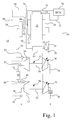
- FIG. 1 there is shown an internal combustion engine system 10 having at its heart an air-breathing, fuel-consuming, multicylinder internal combustion engine 12 that receives combustion air from an intake manifold 14 and has a fuel system 16 supplying fuel for combustion which is discharged through exhaust manifold 18.
- Internal combustion engine 12 can be a reciprocating type in which pistons reciprocate within cylinders in an appropriate in-line or V configuration and are connected to a crank shaft so that their up and down motion is converted into a rotary torque output.
- the engine 12 may utilize any one of a number of operating cycles including a spark ignition engine in which fuel is mixed with combustion air prior to entry in the engine cylinders and ignited by an ignition source.
- the engine may be a compression ignition or diesel cycle in which the heat of compression is used to ignite fuel that is directly injected into the individual cylinders for combustion.
- Still another form may be what is referred to as homogenous charge compression ignition engines in which fuel is mixed with the combustion air prior to entry to the cylinder and various parameter controls or devices are used to initiate combustion. With any one of these systems, the products of combustion contain oxides of nitrogen, CO 2 , and other exhaust components.
- the products of combustion are passed through an exhaust conduit 24 leading to a turbine 30 of a high pressure turbocharger 32.
- the gasses discharged from turbine 30 pass through line 34 to turbine 36 of a low pressure turbocharger 38.
- the gasses then pass from turbine 36 via line 40 to ambient A.
- An exhaust after treatment device 22 which typically includes an oxidization catalyst and a particulate filter may be positioned in line 40 as shown or may be located at any point in the exhaust flow path from the engine to ambient A. It should be apparent to those skilled in the art that some form of sound suppression may also be provided in line 40.
- the internal combustion engine system 10 may be employed with or without one or both of the turbochargers 32 and 38 in accordance with the present invention.
- one or both of the turbocharger turbines 30 and 36 may employ variable geometry, as illustrated by the diagonal arrows, which controls air flow and the EGR fraction.
- the low pressure turbocharger 38 has a central shaft 42 connected to drive a compressor 44 which receives fresh air from ambient A via intake line 46.
- the air thus pressurized by compressor 44 passes through line 48 through an intercooler 50 to line 52.
- Line 52 provides an inlet for air to compressor 54 of high pressure turbocharger 32 which is driven by turbine 30 through shaft 56.
- the output from compressor 54 passes through line 56, an aftercooler 58 and finally through line 60 to intake manifold 14. It should be noted by those skilled in the art that the intercooler 50 and aftercooler 58 may be incorporated or not incorporated depending upon the particular application for the engine system 10.
- the engine system 10 of Fig. 1 incorporates EGR and to that end a line 62 has a T connection with line 24.
- An EGR valve 26 is positioned within line 62 which extends through a cooler 64 and line 66 to connect with line 60 extending to intake manifold 14.
- EGR valve 26 may take a number of forms but has the functional capability of allowing more or less products of combustion from line 24 to be passed through line 62, cooler 64, and line 66 to the intake 14 of IC engine 12.
- the EGR valve 26 is actuated by control signals from a line 68 leading to an ECM 70 which may also provide control of the fuel system 16 via signal line 72.
- the ECM 70 is programmed to control the valve 26 and variable geometry turbines to produce one of several control algorithms.
- the first group includes an O 2 (mole/mass) fraction, EGR fraction and diluent to air ratio which are measures of EGR
- the second group includes Lambda, Phi and exhaust O 2 (mole/mass fraction) which are measures of fresh air to fuel ratio.
- a typical control scheme would control to one of the EGR measures and one of the fresh air to fuel ratio measures. This can be done by controlling the EGR valve 26 and the variable geometry turbines 30 and/or 36. For all of these control logics, it is necessary to provide a measurement of the EGR flow through line 66. Heretofore, this measurement has been taken directly in line 66 or 62 with the attendant deficiencies described above.
- the internal combustion engine system 10 incorporates the following novel EGR measurement.
- the total flow of gasses to engine 12 is calculated using the temperature and pressure at the intake manifold 14, measured by a sensor 74 and providing a signal to ECM 70 via line 76.
- This measurement provides an accurate and responsive measurement of the total flow of gasses consumed by engine 12.
- the fresh air flow is measured by any one of a number of flow sensors 78, 82, 84, and 86.
- the signal from any one of these locations is fed by lines indicated by dashed lines 88 to a signal line 90 extending to ECM 70.
- the flow sensors 78-86 may either be a venturi or orifice in which pressure, temperature, and differential pressure are used to calculate the air flow past a sensor.
- the signal from any one of the sensors 78-86 is fed to the ECM 70 which is configured to subtract the fresh air flow, as sensed by these flow sensors, from the total air flow as calculated by the ECM 70 to provide a signal representing the actual flow of gasses through the EGR lines 62 and 66.
- the sensors are in the fresh air line, they are not subject to the adverse impact of pulsating flow when measuring in the EGR passages. This results in a signal that is significantly more stable and accurate than the prior methods of measuring flow actually in the EGR passages. It should be noted that any one of the locations for the sensors 78-86 may be selected depending upon the delta P ranges at that point and local velocity variations. The resultant system offers a significant increase in reliability and effectiveness. In addition, using the restriction in the fresh air line does not have the adverse impact on pumping losses that are found when measuring directly in the EGR loop.
Landscapes
- Engineering & Computer Science (AREA)
- Chemical & Material Sciences (AREA)
- Combustion & Propulsion (AREA)
- Mechanical Engineering (AREA)
- General Engineering & Computer Science (AREA)
- Exhaust-Gas Circulating Devices (AREA)
Applications Claiming Priority (1)
| Application Number | Priority Date | Filing Date | Title |
|---|---|---|---|
| US12/330,565 US7937208B2 (en) | 2008-12-09 | 2008-12-09 | Apparatus for measuring EGR and method |
Publications (1)
| Publication Number | Publication Date |
|---|---|
| EP2199577A1 true EP2199577A1 (fr) | 2010-06-23 |
Family
ID=41728089
Family Applications (1)
| Application Number | Title | Priority Date | Filing Date |
|---|---|---|---|
| EP09177183A Withdrawn EP2199577A1 (fr) | 2008-12-09 | 2009-11-26 | Estimation du débit massique d'air dans le circuit de recirculation des gaz d'échappement |
Country Status (4)
| Country | Link |
|---|---|
| US (1) | US7937208B2 (fr) |
| EP (1) | EP2199577A1 (fr) |
| CN (1) | CN101749146A (fr) |
| BR (1) | BRPI0904987A2 (fr) |
Cited By (1)
| Publication number | Priority date | Publication date | Assignee | Title |
|---|---|---|---|---|
| CN103016214A (zh) * | 2012-12-11 | 2013-04-03 | 山东绿环动力设备有限公司 | 柴油机废气再循环系统 |
Families Citing this family (7)
| Publication number | Priority date | Publication date | Assignee | Title |
|---|---|---|---|---|
| DE102010029385A1 (de) * | 2010-05-27 | 2011-12-01 | Robert Bosch Gmbh | Laserinduzierte Fremdzündung für eine Brennkraftmaschine |
| JP2012197716A (ja) * | 2011-03-22 | 2012-10-18 | Hino Motors Ltd | 排気損失回収装置 |
| US9068502B2 (en) * | 2011-09-13 | 2015-06-30 | Caterpillar Inc. | EGR flow measurement |
| US9279406B2 (en) | 2012-06-22 | 2016-03-08 | Illinois Tool Works, Inc. | System and method for analyzing carbon build up in an engine |
| FR3009020B1 (fr) * | 2013-07-26 | 2017-11-03 | Valeo Systemes De Controle Moteur | Procede et dispositif pour la determination de la concentration des gaz d'echappement recirculant a l'entree du repartiteur d'admission d'un moteur thermique |
| CN105673266B (zh) * | 2016-01-14 | 2018-05-04 | 潍柴动力股份有限公司 | 一种egr发动机的egr废气流量测量方法 |
| CN106640344B (zh) * | 2016-12-29 | 2018-12-14 | 潍柴动力股份有限公司 | 用于计算发动机的进气温度、中冷器效率的方法及发动机 |
Citations (4)
| Publication number | Priority date | Publication date | Assignee | Title |
|---|---|---|---|---|
| US20020179060A1 (en) | 2000-04-06 | 2002-12-05 | Gerhard Engel | Method and device for controlling an internal combustion engine |
| US20040084015A1 (en) * | 2002-11-05 | 2004-05-06 | Jing Sun | System and method for estimating and controlling cylinder air charge in a direct injection internal combustion engine |
| FR2910929A1 (fr) * | 2006-12-27 | 2008-07-04 | Renault Sas | Procede et systeme d'estimation et de regulation du debit d'air frais alimentant un moteur a combustion interne suralimente par un turbocompresseur. |
| EP2098710A1 (fr) * | 2008-03-04 | 2009-09-09 | GM Global Technology Operations, Inc. | Procédé pour estimer la concentration en oxygène dans des moteurs à combustion interne |
Family Cites Families (16)
| Publication number | Priority date | Publication date | Assignee | Title |
|---|---|---|---|---|
| US5918582A (en) | 1995-07-13 | 1999-07-06 | Nissan Motor | Integrated internal combustion engine control system with high-precision emission controls |
| JP3144327B2 (ja) | 1996-12-19 | 2001-03-12 | トヨタ自動車株式会社 | 内燃機関の燃料噴射量制御装置 |
| US6944532B2 (en) * | 1998-06-18 | 2005-09-13 | Cummins, Inc. | System for controlling an internal combustion engine in a fuel efficient manner |
| DE19964362B4 (de) * | 1999-03-19 | 2010-06-17 | Daimler Ag | Verfahren zur Regelung des Anteils der einer Brennkraftmaschine rückgeführten Abgasmenge |
| US6408834B1 (en) * | 2001-01-31 | 2002-06-25 | Cummins, Inc. | System for decoupling EGR flow and turbocharger swallowing capacity/efficiency control mechanisms |
| US6866610B2 (en) | 2001-03-30 | 2005-03-15 | Toyota Jidosha Kabushiki Kaisha | Control apparatus and method for vehicle having internal combustion engine and continuously variable transmission, and control apparatus and method for internal combustion engine |
| DE10254477B3 (de) | 2002-11-21 | 2004-06-24 | Siemens Ag | Prüfverfahren für einen Abgaskatalysator und eine entsprechende Prüfeinrichtung |
| JP2004197615A (ja) * | 2002-12-17 | 2004-07-15 | Toyota Motor Corp | 内燃機関の新気量算出装置 |
| US6922987B2 (en) | 2003-02-12 | 2005-08-02 | Fleetguard, Inc. | System and method for enhancing internal combustion engine aftertreatment applications by superheated fuel injection |
| US7140357B2 (en) | 2004-09-21 | 2006-11-28 | International Engine Intellectual Property Company, Llc | Vortex mixing system for exhaust gas recirculation (EGR) |
| US7028680B2 (en) | 2004-09-21 | 2006-04-18 | International Engine Intellectual Property Company, Llc | Two stage mixing system for exhaust gas recirculation (EGR) |
| US7032578B2 (en) | 2004-09-21 | 2006-04-25 | International Engine Intellectual Property Company, Llc | Venturi mixing system for exhaust gas recirculation (EGR) |
| DE102004061453A1 (de) * | 2004-12-17 | 2006-06-29 | Delphi Technologies, Inc., Troy | Verfahren und Vorrichtung zur Motorsteuerung bei einem Kraftfahrzeug |
| JP2006220098A (ja) | 2005-02-14 | 2006-08-24 | Hitachi Ltd | センサ若しくは電磁気的作動要素及び燃料噴射弁及びその制御方法又は駆動方法 |
| US20070056266A1 (en) | 2005-09-13 | 2007-03-15 | Eric Kurtz | System and method for regenerating a NOx storage and conversion device |
| JP4380754B2 (ja) * | 2007-09-21 | 2009-12-09 | トヨタ自動車株式会社 | 内燃機関の排気還流装置 |
-
2008
- 2008-12-09 US US12/330,565 patent/US7937208B2/en active Active
-
2009
- 2009-11-10 CN CN200910210570A patent/CN101749146A/zh active Pending
- 2009-11-26 EP EP09177183A patent/EP2199577A1/fr not_active Withdrawn
- 2009-12-07 BR BRPI0904987-8A patent/BRPI0904987A2/pt not_active IP Right Cessation
Patent Citations (4)
| Publication number | Priority date | Publication date | Assignee | Title |
|---|---|---|---|---|
| US20020179060A1 (en) | 2000-04-06 | 2002-12-05 | Gerhard Engel | Method and device for controlling an internal combustion engine |
| US20040084015A1 (en) * | 2002-11-05 | 2004-05-06 | Jing Sun | System and method for estimating and controlling cylinder air charge in a direct injection internal combustion engine |
| FR2910929A1 (fr) * | 2006-12-27 | 2008-07-04 | Renault Sas | Procede et systeme d'estimation et de regulation du debit d'air frais alimentant un moteur a combustion interne suralimente par un turbocompresseur. |
| EP2098710A1 (fr) * | 2008-03-04 | 2009-09-09 | GM Global Technology Operations, Inc. | Procédé pour estimer la concentration en oxygène dans des moteurs à combustion interne |
Cited By (1)
| Publication number | Priority date | Publication date | Assignee | Title |
|---|---|---|---|---|
| CN103016214A (zh) * | 2012-12-11 | 2013-04-03 | 山东绿环动力设备有限公司 | 柴油机废气再循环系统 |
Also Published As
| Publication number | Publication date |
|---|---|
| US7937208B2 (en) | 2011-05-03 |
| US20100145598A1 (en) | 2010-06-10 |
| CN101749146A (zh) | 2010-06-23 |
| BRPI0904987A2 (pt) | 2011-02-08 |
Similar Documents
| Publication | Publication Date | Title |
|---|---|---|
| US7937208B2 (en) | Apparatus for measuring EGR and method | |
| JP4935933B2 (ja) | 内燃機関の制御装置、及びブローバイガスとともに吸気通路に還流されるNOxの質量流量の計測装置 | |
| JP4417289B2 (ja) | 内燃機関内により取り込まれた気体混合物中の酸素濃度の測定に基づいて、内燃機関での排ガス再循環を制御する方法および装置 | |
| US6945236B2 (en) | EGR control apparatus for engine | |
| CN100467842C (zh) | 内燃机控制设备 | |
| US6820600B1 (en) | Method for controlling an engine with an EGR system | |
| CN100360780C (zh) | 用于内燃机的egr控制装置和方法 | |
| US8112984B2 (en) | Method and device for the diagnosis of the effectiveness of a catalytic converter | |
| EP1790840A1 (fr) | Dispositif de commande de moteur a combustion interne | |
| US9482147B2 (en) | Method and apparatus to operate internal combustion engine employing an intake air compressor | |
| US7788020B2 (en) | System and method for detecting cylinder misfire | |
| CN101248263B (zh) | 用于控制先导喷射的系统和方法 | |
| WO2008014049A1 (fr) | Système et procédé permettant d'exploiter un moteur à turbocompresseur | |
| EP1519027A2 (fr) | Systeme et méthode pour la commande d'émission de gaz d'échappement | |
| US20170058820A1 (en) | Engine apparatus | |
| US7769526B2 (en) | Diesel transient combustion control based on intake carbon dioxide concentration | |
| JP5929823B2 (ja) | 内燃機関の制御装置 | |
| CN107152346B (zh) | 用于减少颗粒物质的发动机控制系统 | |
| EP1741890A2 (fr) | Dispositif de nettoyage des gaz d'échappement pour un moteur à combustion interne | |
| JP2005009437A (ja) | 多気筒内燃機関の制御装置 | |
| US12092043B2 (en) | Control device of internal combustion engine, and internal combustion engine | |
| US11215137B1 (en) | Engine device | |
| GB2463055A (en) | A method of controlling fuel injection timing in a turbo charged ic engine as a result of acceleration | |
| JP2004353476A (ja) | 内燃機関の制御装置 |
Legal Events
| Date | Code | Title | Description |
|---|---|---|---|
| PUAI | Public reference made under article 153(3) epc to a published international application that has entered the european phase |
Free format text: ORIGINAL CODE: 0009012 |
|
| AK | Designated contracting states |
Kind code of ref document: A1 Designated state(s): AT BE BG CH CY CZ DE DK EE ES FI FR GB GR HR HU IE IS IT LI LT LU LV MC MK MT NL NO PL PT RO SE SI SK SM TR |
|
| AX | Request for extension of the european patent |
Extension state: AL BA RS |
|
| 17P | Request for examination filed |
Effective date: 20101223 |
|
| 17Q | First examination report despatched |
Effective date: 20110204 |
|
| STAA | Information on the status of an ep patent application or granted ep patent |
Free format text: STATUS: THE APPLICATION IS DEEMED TO BE WITHDRAWN |
|
| 18D | Application deemed to be withdrawn |
Effective date: 20120627 |