EP2199620B1 - Axialstromventilator - Google Patents
Axialstromventilator Download PDFInfo
- Publication number
- EP2199620B1 EP2199620B1 EP09180201.7A EP09180201A EP2199620B1 EP 2199620 B1 EP2199620 B1 EP 2199620B1 EP 09180201 A EP09180201 A EP 09180201A EP 2199620 B1 EP2199620 B1 EP 2199620B1
- Authority
- EP
- European Patent Office
- Prior art keywords
- blade
- curved
- curved portion
- axial flow
- flow fan
- Prior art date
- Legal status (The legal status is an assumption and is not a legal conclusion. Google has not performed a legal analysis and makes no representation as to the accuracy of the status listed.)
- Active
Links
Images


Classifications
-
- F—MECHANICAL ENGINEERING; LIGHTING; HEATING; WEAPONS; BLASTING
- F04—POSITIVE - DISPLACEMENT MACHINES FOR LIQUIDS; PUMPS FOR LIQUIDS OR ELASTIC FLUIDS
- F04D—NON-POSITIVE-DISPLACEMENT PUMPS
- F04D29/00—Details, component parts, or accessories
- F04D29/26—Rotors specially for elastic fluids
- F04D29/32—Rotors specially for elastic fluids for axial flow pumps
- F04D29/38—Blades
- F04D29/384—Blades characterised by form
-
- F—MECHANICAL ENGINEERING; LIGHTING; HEATING; WEAPONS; BLASTING
- F04—POSITIVE - DISPLACEMENT MACHINES FOR LIQUIDS; PUMPS FOR LIQUIDS OR ELASTIC FLUIDS
- F04D—NON-POSITIVE-DISPLACEMENT PUMPS
- F04D25/00—Pumping installations or systems
- F04D25/02—Units comprising pumps and their driving means
- F04D25/06—Units comprising pumps and their driving means the pump being electrically driven
- F04D25/0606—Units comprising pumps and their driving means the pump being electrically driven the electric motor being specially adapted for integration in the pump
- F04D25/0613—Units comprising pumps and their driving means the pump being electrically driven the electric motor being specially adapted for integration in the pump the electric motor being of the inside-out type, i.e. the rotor is arranged radially outside a central stator
-
- F—MECHANICAL ENGINEERING; LIGHTING; HEATING; WEAPONS; BLASTING
- F05—INDEXING SCHEMES RELATING TO ENGINES OR PUMPS IN VARIOUS SUBCLASSES OF CLASSES F01-F04
- F05D—INDEXING SCHEME FOR ASPECTS RELATING TO NON-POSITIVE-DISPLACEMENT MACHINES OR ENGINES, GAS-TURBINES OR JET-PROPULSION PLANTS
- F05D2240/00—Components
- F05D2240/20—Rotors
- F05D2240/30—Characteristics of rotor blades, i.e. of any element transforming dynamic fluid energy to or from rotational energy and being attached to a rotor
- F05D2240/307—Characteristics of rotor blades, i.e. of any element transforming dynamic fluid energy to or from rotational energy and being attached to a rotor related to the tip of a rotor blade
Definitions
- the present invention relates to an axial flow fan.
- Japanese Utility Model Registration No. 3089140 discloses in FIGs. 1 to 3 an impeller of an axial flow fan in which a projecting edge 322 curved to form an included angle ⁇ on the upper surface of a blade 32 is formed at a radially outer end portion thereof.
- Japanese Utility Model Registration No. 3089140 U.S. Patent Application Publication No. 2003/0123988 . describes that vortices 23 are generated at the radially end portion 13 of the blade as shown in FIG. 5 of the publication if the projecting edge 322 is not formed. Further, the publication describes that the vortex 23 leads to a reduction of static pressure, reduction of air volume, and increase of noise. Furthermore, the publication describes that the formation of the projecting edge 322 allows the static pressure to be increased, air volume to be increased, and noise to be reduced, as compared to when the projection edge 322 is not formed. The inventor of the present invention has confirmed that the effects described in the publication may be obtained.
- JP2000 192898A (Sharp kk) and JPH08 177792A (Matsushita Seiko kk) each describe a fan having the precharacterizing features of claim 1.
- An object of the present invention is to provide an axial flow fan in which an amount of dropping at the inflection point appearing in air volume - static pressure characteristics may be reduced and noise may also be reduced as compared to conventional axial flow fans.
- an axial flow fan having the characterizing features of claim 1.
- one outer surface portion positioned on one side of the curved portion exist on an extended surface of the other outer surface portion.
- an outline of the rear end edge of the blade be curved to be convex in the rotation direction at a position corresponding to the curved portion.
- the deepest point of the concave portion be positioned within a range from 0.8R to 0.95R.
- the deepest point of the concave portion exists at a position closer to the base portion relative to the radial position corresponding to 0.8R, the inflection point of the air volume - static pressure characteristics decreases.
- the length L of the curved portion as measured in the circumferential direction of the peripheral wall portion of the hub be in a range from 2 ⁇ R/(2.8N) to 2 ⁇ R/(1.5N). If the length L of the curved portion as measured in the circumferential direction is less than 2 ⁇ R/(2.8N), the air volume is reduced to cause an increase in the amount of dropping at the inflection point of the air volume - static pressure characteristics. If the length L of the curved portion as measured in the circumferential direction is more than 2 ⁇ R/(1.5N), the inflection point of the air volume - static pressure characteristics decreases as a whole, leading to an increase of noise.
- the maximum value for the width of the curved portion be in a range from 0.15R to 0.20R. If the maximum value for the width of the curved portion is less than 0.15R, the air volume is reduced to cause an increase in the amount of dropping at the inflection point of the air volume - static pressure characteristics, leading to an increase of noise. If the maximum value for the width of the curved portion is more than 0.20R, the inflection point of the air volume - static pressure characteristics decreases, leading to an increase of noise.
- the maximum value for the depth D of the concave portion of the curved portion be in a range from 0.02R to 0.05R. If the maximum value for the depth D of the concave portion of the curved portion is less than 0.02R, the amount of dropping at the inflection point of the air volume - static pressure characteristics is increased to increase noise. If the maximum value for the depth D of the concave portion of the curved portion is more than 0.05R, the inflection point of the air volume - static pressure characteristics significantly decreases to increase noise. Specifically, the maximum value for the depth D of the curved portion may preferably be 1 to 2 mm.
- the present invention it is possible to reduce the amount of dropping at the inflection point appearing in air volume - static pressure characteristics than in a conventional axial flow fan in which a projecting edge is formed over the entire length of the radially outer end portion of the blade, which further leads to a reduction in noise.
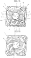
- FIGs. 1A and 1B are respectively a front-side perspective view and a rear-side perspective view of an axial flow fan 1 according to an embodiment of the present invention.
- the axial flow fan 1 includes a housing 3, an impeller 7 having seven blades 5 which are disposed in the housing 3 and rotating therein, and a motor 9 which drives and rotates the impeller 7.
- the motor 9 includes a rotary shaft 8, as indicated with a dot line, having a front end portion and a rear end portion.
- the impeller 7 is fixed to the front end portion of the rotary shaft 8.
- a motor case 10 is fixed to the housing 3 through webs 11.
- the housing 3 has a suction-side flange 13 of an annular shape at one side in an extending direction of the axial line (axial direction) of the rotary shaft 8 and a discharge-side flange 15 of an annular shape at the other side in the extending direction of the axial line.
- the housing 3 also includes a cylindrical portion 17 between the flanges 13 and 15.
- An air channel 19 is formed by internal spaces of the suction-side flange 13, the discharge-side flange 15, and the cylindrical portion 17.
- the impeller 7 is rotated in the air channel 19.
- the impeller 7 includes a hub 6 having an annular peripheral wall portion 6A and seven blades 5.
- a plurality of permanent magnets constituting a part of a rotor of the motor 9 are fixed to the inside of the peripheral wall portion 6A of the hub 6.
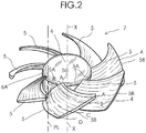
- FIG. 2 is an enlarged perspective view of the impeller 7 used in the present embodiment.
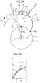
- FIG. 3A is a plan view showing that one blade 5 is mounted onto the hub 6, and
- FIG. 3B is a schematic view explaining that a base portion 5A of one blade 5 is mounted onto the peripheral wall portion 6A of the hub 6.
- FIGs. 4A to 4D are cross-sectional views respectively taken along lines A-A, B-B, C-C, and D-D of FIG. 2 .
- the seven blades 5 are integrally fixed to an outer wall of the peripheral wall portion 6A of the hub 6 at their base portions 5A.
- the seven blades 5 extend outwardly in a radial direction of the peripheral wall portion 6A from the outer wall of the peripheral wall portion 6A of the hub 6 and are disposed at an interval in a circumferential direction of the peripheral wall portion 6A.
- Each blade 5 has the following features.
- an imaginary line PL is assumed to pass one end 5Aa of the base portion 5A of the blade 5 positioned on the rear end side of the rotary shaft 8 and extending in parallel to the axial line X of the rotary shaft 8 along the outer peripheral surface of the peripheral wall portion 6A.
- the base portion 5A of the blade 5 is inclined in a direction from one end 5Aa of the base portion 5A to the other end 5Ab of the base portion 5A so as to be gradually away from the imaginary line PL in the rotation direction RD of the impeller 7, and curved so as to be convex in a direction opposite to the rotation direction RD.
- the blades 5 are fixed to the hub 6 in such a manner that the blades 5 are inclined along the peripheral wall portion 6A of the hub 6 such that the one end 5Aa of the base portion 5A is positioned in the vicinity of an opening portion of the peripheral wall portion 6A of the hub 6 as shown in FIG. 4D and the other end 5Ab of the base portion 5A is positioned more forward in the rotation direction RD than the one end 5Aa and is positioned opposite to the opening portion of the peripheral wall portion 6A as shown in FIG. 3 and FIG. 4A .
- Each blade 5 used in the present embodiment has a curved portion 4 as shown in FIGs. 4B to 4D .
- the curved portion 4 is formed in the vicinity of a radially outer end portion 5B positioned opposite to the base portion 5A in the radial direction of the peripheral wall portion 6A of the hub 6.
- the curved portion 4 is convex in the rotation direction RD, and is concave in the direction opposite to the rotation direction RD, and extends along the radially outer end portion 5B of the blade 5. More specifically, as shown in FIG.
- the curved portion 4 extends along the radially outer end portion 5B from a rear end edge 5C of the blade 5 positioned on a side where the one end 5Aa of the base portion 5A of the blade 5 is positioned and extending in the radial direction of the hub 6 to the vicinity of a front end edge 5D of the blade 5 positioned on a side where the other end 5Ab of the base portion 5A of the blade 5 is positioned and extending in the radial direction of the hub 6.
- the shape of the blade 5 is defined such that outer surface portions 5Ea and 5Eb positioned on both sides of the curved portion 4 in the radial direction exist in the same curved surface, in other words, the outer surface portion 5Eb exists on an extended surface of the outer surface portion 5Ea as viewed from the rear end edge 5C side.
- an outline of the rear end edge 5C of the blade 5 is curved to be convex in the rotation direction RD at a position corresponding to the curved portion 4.
- a dotted line 5C' in FIG. 3A denotes the outline of the rear end edge 5C when the curved portion 4 is not formed.
- the outline of the rear end edge 5C of the blade 5 is curved in an elongated S-shape.
- the width W of the curved portion 4 and the depth D of a concave portion 4A formed in the curved portion 4 as measured in the radial direction are determined so as to gradually decrease from the rear end edge 5C toward the front end edge 5D.
- the curved portion 4 be formed such that the deepest point of the concave portion 4A is positioned within a range from 0.8R to 0.95R.
- the locus of the deepest point of the concave portion 4A is denoted by a dotted line T.
- the maximum value for the width W of the curved portion 4 be in a range from 0.15R to 0.20R. If the maximum value for the width W of the curved portion 4 is less than 0.15R, the air volume is reduced to cause an increase in the amount of dropping at the inflection point of the air volume - static pressure characteristics as a whole, leading to an increase of noise. If the maximum value for the width W of the curved portion 4 is more than 0.20R, the inflection point of the air volume-static pressure characteristics decreases as a whole, leading to an increase of noise. Further, it is preferable that the maximum value for the depth D of the concave portion 4A of the curved portion 4 be in a range from 0.02R to 0.05R.
- the maximum value for the depth D of the concave portion 4A of the curved portion 4 is less than 0.02R, the air volume is reduced to cause an increase in the amount of dropping at the inflection point of the air volume - static pressure characteristics, leading to an increase of noise. If the maximum value for the depth D of the concave portion 4A of the curved portion 4 is more than 0.05R, the inflection point of the air volume - static pressure characteristics decreases as a whole, leading to an increase of noise.
- the length L of the curved portion 4 as measured in the circumferential direction of the peripheral wall portion 6A of the hub 6 be in a range from 2 ⁇ R/(2.8N) to 2 ⁇ R/(1.5N). If the length L of the curved portion 4 as measured in the circumferential direction is less than 2 ⁇ R/(2.8N), the air volume is reduced to cause an increase in the amount of dropping at the inflection point of the air volume-static pressure characteristics, leading to an increase of noise. If the length L of the curved portion 4 as measured in the circumferential direction is more than 2 ⁇ R/(1.5N), the inflection point of the air volume - static pressure characteristics decreases, leading to an increase of noise.
- FIG. 5 is a perspective view of an impeller used in an axial flow fan according to a first comparative example
- FIGS. 6A and 6B are cross-sectional views respectively taken along lines A-A and B-B of FIG. 5 .
- the impeller of the axial flow fan according to the first comparative example has a configuration in which a curved portion 4' is formed over the entire length of a blade 5', from a rear end edge 5'C of the blade 5' to front end edge 5'D thereof.
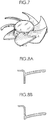
- FIG. 7 is a perspective view of an impeller used in an axial flow fan according to a second comparative example
- FIGS. 8A and 8B are cross-sectional views respectively taken along lines A-A and B-B of FIG. 7 .
- the impeller of the axial flow fan according to the comparative example 2 does not have the curved portion.
- the radius R of the impellers of the axial flow fans used in the test was 43 mm, and rotation speed thereof was 4,400 [min -1 ].
- the deepest point of the concave portion 4A of the curved portion 4 was set at a position of 0.9R assuming that the outer diameter of the impeller 7 is R.
- the length L of the curved portion 4 was set to 2 ⁇ R/(1.5N)
- the width W of the curved portion 4 was set to 0.19R
- the maximum value for the depth D of the concave portion 4A was set to 0.03R.
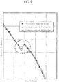
- FIG. 9 shows the air volume - static pressure characteristics of the axial flow fans according to the present embodiment and the first and second comparative examples under the above conditions.
- a region surrounded by a dotted line in FIG. 9 is the operating range in which the inflection point appears.
- the inflection point point at which the polarity of a variation of characteristics changes
- the amount of dropping (decrease in the characteristics) at the inflection point in the axial flow fan according to the present embodiment is smaller than that in any of the axial flow fans according to the first and second comparative examples.
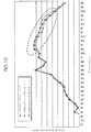
- FIG. 10 shows a relationship between the sound pressure level and frequency component in the axial flow fans according to the present embodiment and the first and second comparative examples measured under the same environment.
- the noise in the fan is mainly constituted by so-called turbulence noise. This noise is caused by a comparatively high frequency component (range surrounded by a dotted line in FIG. 10 : 1.2 kHz to 16 kHz).
- the sound pressure level of a frequency component which is a generation source of the noise is reduced in the axial flow fan according to the present embodiment as compared to that in any of the axial flow fans according to the first and second comparative examples.
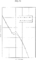
- FIG. 11 shows average air volume - static pressure characteristics when the deepest point of the concave portion 4A of the curved portion 4 exists in a proper range from 0.8R to 0.95R and the deepest point of the concave portion 4A exists at a position corresponding to less than 0.8R, assuming that the outer diameter of the impeller 7 is R. If the deepest point of the concave portion 4A exists at a position corresponding to more than 0.95R, the characteristics change in the same manner as with when the deepest point of the concave portion 4A exists at a position corresponding to less than 0.8R, In FIG.
- the length L of the curved portion 4 was set to 2 ⁇ R/(1,5N), the width W of the curved portion 4 was set to 0.19R, and the maximum value for the depth D of the concave portion 4A was set to 0.03R.
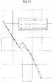
- FIG. 12 is a graph showing, together with the above-mentioned air volume - static pressure characteristics of the present embodiment, air volume - static pressure characteristics obtained when the position of the curved portion 4 was set to a position corresponding to 0.9R, the length of the curved portion 4 was set to 2 ⁇ R/(1.4N), the width W of the curved portion 4 was set to 0.21R, and the maximum value for the depth D of the concave portion 4A was set to 0.051R was defined as "curved portion - large" and when the position of the curved portion 4 was set to a position corresponding to 0.9R, the length of the curved portion 4 was set to 2nR/(2.9N), the width W of the curved portion 4 was set to 0.14R, and the maximum value for the depth D of the concave portion 4A was set to 0.019R was defined as "curved portion - small”.
Landscapes
- Engineering & Computer Science (AREA)
- Mechanical Engineering (AREA)
- General Engineering & Computer Science (AREA)
- Structures Of Non-Positive Displacement Pumps (AREA)
Claims (7)
- Axialstromventilator (1), umfassend:einen Impeller (7) mit einer Nabe (6), die einen ringförmigen, peripheren Wandabschnitt (6A) aufweist, und einer Vielzahl von Schaufeln (5), die jeweils einen Basisabschnitt (5A), der einteilig an einer äußeren Wand des peripheren Wandabschnitts (6A) der Nabe (6) fixiert ist, aufweisen, sich von der äußeren Wand des peripheren Wandabschnitts (6A) nach außen in einer Radialrichtung des peripheren Wandabschnitts (6A) erstrecken, und in einem Intervall in einer Umfangsrichtung des peripheren Wandabschnitts (6A) angeordnet sind;ein Gehäuse (3), das einen zylindrischen Luftkanal (19) aufweist, in welchem sich der Impeller (7) dreht; undeinen Motor (9), der an dem Gehäuse (3) fixiert ist und eine drehbare Welle (8) mit einem vorderen Endabschnitt, an welchem der Impeller (7) fixiert ist, und einem hinteren Endabschnitt umfasst, wobei:unter Annahme einer gedachten Linie (PL), die ein Ende (5Aa) des Basisabschnittes (5A) der Schaufel (5) passiert, das an der Seite des hinteren Endabschnitts der drehbaren Welle (8) positioniert ist, und sich parallel zu einer axialen Linie (X) der drehbaren Welle (8) und entlang einer äußeren peripheren Oberfläche des peripheren Wandabschnitts (6A) erstreckt, der Basisabschnitt (5A) der Schaufel (5) in eine Richtung von dem einen Ende (5Aa) des Basisabschnitts (5A) zu dem anderen Ende (5Ab) davon geneigt ist, so dass er sich allmählich von der gedachten Linie (PL) in einer Drehrichtung (RD) des Impellers (7) entfernt, und so gekrümmt ist, dass er in einer Richtung, die der Drehrichtung (RD) entgegengesetzt ist, konvex ist;jede Schaufel (5) einen gekrümmten Abschnitt (4) aufweist, der in der Umgebung eines radial äußeren Endabschnitts (5B), der dem Basisabschnitt (5A) in der Radialrichtung entgegengesetzt positioniert ist, ausgebildet ist, wobei der gekrümmte Abschnitt (4) in der Drehrichtung (RD) konvex ist, und in der der Drehrichtung (RD) entgegengesetzten Richtung konkav ist;der gekrümmte Abschnitt (4) sich entlang des radial äußeren Endabschnitts (5B) von einer hinteren Endkante (5C) der Schaufel (5) in die Umgebung einer vorderen Endkante (5D) der Schaufel (5) erstreckt, wobei die hintere Endkante (5C) an einer Seite positioniert ist, wo das eine Ende (5Aa) des Basisabschnitts (5A) positioniert ist und sich in der Radialrichtung erstreckt, wobei die vordere Endkante (5D) der Schaufel (5) an einer Seite positioniert ist, wo das andere Ende (5Ab) des Basisabschnitts (5A) positioniert ist, und sich in der Radialrichtung erstreckt;die Breite des gekrümmten Abschnitts (4), gemessen in der Radialrichtung, und die Tiefe eines konkaven Abschnitts (4A), der in dem gekrümmten Abschnitt (4) ausgebildet ist, so bestimmt sind, dass sie in einer Richtung von der hinteren Endkante (5C) zu der vorderen Endkante (5D) der Schaufel (5) hin allmählich abnehmen, dadurch gekennzeichnet, dass:jede Schaufel einen ersten äußeren Oberflächenabschnitt (5Eb) und einen zweiten äußeren Oberflächenabschnitt (5Ea) aufweist, die an beiden Seiten des gekrümmten Abschnitts (4) in der Radialrichtung positioniert sind, so dass der erste äußere Oberflächenabschnitt (5Eb) radial außerhalb des gekrümmten Abschnitts (4) liegt und der zweite äußere Oberflächenabschnitt (5Ea) radial innerhalb des gekrümmten Abschnitts (4) liegt; unddie ersten und zweiten äußeren Oberflächenabschnitte (5Eb, 5Ea) auf derselben gekrümmten Oberfläche liegen, die in der der Drehrichtung (RD) entgegengesetzten Richtung konvex ist, so dass der erste äußere Oberflächenabschnitt (5Eb), von der Seite der hinteren Endkante (5C) der Schaufel (5) gesehen, auf einer Verlängerung des zweiten äußeren Oberflächenabschnitts (5Ea) vorliegt.
- Axialstromventilator (1) nach Anspruch 1, wobei
ein Umriss der hinteren Endkante (5C) der Schaufel (5) gekrümmt ist, um in der Drehrichtung (RD) an einer Position entsprechend dem gekrümmten Abschnitt (4) konvex zu sein, wenn man den Impeller (7) von dem vorderen Endabschnitt der drehbaren Welle (8) zu dem hinteren Endabschnitt derselben hin betrachtet. - Axialstromventilator (1) nach Anspruch 1, wobei,
unter der Annahme, dass der äußere Durchmesser des Impellers (7) R ist, der gekrümmte Abschnitt (4) so ausgebildet ist, dass der tiefste Punkt des konkaven Abschnitts (4A) innerhalb eines Bereichs von 0,8 R bis 0,95 R angeordnet ist. - Axialstromventilator (1) nach Anspruch 3, wobei,
unter der Annahme, dass die Anzahl von Schaufeln (5) N ist, die Länge L des gekrümmten Abschnitts (4) gemessen in der Umfangsrichtung in einem Bereich von 2πR/(2,8 N) bis 2πR/(1,5 N) liegt. - Axialstromventilator (1) nach Anspruch 3 oder 4, wobei
der Höchstwert für die Breite des gekrümmten Abschnitts (4) in einem Bereich von 0,15 R bis 0,20 R liegt. - Axialstromventilator (1) nach Anspruch 3 oder 4, wobei
der Höchstwert für die Tiefe D des konkaven Abschnitts (4A) des gekrümmten Abschnitts (4) in einem Bereich von 0,02 R bis 0,05 R liegt. - Axialstromventilator (1) nach Anspruch 3, wobei
der Höchstwert für die Tiefe D des konkaven Abschnitts (4A) 1 mm bis 2 mm beträgt.
Applications Claiming Priority (1)
| Application Number | Priority Date | Filing Date | Title |
|---|---|---|---|
| JP2008326283A JP5210852B2 (ja) | 2008-12-22 | 2008-12-22 | 軸流送風機 |
Publications (3)
| Publication Number | Publication Date |
|---|---|
| EP2199620A2 EP2199620A2 (de) | 2010-06-23 |
| EP2199620A3 EP2199620A3 (de) | 2017-02-22 |
| EP2199620B1 true EP2199620B1 (de) | 2019-01-09 |
Family
ID=41665264
Family Applications (1)
| Application Number | Title | Priority Date | Filing Date |
|---|---|---|---|
| EP09180201.7A Active EP2199620B1 (de) | 2008-12-22 | 2009-12-21 | Axialstromventilator |
Country Status (5)
| Country | Link |
|---|---|
| US (1) | US8770943B2 (de) |
| EP (1) | EP2199620B1 (de) |
| JP (1) | JP5210852B2 (de) |
| CN (1) | CN101761493B (de) |
| TW (1) | TWI484104B (de) |
Families Citing this family (21)
| Publication number | Priority date | Publication date | Assignee | Title |
|---|---|---|---|---|
| JP5147784B2 (ja) * | 2009-06-01 | 2013-02-20 | 三菱電機株式会社 | ファンおよび軸流送風機 |
| US9816521B2 (en) | 2012-04-10 | 2017-11-14 | Sharp Kabushiki Kaisha | Propeller fan, fluid feeder, and molding die |
| WO2013154100A1 (ja) * | 2012-04-10 | 2013-10-17 | シャープ株式会社 | プロペラファン、流体送り装置、扇風機および成形用金型 |
| AU353962S (en) | 2013-08-05 | 2014-02-26 | Mitsubishi Electric Corp | Propeller fan |
| AU353966S (en) | 2013-08-05 | 2014-02-26 | Mitsubishi Electric Corp | Propeller fan |
| JP5705945B1 (ja) * | 2013-10-28 | 2015-04-22 | ミネベア株式会社 | 遠心式ファン |
| USD732655S1 (en) * | 2013-11-21 | 2015-06-23 | Sanyo Denki Co., Ltd. | Fan |
| USD723151S1 (en) * | 2013-12-13 | 2015-02-24 | Cooler Master Co., Ltd. | Fan |
| JP6141247B2 (ja) * | 2014-10-03 | 2017-06-07 | シャープ株式会社 | プロペラファン、流体送り装置および成形用金型 |
| JP5905985B1 (ja) | 2015-08-18 | 2016-04-20 | 山洋電気株式会社 | 軸流送風機及び直列型軸流送風機 |
| CN107923410B (zh) | 2015-09-08 | 2021-12-07 | 三菱电机株式会社 | 螺旋桨式风扇、螺旋桨式风扇装置及空气调节装置用室外机 |
| CN109312758B (zh) * | 2016-06-16 | 2021-01-15 | 三菱电机株式会社 | 轴流送风机 |
| JP6849366B2 (ja) * | 2016-09-29 | 2021-03-24 | 山洋電気株式会社 | リバーシブルフローファン |
| US11519422B2 (en) * | 2018-05-09 | 2022-12-06 | York Guangzhou Air Conditioning And Refrigeration Co., Ltd. | Blade and axial flow impeller using same |
| CN108506247B (zh) * | 2018-05-09 | 2024-08-23 | 约克广州空调冷冻设备有限公司 | 叶片及使用其的轴流叶轮 |
| WO2020077802A1 (zh) * | 2018-10-15 | 2020-04-23 | 广东美的白色家电技术创新中心有限公司 | 对旋风扇 |
| JP7289235B2 (ja) * | 2019-07-18 | 2023-06-09 | 株式会社コロナ | エアコン装置の室外機用プロペラファン |
| JP2024015654A (ja) | 2022-07-25 | 2024-02-06 | 山洋電気株式会社 | 軸流ファン |
| JP2024051594A (ja) * | 2022-09-30 | 2024-04-11 | 山洋電気株式会社 | 軸流ファン |
| CN119103160A (zh) * | 2023-06-07 | 2024-12-10 | 全亿大科技(佛山)有限公司 | 叶轮、散热风扇及电子设备 |
| USD1103130S1 (en) * | 2024-01-08 | 2025-11-25 | Zhijie Chen | Cooling fan |
Family Cites Families (19)
| Publication number | Priority date | Publication date | Assignee | Title |
|---|---|---|---|---|
| JPH0389140A (ja) | 1989-08-31 | 1991-04-15 | Shimadzu Corp | ムーニ試験用試験片の作成方法 |
| US4930990A (en) * | 1989-09-15 | 1990-06-05 | Siemens-Bendix Automotive Electronics Limited | Quiet clutch fan blade |
| DE4020952A1 (de) * | 1990-06-30 | 1992-01-02 | Bosch Gmbh Robert | Geblaese mit einem umlaufenden schaufelrad |
| US5215441A (en) * | 1991-11-07 | 1993-06-01 | Carrier Corporation | Air conditioner with condensate slinging fan |
| JPH08177792A (ja) * | 1994-10-25 | 1996-07-12 | Matsushita Seiko Co Ltd | 軸流ファン |
| JPH1144432A (ja) * | 1997-07-24 | 1999-02-16 | Hitachi Ltd | 空気調和機 |
| JP3524410B2 (ja) * | 1998-12-25 | 2004-05-10 | シャープ株式会社 | プロペラファン |
| JP3960776B2 (ja) * | 2001-11-09 | 2007-08-15 | 松下電器産業株式会社 | 空調用送風機羽根車 |
| TW585227U (en) | 2001-12-31 | 2004-04-21 | Asia Vital Components Co Ltd | Improved structure for fan blade |
| AU2003207098B2 (en) * | 2002-02-28 | 2004-12-23 | Daikin Industries, Ltd. | Fan |
| JP3089140U (ja) | 2002-04-08 | 2002-10-11 | 奇▲こう▼科技股▲ふん▼有限公司 | ファンの羽根 |
| JP2005016457A (ja) * | 2003-06-27 | 2005-01-20 | Matsushita Electric Ind Co Ltd | 送風機及び送風機を備えた熱交換ユニット |
| CN1590778A (zh) * | 2003-08-25 | 2005-03-09 | 乐金电子(天津)电器有限公司 | 轴流风扇 |
| JP4308718B2 (ja) * | 2004-06-15 | 2009-08-05 | 三星電子株式会社 | 遠心ファンおよびこれを用いた空気調和機 |
| JP2006002584A (ja) * | 2004-06-15 | 2006-01-05 | Samsung Electronics Co Ltd | プロペラファンおよびこれを用いた空気調和機 |
| JP4501575B2 (ja) * | 2004-07-26 | 2010-07-14 | 三菱電機株式会社 | 軸流送風機 |
| JP4689262B2 (ja) * | 2004-12-21 | 2011-05-25 | 東芝キヤリア株式会社 | 軸流ファン、空気調和機の室外機 |
| JP2006322378A (ja) * | 2005-05-19 | 2006-11-30 | Matsushita Electric Ind Co Ltd | 送風機羽根車 |
| JP2008051074A (ja) * | 2006-08-28 | 2008-03-06 | Samsung Electronics Co Ltd | プロペラファン |
-
2008
- 2008-12-22 JP JP2008326283A patent/JP5210852B2/ja active Active
-
2009
- 2009-12-21 EP EP09180201.7A patent/EP2199620B1/de active Active
- 2009-12-21 TW TW098143918A patent/TWI484104B/zh active
- 2009-12-22 US US12/644,385 patent/US8770943B2/en active Active
- 2009-12-22 CN CN2009102622770A patent/CN101761493B/zh active Active
Non-Patent Citations (1)
| Title |
|---|
| None * |
Also Published As
| Publication number | Publication date |
|---|---|
| CN101761493A (zh) | 2010-06-30 |
| TW201040398A (en) | 2010-11-16 |
| TWI484104B (zh) | 2015-05-11 |
| EP2199620A2 (de) | 2010-06-23 |
| US20100158677A1 (en) | 2010-06-24 |
| CN101761493B (zh) | 2013-03-27 |
| JP2010144702A (ja) | 2010-07-01 |
| EP2199620A3 (de) | 2017-02-22 |
| JP5210852B2 (ja) | 2013-06-12 |
| US8770943B2 (en) | 2014-07-08 |
Similar Documents
| Publication | Publication Date | Title |
|---|---|---|
| EP2199620A2 (de) | Axialstromventilator | |
| US7762769B2 (en) | Axial fan assembly | |
| US7244099B2 (en) | Multi-vane centrifugal fan | |
| US20190226492A1 (en) | Serrated fan blade, axial fan, and centrifugal fan | |
| US20040136830A1 (en) | Fan | |
| EP3133292A1 (de) | Axialgebläse und axialgebläse vom serientyp | |
| JP3919496B2 (ja) | ラジエータファンおよびこれを用いたエンジン冷却装置 | |
| US20130084173A1 (en) | Centrifugal fan | |
| US20080253897A1 (en) | Axial Flow Fan | |
| JP4099458B2 (ja) | 静翼を含む遠心ファン | |
| KR20030018460A (ko) | 터보팬 | |
| JP5992778B2 (ja) | 軸流ファン | |
| JP2003180051A (ja) | 全閉外扇形回転電機の回転羽根 | |
| JP2006322378A (ja) | 送風機羽根車 | |
| JP2002285996A (ja) | 多翼送風ファン | |
| JPH09287595A (ja) | ファン | |
| JP2006200457A (ja) | 送風機 | |
| KR100255771B1 (ko) | 축류/사류팬 구조 | |
| JP2014043780A (ja) | 直列型軸流ファン | |
| CN102878093B (zh) | 离心式风扇 | |
| CN1273748C (zh) | 贯流风扇 | |
| JP2000110788A (ja) | 軸流ファン | |
| JPH07269494A (ja) | 軸流ファン | |
| JPS61190198A (ja) | 薄形軸流フアン | |
| JP2007100518A (ja) | 軸流ファン |
Legal Events
| Date | Code | Title | Description |
|---|---|---|---|
| PUAI | Public reference made under article 153(3) epc to a published international application that has entered the european phase |
Free format text: ORIGINAL CODE: 0009012 |
|
| AK | Designated contracting states |
Kind code of ref document: A2 Designated state(s): AT BE BG CH CY CZ DE DK EE ES FI FR GB GR HR HU IE IS IT LI LT LU LV MC MK MT NL NO PL PT RO SE SI SK SM TR |
|
| AX | Request for extension of the european patent |
Extension state: AL BA RS |
|
| PUAL | Search report despatched |
Free format text: ORIGINAL CODE: 0009013 |
|
| AK | Designated contracting states |
Kind code of ref document: A3 Designated state(s): AT BE BG CH CY CZ DE DK EE ES FI FR GB GR HR HU IE IS IT LI LT LU LV MC MK MT NL NO PL PT RO SE SI SK SM TR |
|
| AX | Request for extension of the european patent |
Extension state: AL BA RS |
|
| RIC1 | Information provided on ipc code assigned before grant |
Ipc: F04D 29/38 20060101ALI20170118BHEP Ipc: F04D 25/06 20060101AFI20170118BHEP |
|
| STAA | Information on the status of an ep patent application or granted ep patent |
Free format text: STATUS: REQUEST FOR EXAMINATION WAS MADE |
|
| 17P | Request for examination filed |
Effective date: 20170815 |
|
| RBV | Designated contracting states (corrected) |
Designated state(s): AT BE BG CH CY CZ DE DK EE ES FI FR GB GR HR HU IE IS IT LI LT LU LV MC MK MT NL NO PL PT RO SE SI SK SM TR |
|
| GRAP | Despatch of communication of intention to grant a patent |
Free format text: ORIGINAL CODE: EPIDOSNIGR1 |
|
| STAA | Information on the status of an ep patent application or granted ep patent |
Free format text: STATUS: GRANT OF PATENT IS INTENDED |
|
| INTG | Intention to grant announced |
Effective date: 20180726 |
|
| RIN1 | Information on inventor provided before grant (corrected) |
Inventor name: ISHIHARA, KATSUMICHI |
|
| GRAS | Grant fee paid |
Free format text: ORIGINAL CODE: EPIDOSNIGR3 |
|
| GRAA | (expected) grant |
Free format text: ORIGINAL CODE: 0009210 |
|
| STAA | Information on the status of an ep patent application or granted ep patent |
Free format text: STATUS: THE PATENT HAS BEEN GRANTED |
|
| AK | Designated contracting states |
Kind code of ref document: B1 Designated state(s): AT BE BG CH CY CZ DE DK EE ES FI FR GB GR HR HU IE IS IT LI LT LU LV MC MK MT NL NO PL PT RO SE SI SK SM TR |
|
| REG | Reference to a national code |
Ref country code: GB Ref legal event code: FG4D |
|
| REG | Reference to a national code |
Ref country code: CH Ref legal event code: EP Ref country code: AT Ref legal event code: REF Ref document number: 1087652 Country of ref document: AT Kind code of ref document: T Effective date: 20190115 |
|
| REG | Reference to a national code |
Ref country code: DE Ref legal event code: R096 Ref document number: 602009056604 Country of ref document: DE |
|
| REG | Reference to a national code |
Ref country code: IE Ref legal event code: FG4D |
|
| REG | Reference to a national code |
Ref country code: NL Ref legal event code: MP Effective date: 20190109 |
|
| REG | Reference to a national code |
Ref country code: LT Ref legal event code: MG4D |
|
| PG25 | Lapsed in a contracting state [announced via postgrant information from national office to epo] |
Ref country code: NL Free format text: LAPSE BECAUSE OF FAILURE TO SUBMIT A TRANSLATION OF THE DESCRIPTION OR TO PAY THE FEE WITHIN THE PRESCRIBED TIME-LIMIT Effective date: 20190109 |
|
| REG | Reference to a national code |
Ref country code: AT Ref legal event code: MK05 Ref document number: 1087652 Country of ref document: AT Kind code of ref document: T Effective date: 20190109 |
|
| PG25 | Lapsed in a contracting state [announced via postgrant information from national office to epo] |
Ref country code: PL Free format text: LAPSE BECAUSE OF FAILURE TO SUBMIT A TRANSLATION OF THE DESCRIPTION OR TO PAY THE FEE WITHIN THE PRESCRIBED TIME-LIMIT Effective date: 20190109 Ref country code: LT Free format text: LAPSE BECAUSE OF FAILURE TO SUBMIT A TRANSLATION OF THE DESCRIPTION OR TO PAY THE FEE WITHIN THE PRESCRIBED TIME-LIMIT Effective date: 20190109 Ref country code: NO Free format text: LAPSE BECAUSE OF FAILURE TO SUBMIT A TRANSLATION OF THE DESCRIPTION OR TO PAY THE FEE WITHIN THE PRESCRIBED TIME-LIMIT Effective date: 20190409 Ref country code: SE Free format text: LAPSE BECAUSE OF FAILURE TO SUBMIT A TRANSLATION OF THE DESCRIPTION OR TO PAY THE FEE WITHIN THE PRESCRIBED TIME-LIMIT Effective date: 20190109 Ref country code: ES Free format text: LAPSE BECAUSE OF FAILURE TO SUBMIT A TRANSLATION OF THE DESCRIPTION OR TO PAY THE FEE WITHIN THE PRESCRIBED TIME-LIMIT Effective date: 20190109 Ref country code: PT Free format text: LAPSE BECAUSE OF FAILURE TO SUBMIT A TRANSLATION OF THE DESCRIPTION OR TO PAY THE FEE WITHIN THE PRESCRIBED TIME-LIMIT Effective date: 20190509 |
|
| PG25 | Lapsed in a contracting state [announced via postgrant information from national office to epo] |
Ref country code: GR Free format text: LAPSE BECAUSE OF FAILURE TO SUBMIT A TRANSLATION OF THE DESCRIPTION OR TO PAY THE FEE WITHIN THE PRESCRIBED TIME-LIMIT Effective date: 20190410 Ref country code: BG Free format text: LAPSE BECAUSE OF FAILURE TO SUBMIT A TRANSLATION OF THE DESCRIPTION OR TO PAY THE FEE WITHIN THE PRESCRIBED TIME-LIMIT Effective date: 20190409 Ref country code: IS Free format text: LAPSE BECAUSE OF FAILURE TO SUBMIT A TRANSLATION OF THE DESCRIPTION OR TO PAY THE FEE WITHIN THE PRESCRIBED TIME-LIMIT Effective date: 20190509 Ref country code: LV Free format text: LAPSE BECAUSE OF FAILURE TO SUBMIT A TRANSLATION OF THE DESCRIPTION OR TO PAY THE FEE WITHIN THE PRESCRIBED TIME-LIMIT Effective date: 20190109 Ref country code: HR Free format text: LAPSE BECAUSE OF FAILURE TO SUBMIT A TRANSLATION OF THE DESCRIPTION OR TO PAY THE FEE WITHIN THE PRESCRIBED TIME-LIMIT Effective date: 20190109 |
|
| REG | Reference to a national code |
Ref country code: DE Ref legal event code: R097 Ref document number: 602009056604 Country of ref document: DE |
|
| PG25 | Lapsed in a contracting state [announced via postgrant information from national office to epo] |
Ref country code: AT Free format text: LAPSE BECAUSE OF FAILURE TO SUBMIT A TRANSLATION OF THE DESCRIPTION OR TO PAY THE FEE WITHIN THE PRESCRIBED TIME-LIMIT Effective date: 20190109 Ref country code: DK Free format text: LAPSE BECAUSE OF FAILURE TO SUBMIT A TRANSLATION OF THE DESCRIPTION OR TO PAY THE FEE WITHIN THE PRESCRIBED TIME-LIMIT Effective date: 20190109 Ref country code: SK Free format text: LAPSE BECAUSE OF FAILURE TO SUBMIT A TRANSLATION OF THE DESCRIPTION OR TO PAY THE FEE WITHIN THE PRESCRIBED TIME-LIMIT Effective date: 20190109 Ref country code: IT Free format text: LAPSE BECAUSE OF FAILURE TO SUBMIT A TRANSLATION OF THE DESCRIPTION OR TO PAY THE FEE WITHIN THE PRESCRIBED TIME-LIMIT Effective date: 20190109 Ref country code: CZ Free format text: LAPSE BECAUSE OF FAILURE TO SUBMIT A TRANSLATION OF THE DESCRIPTION OR TO PAY THE FEE WITHIN THE PRESCRIBED TIME-LIMIT Effective date: 20190109 Ref country code: EE Free format text: LAPSE BECAUSE OF FAILURE TO SUBMIT A TRANSLATION OF THE DESCRIPTION OR TO PAY THE FEE WITHIN THE PRESCRIBED TIME-LIMIT Effective date: 20190109 Ref country code: RO Free format text: LAPSE BECAUSE OF FAILURE TO SUBMIT A TRANSLATION OF THE DESCRIPTION OR TO PAY THE FEE WITHIN THE PRESCRIBED TIME-LIMIT Effective date: 20190109 |
|
| PLBE | No opposition filed within time limit |
Free format text: ORIGINAL CODE: 0009261 |
|
| STAA | Information on the status of an ep patent application or granted ep patent |
Free format text: STATUS: NO OPPOSITION FILED WITHIN TIME LIMIT |
|
| PG25 | Lapsed in a contracting state [announced via postgrant information from national office to epo] |
Ref country code: SM Free format text: LAPSE BECAUSE OF FAILURE TO SUBMIT A TRANSLATION OF THE DESCRIPTION OR TO PAY THE FEE WITHIN THE PRESCRIBED TIME-LIMIT Effective date: 20190109 |
|
| 26N | No opposition filed |
Effective date: 20191010 |
|
| PG25 | Lapsed in a contracting state [announced via postgrant information from national office to epo] |
Ref country code: SI Free format text: LAPSE BECAUSE OF FAILURE TO SUBMIT A TRANSLATION OF THE DESCRIPTION OR TO PAY THE FEE WITHIN THE PRESCRIBED TIME-LIMIT Effective date: 20190109 |
|
| PG25 | Lapsed in a contracting state [announced via postgrant information from national office to epo] |
Ref country code: TR Free format text: LAPSE BECAUSE OF FAILURE TO SUBMIT A TRANSLATION OF THE DESCRIPTION OR TO PAY THE FEE WITHIN THE PRESCRIBED TIME-LIMIT Effective date: 20190109 |
|
| REG | Reference to a national code |
Ref country code: CH Ref legal event code: PL |
|
| REG | Reference to a national code |
Ref country code: BE Ref legal event code: MM Effective date: 20191231 |
|
| PG25 | Lapsed in a contracting state [announced via postgrant information from national office to epo] |
Ref country code: MC Free format text: LAPSE BECAUSE OF FAILURE TO SUBMIT A TRANSLATION OF THE DESCRIPTION OR TO PAY THE FEE WITHIN THE PRESCRIBED TIME-LIMIT Effective date: 20190109 |
|
| PG25 | Lapsed in a contracting state [announced via postgrant information from national office to epo] |
Ref country code: LU Free format text: LAPSE BECAUSE OF NON-PAYMENT OF DUE FEES Effective date: 20191221 Ref country code: IE Free format text: LAPSE BECAUSE OF NON-PAYMENT OF DUE FEES Effective date: 20191221 |
|
| PG25 | Lapsed in a contracting state [announced via postgrant information from national office to epo] |
Ref country code: BE Free format text: LAPSE BECAUSE OF NON-PAYMENT OF DUE FEES Effective date: 20191231 Ref country code: LI Free format text: LAPSE BECAUSE OF NON-PAYMENT OF DUE FEES Effective date: 20191231 Ref country code: CH Free format text: LAPSE BECAUSE OF NON-PAYMENT OF DUE FEES Effective date: 20191231 |
|
| PG25 | Lapsed in a contracting state [announced via postgrant information from national office to epo] |
Ref country code: CY Free format text: LAPSE BECAUSE OF FAILURE TO SUBMIT A TRANSLATION OF THE DESCRIPTION OR TO PAY THE FEE WITHIN THE PRESCRIBED TIME-LIMIT Effective date: 20190109 |
|
| PG25 | Lapsed in a contracting state [announced via postgrant information from national office to epo] |
Ref country code: MT Free format text: LAPSE BECAUSE OF FAILURE TO SUBMIT A TRANSLATION OF THE DESCRIPTION OR TO PAY THE FEE WITHIN THE PRESCRIBED TIME-LIMIT Effective date: 20190109 Ref country code: HU Free format text: LAPSE BECAUSE OF FAILURE TO SUBMIT A TRANSLATION OF THE DESCRIPTION OR TO PAY THE FEE WITHIN THE PRESCRIBED TIME-LIMIT; INVALID AB INITIO Effective date: 20091221 |
|
| PG25 | Lapsed in a contracting state [announced via postgrant information from national office to epo] |
Ref country code: MK Free format text: LAPSE BECAUSE OF FAILURE TO SUBMIT A TRANSLATION OF THE DESCRIPTION OR TO PAY THE FEE WITHIN THE PRESCRIBED TIME-LIMIT Effective date: 20190109 |
|
| PGFP | Annual fee paid to national office [announced via postgrant information from national office to epo] |
Ref country code: DE Payment date: 20251211 Year of fee payment: 17 |
|
| PGFP | Annual fee paid to national office [announced via postgrant information from national office to epo] |
Ref country code: GB Payment date: 20251219 Year of fee payment: 17 |
|
| PGFP | Annual fee paid to national office [announced via postgrant information from national office to epo] |
Ref country code: FI Payment date: 20251223 Year of fee payment: 17 |
|
| PGFP | Annual fee paid to national office [announced via postgrant information from national office to epo] |
Ref country code: FR Payment date: 20251222 Year of fee payment: 17 |