EP2199635B1 - Freilaufeinbauelement und Freilauf - Google Patents
Freilaufeinbauelement und Freilauf Download PDFInfo
- Publication number
- EP2199635B1 EP2199635B1 EP08172346A EP08172346A EP2199635B1 EP 2199635 B1 EP2199635 B1 EP 2199635B1 EP 08172346 A EP08172346 A EP 08172346A EP 08172346 A EP08172346 A EP 08172346A EP 2199635 B1 EP2199635 B1 EP 2199635B1
- Authority
- EP
- European Patent Office
- Prior art keywords
- freewheel
- clamping
- intermediate elements
- insert element
- element according
- Prior art date
- Legal status (The legal status is an assumption and is not a legal conclusion. Google has not performed a legal analysis and makes no representation as to the accuracy of the status listed.)
- Not-in-force
Links
Images


Classifications
-
- F—MECHANICAL ENGINEERING; LIGHTING; HEATING; WEAPONS; BLASTING
- F16—ENGINEERING ELEMENTS AND UNITS; GENERAL MEASURES FOR PRODUCING AND MAINTAINING EFFECTIVE FUNCTIONING OF MACHINES OR INSTALLATIONS; THERMAL INSULATION IN GENERAL
- F16D—COUPLINGS FOR TRANSMITTING ROTATION; CLUTCHES; BRAKES
- F16D41/00—Freewheels or freewheel clutches
- F16D41/06—Freewheels or freewheel clutches with intermediate wedging coupling members between an inner and an outer surface
- F16D41/069—Freewheels or freewheel clutches with intermediate wedging coupling members between an inner and an outer surface the intermediate members wedging by pivoting or rocking, e.g. sprags
- F16D41/07—Freewheels or freewheel clutches with intermediate wedging coupling members between an inner and an outer surface the intermediate members wedging by pivoting or rocking, e.g. sprags between two cylindrical surfaces
- F16D41/076—Freewheels or freewheel clutches with intermediate wedging coupling members between an inner and an outer surface the intermediate members wedging by pivoting or rocking, e.g. sprags between two cylindrical surfaces the wedging coupling members being non-releasably joined to form a single annular piece, e.g. either the members being integral projections from the piece, or the piece being an elastic ring cast round the radial centres of the members
Definitions
- the invention relates to a freewheel installation element and a freewheel.
- Freewheel mounting elements find in freewheels, d. H. In directional couplings, which transmit in one direction a torque by adhesion or support and allow idle in the opposite direction, application. In freewheels with sprags, the clamp body are in the so-called. Clamping position when the torque frictionally, i. frictionally transmitted and in the so-called freewheeling position when they allow idle.
- the freewheel mounting element consists of the following three elements: the sprags, the cage and the springs.
- the clamp bodies are to be brought by spring force into contact with an outer and an inner cylindrical clamping track.
- the clamp bodies are kept wedged in a so-called cage at the same distance on the circumference, wherein on each clamp body, a spring force acts, which is supported on the cage.
- Such Freilaufeinbauium known type therefore consist of at least three different components, which entails a correspondingly high production costs.
- a generic freewheeling element or, a generic freewheel is off US-A-2,793,279 known.
- Object of the present invention is to provide a freewheel installation element and a freewheel available, in which the Anschverhalter can be adjusted over a wide range.
- the freewheel installation element according to the invention has a plurality of clamping bodies, wherein each clamping body has an outer contact surface for forming a frictional contact with an outer clamping track and an inner contact surface for forming a frictional contact with an inner clamping track, and wherein a plurality of intermediate elements is provided, which has a higher elasticity than having the clamping body and are arranged between adjacent clamping bodies. Moreover, two intermediate elements are made of different materials.
- the cage and the springs can be omitted, resulting in a particularly simple design and easy to manufacture freewheel insert. Due to the higher elasticity of the intermediate elements in comparison to the clamping bodies, the deformability of the clamping bodies within the freewheeling installation element as well as the deformability of the freewheeling installation element itself are increased.
- the clamp bodies are preferably made of a metallic material, e.g. from a steel material. Accordingly, the intermediate elements then have an elasticity which is greater than the elasticity of metallic materials.
- the material or materials from which the intermediate element is constructed preferably have a Shore hardness of 30 Shore A to 80 Shore A.
- the Shore hardness is a widely used parameter for testing of plastics and elastomers and is in the DIN standards 53505, ISO 868 and ISO 7619.
- the intermediate elements are designed to fix the clamping body in position and cushion. Through a simultaneous fixing and cushioning of the clamping body by the intermediate elements is a particularly compact design of the freewheel installation element possible.
- the intermediate elements are connected to the clamping bodies.
- the intermediate elements may be integrally connected to the clamping bodies, which leads to a particularly reliable and stable composite of intermediate elements and clamping bodies and thereby improves, for example, the handling of the freewheel installation element.
- the cohesive connection can be designed, for example, as an adhesive connection.
- the intermediate elements may be configured as a casting compound or a plurality of casting compounds and the cohesive connection by a casting process in which the clamping body are - at least partially - enclosed by the casting compound or casting compounds produced. It is also possible to produce the intermediate elements from an injection molding compound or injection molding compounds and to connect the intermediate elements by means of an injection molding process with the clamping bodies.
- the intermediate elements in their contour correspond to the contour of the adjacent clamping bodies.
- Such a configuration of the contour allows a particularly reliable connection between the intermediate element and the adjacent thereto clamping body.
- the intermediate elements consist of several different materials. It is provided that adjacent to each other intermediate elements made of different materials, on the other hand, it is also possible that an intermediate element itself is constructed of different materials. Overall, this increases the variability and adaptability of the freewheel element to different fields of use.
- the elasticity of at least one intermediate element varies along the direction from the inner clamping track to the outer clamping track.
- This variation in the elasticity can be achieved for example by the construction of the intermediate element by different materials or by a gradual variation of the elasticity of the material used.
- the variation of the elasticity also increases the adaptability of the freewheel installation element.
- the intermediate elements may, in preferred embodiments, be made at least partially of silicone material, thermoplastic polymers, vulcanized rubber, thermosetting polymers (e.g., synthetic resin), elastomers, or a blend of the foregoing materials.
- the material composition varies from intermediate element to intermediate element. This increases the variability of the freewheel installation element and its adaptability to various applications.
- the freewheel installation element is strip-shaped.
- the production of the freewheel insert element is possible as an endless belt. After the production The freewheel installation element can then be divided to the desired circumferential length and inserted between an inner contact surface and an outer contact surface.
- the freewheel installation element is annular.
- the freewheel installation element can be installed particularly easily in a freewheel and allows frictional contact over the entire circumference of the outer and inner clamping track.
- the freewheel according to the invention has an inner ring whose outer circumferential surface forms an inner clamping track, and an outer ring, the inner circumferential surface of which forms an outer clamping track, and an inventive freewheeling mounting element arranged between the inner clamping track and the outer clamping track.
- clamp bodies may be arranged relative to the intermediate elements, i.
- the clamping body is tilted about its clamping angle relative to the clamping webs.
- At least a part of the clamping bodies may be connected in their free-running position with the intermediate elements.
- the intermediate elements in a particularly preferred manner of very elastic material to keep the friction between the clamp body and clamps low.
- Fig. 1 shows a freewheel mounting element with a plurality of clamping bodies 1 and intermediate elements 2, wherein in figures usually only one clamping body 1 and an intermediate element 2 are provided with a reference numeral.
- the freewheel installation element is annular and the clamping body 1 and the intermediate elements 2 are evenly distributed over the circumference.
- Fig. 2 shows an enlarged section Fig. 1
- the clamping body 1 has an outer contact surface 1 a for forming a frictional contact with an outer clamping track 3 and an inner contact surface 1 b for forming a frictional contact with an inner clamping track 4.
- an intermediate element 2 is located between the clamping bodies 1.
- the clamping body 1 is hereby tilted with respect to the outer clamping track 3 or the inner clamping track 4 into the intermediate elements 2.
- the clamping body axis A of the clamping body 1 is not in Radial direction aligned, but includes with the radial direction R the angle ⁇ .
- Fig. 3 shows a sectional view along in Fig. 2 Plotted sectional area III-III.
- the intermediate element 2 has an axial extent which corresponds to the axial extent of the clamping body 1. By limiting the expansion of the intermediate element 2 in the axial direction to the extent of the clamping body 1, a particularly compact freewheel installation element can be produced.
- the intermediate element 2 may project beyond the clamping body 1 in the axial direction. This leads to a particularly positionally stable arrangement of the individual clamping bodies 1 within the intermediate elements 2.
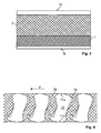
- Fig. 4 shows a section of a second embodiment of the freewheel installation element.
- This in Fig. 4 illustrated freewheel installation element is band-shaped and can be divided to the desired circumferential length and between an inner contact surface 4 (in Fig. 4 not shown) and an external contact surface 3 (in Fig. 4 not shown) are inserted.
- freewheel insert element fills the intermediate element 2 in the circumferential direction between two adjacent clamping bodies 11 space substantially completely, so that the contour of the clamp body 11 is completely up to the outer contact surface 1a and the inner contact surface 1 b with the intermediate element 2a and 2b in contact.
- Fig. 4 shows the clamping body 11 at the same time in its freewheeling position and - the freewheeling position partially overlapping - in its clamping position.
- the clamping body 11 In the clamping position are the clamping body 11, when the external contact surface 1 a by forming a frictional contact in the direction of rotation V relative to the inner contact surface 1 b is rotated and both contact surfaces 1 a and 1 b a frictional contact with the in Fig. 4 form clamps, not shown.
- the adjacent to the respective clamping bodies intermediate elements 2 - for example, the intermediate elements 2a and 2b with respect to the in Fig. 4 provided with the reference clamp body 11 - are firmly connected to the clamp body and deform due to their elastic material behavior in the displacement of the clamp body 11 of the freewheeling position in the clamping position or during its displacement from the clamping position to the freewheeling position accordingly.
- the adjacent intermediate elements 2a and 2b are made of different materials, in particular of materials with different elasticity.
- Fig. 5 shows a freewheel with a freewheel installation element, which consists of a plurality of clamping bodies 1 and intermediate elements 2.
- the outer surface of the inner ring 6 forms the inner clamping track 4.
- the inner ring 6 and the outer ring 5 are arranged concentrically to one another and between the outer clamping track 3 and the inner clamping track 4 is the freewheel mounting element with the clamping bodies 1 and attached the intermediate elements 2.
Landscapes
- General Engineering & Computer Science (AREA)
- Engineering & Computer Science (AREA)
- Mechanical Engineering (AREA)
- Pulleys (AREA)
- Rolling Contact Bearings (AREA)
- Window Of Vehicle (AREA)
- Valve Device For Special Equipments (AREA)
- Braking Arrangements (AREA)
- Mechanical Operated Clutches (AREA)
- Transition And Organic Metals Composition Catalysts For Addition Polymerization (AREA)
- Medicines That Contain Protein Lipid Enzymes And Other Medicines (AREA)
- Springs (AREA)
- Clamps And Clips (AREA)
Description
- Die Erfindung betrifft ein Freilaufeinbauelement und einen Freilauf. Freilaufeinbauelemente finden in Freiläufen, d. h. in Richtungskupplungen, die in eine Richtung ein Drehmoment durch Kraftschluss übertragen bzw. abstützen und in der Gegenrichtung Leerlauf zulassen, Anwendung. Bei Freiläufen mit Klemmkörpern befinden sich die Klemmkörper in der sog. Klemmposition, wenn sie das Drehmoment kraftschlüssig, d.h. reibschlüssig übertragen und in der sog. Freilaufposition, wenn sie Leerlauf zulassen.
- Bei herkömmlichen Freiläufen mit Klemmkörpern besteht das Freilaufeinbauelement aus den folgenden drei Elementen: den Klemmkörpern, dem Käfig und den Federn. Die Klemmkörper sind mittels Federkraft in Kontakt mit einer äußeren und einer inneren zylindrischen Klemmbahn zu bringen. Die Klemmkörper werden in einem sog. Käfig in gleichem Abstand am Umfang verkeilt gehalten, wobei auf jedem Klemmkörper eine Federkraft wirkt, die sich am Käfig abstützt. Derartige Freilaufeinbauelemente bekannter Bauart bestehen daher aus mindestens drei verschiedenen Komponenten, was einen entsprechend hohen Fertigungsaufwand nach sich zieht.
- Eine gattungsgemäße Freilaufbauelement bzw, ein gattungsgemäßer Freilauf ist aus
US-A-2,793,279 bekannt. - Aufgabe der vorliegenden Erfindung ist es, ein Freilaufeinbauelement und einen Freilauf zur Verfügung zu stellen, bei der das Ansprechverhalter über einer weiter Bereich angepasst werden kann.
- Diese Aufgabe wird für das Freilaufelement durch die Merkmale des Patentanspruchs 1 gelöst. Vorteilhafte Ausführungsformen des Freilaufelements sind in den Unteransprüchen 2 - 12 beschrieben. Für den Freilauf wird die Aufgabe durch die Merkmale des Patentanspruchs 13 gelöst.
- Vorteilhafte Ausführungsformen des Freilaufs sind in den Unteransprüchen 14 und 15 beschrieben.
- Das erfindungsgemäße Freilaufeinbauelement weist einer Vielzahl von Klemmkörpern auf, wobei jeder Klemmkörper eine Außenkontaktfläche zur Ausbildung eines reibschlüssigen Kontakts mit einer Außenklemmbahn und eine Innenkontaktfläche zur Ausbildung eines reibschlüssigen Kontakts mit einer Innenklemmbahn aufweist, und wobei eine Vielzahl von Zwischenelementen vorgesehen ist, die eine höhere Elastizität als die Klemmkörper aufweisen und zwischen benachbarten Klemmkörpern angeordnet sind. Außerden bestehen zweinander liegende Zwischenelemente aus verschiedenen Werkstoffen.
- Durch einen derartigen Aufbau können der Käfig und die Federn entfallen, was zu einem besonders einfach aufgebauten und einfach zu fertigenden Freilaufeinbauelement führt. Durch die im Vergleich zu den Klemmkörpern höhere Elastizität der Zwischenelemente wird die Verformbarkeit der Klemmkörper innerhalb des Freilaufeinbauelements sowie die Verformbarkeit des Freilaufeinbauelements selbst erhöht.
- Die Klemmkörper sind bevorzugt aus einem metallischen Material, z.B. aus einem Stahlwerkstoff. Entsprechend weisen die Zwischenelemente dann eine Elastizität auf, die größer ist als die Elastizität von metallischen Werkstoffen.
- Der Werkstoff bzw. die Werkstoffe, aus dem das Zwischenelement aufgebaut ist, besitzen in bevorzugter Weise eine Shorehärte von 30 Shore A bis 80 Shore A. Die Shore-Härte ist eine weit verbreitete Kenngröße zur Prüfung von Kunststoffen und Elastomeren und ist in den Normen DIN 53505, ISO 868 und ISO 7619 beschrieben.
- In vorteilhafter Weise sind die Zwischenelemente derart ausgebildet, die Klemmkörper in ihrer Lage zu fixieren und abzufedern. Durch ein gleichzeitiges Fixieren und Abfedern der Klemmkörper durch die Zwischenelemente ist eine besonders kompakte Bauweise des Freilaufeinbauelements möglich.
- Bestehen die Zwischenelemente aus elastischen Materialien mit hoher Eigendämpfung, z. B. aus Kautschuk, dann führt die Kippbewegung beim Einrollen der Klemmkörper zu einer Verformung des zwischen den Klemmkörpern angeordneten dämpfenden Materials der Zwischenelemente und damit zum Entzug von Schwingungsenergie, was zu einer besonders ausgeprägten Dämpfung durch das Freilaufelement führt.
- In einer vorteilhaften Ausführungsform sind die Zwischenelemente mit den Klemmkörpern verbunden. Insbesondere können die Zwischenelemente stoffschlüssig mit den Klemmkörpern verbunden sein, was zu einem besonders zuverlässigen und stabilen Verbund von Zwischenelementen und Klemmkörpern führt und dadurch beispielsweise die Handhabbarkeit des Freilaufeinbauelements verbessert. Hierbei kann die stoffschlüssige Verbindung beispielsweise als Klebeverbindung ausgeführt sein. Auch können die Zwischenelemente als Gießmasse bzw. mehrere Gießmassen ausgestaltet sein und die stoffschlüssige Verbindung durch einen Gießprozess, in dem die Klemmkörper - zumindest teilweise - durch die Gießmasse bzw. Gießmassen umschlossen werden, hergestellt werden. Auch ist es möglich, die Zwischenelemente aus einer Spritzgussmasse bzw. Spritzgussmassen herzustellen und die Zwischenelemente mit Hilfe eines Spritzgussprozesses mit den Klemmkörpern zu verbinden.
- In einer weiteren vorteilhaften Ausführungsform entsprechen die Zwischenelemente in ihrer Kontur der Kontur der benachbarten Klemmkörper. Eine derartige Ausgestaltung der Kontur erlaubt eine besonders zuverlässige Verbindung zwischen dem Zwischenelement und den an diesen angrenzenden Klemmkörper.
- Erfindungsgemäß bestehen die Zwischenelemente aus mehreren unterschiedlichen Werkstoffen. Hierbei ist es vorgesehen, dass benachbart zueinander liegende Zwischenelemente aus unterschiedlichen Werkstoffen bestehen, zum anderen ist es auch möglich, dass ein Zwischenelement selbst aus verschiedenen Werkstoffen aufgebaut ist. Insgesamt wird dadurch die Variabilität und Anpassbarkeit des Freilaufelements an verschiedene Einsatzgebiete erhöht.
- In einer weiteren vorteilhaften Ausführungsform variiert die Elastizität mindestens eines Zwischenelements entlang der Richtung von der Innenklemmbahn zur Außenklemmbahn. Diese Variation in der Elastizität kann beispielsweise durch den Aufbau des Zwischenelements durch verschiedene Werkstoffe bzw. durch eine graduelle Variation der Elastizität des verwendeten Werkstoffs erreicht werden. Die Variation der Elastizität erhöht ebenfalls die Anpassbarkeit des Freilaufeinbauelements.
- Je nach gewünschtem Einsatzgebiet und je nach gewünschter Elastizität können die Zwischenelemente aus in bevorzugten Ausführungsformen zumindest teilweise aus Silikonwerkstoff, aus thermoplastischen Polymeren, aus vulkanisiertem Kautschuk, aus duroplastischen Polymeren (z.B. Kunstharz), aus Elastomeren oder aus einer Mischung der vorgenannten Werkstoffe hergestellt sein. Nach der Erfindung variiert die Werkstoffzusammensetzung von Zwischenelement zu Zwischenelement. Dies erhöht die Variabilität des Freilaufeinbauelements sowie dessen Anpassbarkeit an verschiedene Anwendungsfälle.
- In einer weiteren vorteilhaften Ausführungsform ist das Freilaufeinbauelement bandförmig ausgebildet. Hierdurch ist die Herstellung des Freilaufeinbauelements als endloses Band möglich. Nach der Herstellung kann das Freilaufeinbauelement dann auf die gewünschte Umlauflänge zerteilt und zwischen eine Innenkontaktfläche und eine Außenkontaktfläche eingelegt werden.
- In einer weiteren vorteilhaften Ausführungsform ist das Freilaufeinbauelement ringförmig ausgebildet. Dadurch kann das Freilaufeinbauelement besonders einfach in einem Freilauf eingebaut werden und ermöglicht einen reibschlüssigen Kontakt über den gesamten Umfang der Außen- bzw. Innenklemmbahn.
- Der erfindungsgemäße Freilauf weist einen Innenring, dessen äußere Mantelfläche eine Innenklemmbahn bildet, und einem Außenring, dessen innere Mantelfläche eine Außenklemmbahn bildet, und ein zwischen der Innenklemmbahn und der Außenklemmbahn angeordnetes erfindungsgemäßes Freilaufeinbauelement auf.
- In einer bevorzugten Ausführungsform des Freilaufes ist zumindest ein Teil der Klemmkörper in ihrer Klemmposition mit den Zwischenelementen verbunden. Insbesondere können Klemmkörper derart relativ zu den Zwischenelementen angeordnet sein, d.h. beispielsweise in die Zwischenelemente eingebettet sein, dass die Klemmkörper um ihren Klemmwinkel gegenüber den Klemmbahnen verkippt ist.
- In einer weiteren Ausführungsform kann zumindest ein Teil der Klemmkörper in ihrer Freilaufposition mit den Zwischenelementen verbunden sein.
- In Freilaufeinbauelementen bzw. in Freiläufen, die viel im Freilauf betrieben werden, bestehen die Zwischenelemente in besonders bevorzugter Weise aus sehr elastischem Material, um die Reibung zwischen Klemmkörper und Klemmbahnen niedrig zu halten.
- Die Erfindung ist anhand von Ausführungsbeispielen in den Zeichnungsfiguren weiter erläutert. Es zeigen:
- Fig. 1
- eine erste Ausführungsform des Freilaufeinbauelements;
- Fig. 2
- einen vergrößerten Ausschnitt aus dem in
Fig. 1 dargestellten Freilaufeinbauelement; - Fig. 3
- eine Schnittdarstellung des in
Fig. 2 dargestellten Freilaufeinbauelements; - Fig. 4
- eine zweite Ausführungsform des Freilaufeinbauelements;
- Fig. 5
- einen Freilauf.
-
Fig. 1 zeigt ein Freilaufeinbauelement mit einer Vielzahl von Klemmkörpern 1 und Zwischenelementen 2, wobei in Figuren in der Regel jeweils nur ein Klemmkörper 1 und ein Zwischenelement 2 mit einem Bezugszeichen versehen sind. Das Freilaufeinbauelement ist ringförmig ausgebildet und die Klemmkörper 1 sowie die Zwischenelemente 2 sind gleichmäßig über den Umfang verteilt. -
Fig. 2 zeigt einen vergrößerten Ausschnitt ausFig. 1 . Der Klemmkörper 1 weist eine Außenkontaktfläche 1 a zur Ausbildung eines reibschlüssigen Kontakts mit einer Außenklemmbahn 3 und eine Innenkontaktfläche 1 b zur Ausbildung eines reibschlüssigen Kontakts mit einer Innenklemmbahn 4 auf. Zwischen den Klemmkörpern 1 befindet sich jeweils ein Zwischenelement 2. Der Klemmkörper 1 ist hierbei bezüglich der Außenklemmbahn 3 bzw. der Innenklemmbahn 4 verkippt in die Zwischenelemente 2 eingebettet. Mit anderen Worten ist die Klemmkörperachse A des Klemmkörpers 1 nicht in radialer Richtung ausgerichtet, sondern schließt mit der radialen Richtung R den Winkel ϕ ein. -
Fig. 3 zeigt eine Schnittdarstellung entlang der inFig. 2 eingezeichneten Schnittfläche III-III. Das Zwischenelement 2 besitzt eine axiale Ausdehnung, die der axialen Ausdehnung des Klemmkörpers 1 entspricht. Durch die Begrenzung der Ausdehnung des Zwischenelements 2 in axialer Richtung auf die Ausdehnung des Klemmkörpers 1 ist ein besonders kompaktes Freilaufeinbauelement herstellbar. - In einer weiteren, nicht in den Zeichnungsfiguren dargestellten Ausführungsform, kann das Zwischenelement 2 den Klemmkörper 1 auch in axialer Richtung überragen. Dies führt zu einer besonders lagestabilen Anordnung der einzelnen Klemmkörper 1 innerhalb der Zwischenelemente 2.
-
Fig. 4 zeigt einen Ausschnitt aus einer zweiten Ausführungsform des Freilaufeinbauelements. Das inFig. 4 dargestellte Freilaufeinbauelement ist bandförmig ausgebildet und kann auf die gewünschte Umlauflänge zerteilt und zwischen eine Innenkontaktfläche 4 (inFig. 4 nicht dargestellt) und eine Außenkontaktfläche 3 (inFig. 4 nicht dargestellt) eingelegt werden. - Im Unterschied zu dem in
Fig. 1 und Fig. 2 dargestellten Freilaufeinbauelement füllt das Zwischenelement 2 den in Umfangsrichtung zwischen zwei benachbarten Klemmkörpern 11 gelegenen Raum im Wesentlichen vollständig aus, sodass die Kontur des Klemmkörpers 11 bis auf die Außenkontaktfläche 1a und die Innenkontaktfläche 1 b vollständig mit dem Zwischenelement 2a bzw. 2b in Kontakt steht. -
Fig. 4 zeigt die Klemmkörper 11 zugleich in ihrer Freilaufposition und - die Freilaufposition teilweise überlagernd - in ihrer Klemmposition. In der Klemmposition befinden sich die Klemmkörper 11, wenn die Außenkontaktfläche 1 a durch Ausbildung eines reibschlüssigen Kontakts in die Verdrehrichtung V relativ zur Innenkontaktfläche 1 b verdreht wird und beide Kontaktflächen 1 a und 1 b einen reibschlüssigen Kontakt mit den inFig. 4 nicht dargestellten Klemmbahnen ausbilden. Die benachbart zu den jeweiligen Klemmkörpern liegenden Zwischenelemente 2 - beispielsweise die Zwischenelemente 2a und 2b bezüglich des inFig. 4 mit dem Bezugszeichen versehenen Klemmkörper 11 - sind mit dem Klemmkörper fest verbunden und verformen sich aufgrund ihres elastischen Werkstoffverhaltens bei der Verschiebung des Klemmkörpers 11 von dessen Freilaufposition in dessen Klemmposition bzw. bei dessen Verschiebung von der Klemmposition in die Freilaufposition entsprechend. - Erfindungsgemäß sind die benachbart zueinander liegenden Zwischenelemente 2a und 2b aus verschiedenen Werkstoffen, insbesondere aus Werkstoffen mit unterschiedlicher Elastizität, hergestellt.
-
Fig. 5 zeigt einen Freilauf mit einem Freilaufeinbauelement, welches aus einer Vielzahl von Klemmkörpern 1 und Zwischenelementen 2 besteht. Die innerer Mantelfläche des Außenrings 5 bildet die Außenklemmbahn 3. Die äußere Mantelfläche des Innenrings 6 bildet die Innenklemmbahn 4. Der Innenring 6 und der Außenring 5 sind konzentrisch zueinander angeordnet und zwischen die Außenklemmbahn 3 und der Innenklemmbahn 4 ist das Freilaufeinbauelement mit den Klemmkörpern 1 und den Zwischenelementen 2 angebracht. -
- 1
- Klemmkörper
- 1a
- Außenkontaktfläche
- 1b
- Innenkontaktfläche
- 2, 2a, 2b
- Zwischenelement
- 3
- Außenklemmbahn
- 4
- Innenklemmbahn
- 5
- Außenring
- 6
- Innenring
- 11
- Klemmkörper
- 11a
- Außenkontaktfläche
- 11b
- Innenkontaktfläche
- A
- Klemmkörperachse
- R
- radiale Richtung
- V
- Verdrehrichtung
- ϕ
- Winkel
Claims (15)
- Freilaufeinbauelement mit einer Vielzahl von Klemmkörpern (1, 11), wobei jeder Klemmkörper (1, 11) eine Außenkontaktfläche (1a, 11a) zur Ausbildung eines reibschlüssigen Kontakts mit einer Außenklemmbahn (3) und eine Innenkontaktfläche (1 b, 11 b) zur Ausbildung eines reibschlüssigen Kontakts mit einer Innenklemmbahn (4) aufweist, und wobei eine Vielzahl von Zwischenelementen (2, 2a, 2b) vorgesehen ist, die eine höhere Elastizität als die Klemmkörper (1, 11) aufweisen und zwischen benachbarten Klemmkörpern (1, 11) angeordnet sind,
gekennzeichnet dadurch, dass
benachbart zueinander liegende Zwischenelemente (2, 2a, 2b) aus verschiedenen Werkstoffen, insbesondere aus Werkstoffen mit unterschiedlicher Elastizität, bestehen. - Freilaufeinbauelement nach Anspruch 1, wobei die Zwischenelemente (2, 2a, 2b) derart ausgebildet sind, die Klemmkörper (1, 11) in ihrer Lage zu fixieren und abzufedern.
- Freilaufeinbauelement nach einen der vorhergehenden Ansprüche, wobei die Zwischenelemente (2, 2a, 2b) mit den Klemmkörpern (1, 11) verbunden, insbesondere stoffschlüssig verbunden, sind.
- Freilaufeinbauelement nach einen der vorhergehenden Ansprüche, wobei die Zwischenelemente (2, 2a, 2b) in ihrer Kontur der Kontur der benachbarten Klemmkörper (1, 11) entsprechen.
- Freilaufeinbauelement nach einen der vorhergehenden Ansprüche, wobei die Zwischenelemente (2, 2a, 2b) jeweils aus mehreren unterschiedlichen Werkstoffen bestehen.
- Freilaufeinbauelement nach einen der vorhergehenden Ansprüche, wobei die Elastizität mindestens eines Zwischenelements (2, 2a, 2b) entlang der Richtung von der Innenklemmbahn (4) zur Außenklemmbahn (3) variiert.
- Freilaufeinbauelement nach einen der vorhergehenden Ansprüche, wobei die Zwischenelemente (2, 2a, 2b) teilweise aus einem Silikon bestehen.
- Freilaufeinbauelement nach einen der vorhergehenden Ansprüche, wobei die Zwischenelemente (2, 2a, 2b) teilweise aus einem thermoplastischen Polymer bestehen.
- Freilaufeinbauelement nach einen der vorhergehenden Ansprüche, wobei die Zwischenelemente (2, 2a, 2b) teilweise aus einem Elastomer, insbesondere einem vulkanisierten Kautschuk, bestehen.
- Freilaufeinbauelement nach einen der vorhergehenden Ansprüche, wobei die Zwischenelemente (2, 2a, 2b) teilweise aus einem duroplastischen Polymer, insbesondere einem Kunstharz, bestehen.
- Freilaufeinbauelement nach einen der vorhergehenden Ansprüche, wobei das Freilaufeinbauelement bandförmig ausgebildet ist.
- Freilaufeinbauelement nach einen der vorhergehenden Ansprüche 1 bis 10, wobei das Freilaufeinbauelement ringförmig ausgebildet ist.
- Freilauf, mit einem Innenring (6), dessen äußere Mantelfläche eine Innenklemmbahn (4) bildet, und einem Außenring (5), dessen innere Mantelfläche eine Außenklemmbahn (3) bildet und einem zwischen der Innenklemmbahn (4) und der Außenklemmbahn (3) angeordneten Freilaufeinbauelement nach einem der Ansprüche 1 - 12.
- Freilauf nach Anspruch 13, wobei zumindest ein Teil der Klemmkörper (1, 11) in ihrer Klemmposition mit den Zwischenelementen (2, 2a, 2b) verbunden ist.
- Freilauf nach Anspruch 13 - 14, wobei zumindest ein Teil der Klemmkörper (1, 11) in ihrer Freilaufposition (2, 2a, 2b) mit den Zwischenelementen verbunden ist.
Priority Applications (8)
| Application Number | Priority Date | Filing Date | Title |
|---|---|---|---|
| AT08172346T ATE544967T1 (de) | 2008-12-19 | 2008-12-19 | Freilaufeinbauelement und freilauf |
| EP08172346A EP2199635B1 (de) | 2008-12-19 | 2008-12-19 | Freilaufeinbauelement und Freilauf |
| DE112009003190T DE112009003190A5 (de) | 2008-12-19 | 2009-12-17 | Freilaufeinbauelement und freilauf |
| KR1020117014016A KR101606611B1 (ko) | 2008-12-19 | 2009-12-17 | 프리휠 인써트 엘리먼트 및 프리휠 |
| PCT/DE2009/075076 WO2010069308A1 (de) | 2008-12-19 | 2009-12-17 | Freilaufeinbauelement und freilauf |
| JP2011541085A JP5555712B2 (ja) | 2008-12-19 | 2009-12-17 | フリーホイール挿入要素およびフリーホイール |
| US12/998,906 US8528713B2 (en) | 2008-12-19 | 2009-12-17 | Freewheel insert element and freewheel |
| TW098143562A TWI465653B (zh) | 2008-12-19 | 2009-12-18 | 飛輪構件與飛輪 |
Applications Claiming Priority (1)
| Application Number | Priority Date | Filing Date | Title |
|---|---|---|---|
| EP08172346A EP2199635B1 (de) | 2008-12-19 | 2008-12-19 | Freilaufeinbauelement und Freilauf |
Publications (2)
| Publication Number | Publication Date |
|---|---|
| EP2199635A1 EP2199635A1 (de) | 2010-06-23 |
| EP2199635B1 true EP2199635B1 (de) | 2012-02-08 |
Family
ID=40612782
Family Applications (1)
| Application Number | Title | Priority Date | Filing Date |
|---|---|---|---|
| EP08172346A Not-in-force EP2199635B1 (de) | 2008-12-19 | 2008-12-19 | Freilaufeinbauelement und Freilauf |
Country Status (8)
| Country | Link |
|---|---|
| US (1) | US8528713B2 (de) |
| EP (1) | EP2199635B1 (de) |
| JP (1) | JP5555712B2 (de) |
| KR (1) | KR101606611B1 (de) |
| AT (1) | ATE544967T1 (de) |
| DE (1) | DE112009003190A5 (de) |
| TW (1) | TWI465653B (de) |
| WO (1) | WO2010069308A1 (de) |
Family Cites Families (19)
| Publication number | Priority date | Publication date | Assignee | Title |
|---|---|---|---|---|
| US2614670A (en) * | 1946-08-14 | 1952-10-21 | Jack & Heintz Prec Ind Inc | Sprag type overrunning clutch |
| US2520004A (en) * | 1946-12-23 | 1950-08-22 | Northern Ordnance Inc | Sprag type overrunning clutch |
| US2624436A (en) * | 1947-01-02 | 1953-01-06 | Borg Warner | Sprag type clutch |
| US2793729A (en) * | 1954-02-18 | 1957-05-28 | Gen Motors Corp | One-way clutch |
| US2812839A (en) * | 1954-02-18 | 1957-11-12 | Gen Motors Corp | One-way clutch |
| US2803324A (en) * | 1954-05-03 | 1957-08-20 | Adiel Y Dodge | One-way clutch |
| US3324980A (en) | 1965-07-06 | 1967-06-13 | Borg Warner | Elastomer cage for sprag members |
| DE2758841C2 (de) | 1977-12-30 | 1986-09-04 | Stieber Division Der Borg-Warner Gmbh, 6900 Heidelberg | Klemmkörper-Freilaufkupplung |
| US5052533A (en) * | 1987-02-09 | 1991-10-01 | Borg-Warner Corporation | One-way clutch energizing spring |
| US4998605A (en) * | 1990-02-12 | 1991-03-12 | Ferris Ernest A | Plastic cage for a one-way clutch |
| DE4032915A1 (de) * | 1990-10-17 | 1992-04-23 | Hermann Grothe | Welle-nabe-verbindung |
| US5445255A (en) * | 1993-07-08 | 1995-08-29 | Borg-Warner Automotive, Inc. | Sprag one-way clutch with inertia resistance members |
| US5607036A (en) * | 1995-03-03 | 1997-03-04 | Borg-Warner Automotive, Inc. | One-way clutch with stretchable spring member |
| JP2001001364A (ja) * | 1999-06-21 | 2001-01-09 | Canon Inc | 樹脂成形品 |
| CN1441176A (zh) * | 2002-02-28 | 2003-09-10 | 陆大雄 | 止逆滚动轴承 |
| JP2006077937A (ja) * | 2004-09-13 | 2006-03-23 | Kazuo Ishikawa | ワンウェイクラッチ |
| JP2006292140A (ja) | 2005-04-14 | 2006-10-26 | Nsk Warner Kk | スプラグ型ワンウェイクラッチ |
| JP2008014427A (ja) | 2006-07-07 | 2008-01-24 | Ntn Corp | 一方向クラッチ付き軸受装置 |
| EP2199643B1 (de) * | 2008-12-19 | 2016-06-08 | Paul Müller GmbH & Co. KG Unternehmensbeteiligungen | Drehschwingungsdämpfer und Spindel |
-
2008
- 2008-12-19 AT AT08172346T patent/ATE544967T1/de active
- 2008-12-19 EP EP08172346A patent/EP2199635B1/de not_active Not-in-force
-
2009
- 2009-12-17 US US12/998,906 patent/US8528713B2/en not_active Expired - Fee Related
- 2009-12-17 JP JP2011541085A patent/JP5555712B2/ja not_active Expired - Fee Related
- 2009-12-17 KR KR1020117014016A patent/KR101606611B1/ko not_active Expired - Fee Related
- 2009-12-17 DE DE112009003190T patent/DE112009003190A5/de not_active Withdrawn
- 2009-12-17 WO PCT/DE2009/075076 patent/WO2010069308A1/de not_active Ceased
- 2009-12-18 TW TW098143562A patent/TWI465653B/zh not_active IP Right Cessation
Also Published As
| Publication number | Publication date |
|---|---|
| US20110240434A1 (en) | 2011-10-06 |
| TWI465653B (zh) | 2014-12-21 |
| KR101606611B1 (ko) | 2016-03-25 |
| US8528713B2 (en) | 2013-09-10 |
| KR20110114537A (ko) | 2011-10-19 |
| JP2012512366A (ja) | 2012-05-31 |
| ATE544967T1 (de) | 2012-02-15 |
| EP2199635A1 (de) | 2010-06-23 |
| WO2010069308A1 (de) | 2010-06-24 |
| JP5555712B2 (ja) | 2014-07-23 |
| TW201030253A (en) | 2010-08-16 |
| DE112009003190A5 (de) | 2012-07-05 |
Similar Documents
| Publication | Publication Date | Title |
|---|---|---|
| DE2250003A1 (de) | Rotationskolbenmaschine, insbesondere maschine der fluegelzellenbauart, mit axial festgelegtem rotor | |
| WO2007098745A1 (de) | Zahnradanordnung | |
| DE102010024903A1 (de) | Vorrichtung zum elastischen Lagern eines Motors und Verfahren zum Herstellen desselben | |
| EP0503135B1 (de) | Elastische Kupplung mit zusammengefasster Lagerung und Drehbegrenzung | |
| EP2198175A2 (de) | Wälzlager, wälzlageranordnung und maschine, insbesondere elektrisches hausgerät | |
| EP1041318A2 (de) | Dichtring | |
| EP2199643B1 (de) | Drehschwingungsdämpfer und Spindel | |
| WO2017162837A1 (de) | Dichtungsanordnung, bausatz für eine dichtungsanordnung und verfahren zur herstellung einer dichtungsanordnung | |
| WO2009124677A1 (de) | Freilaufkupplung | |
| DE4220515A1 (de) | Nadellager mit geteiltem nadelkaefig | |
| WO2013149914A1 (de) | Halter zur befestigung einer komponente an einer brennkraftmaschine, lagerbuchse für solch einen halter und brennstoffeinspritzanlage | |
| DE202007012050U1 (de) | Dichtungselement, insbesondere Sekundärdichtungselement einer Gleitringdichtung | |
| EP2199635B1 (de) | Freilaufeinbauelement und Freilauf | |
| DE602004006417T2 (de) | Vorrichtung und freilaufgehäuse | |
| EP1323958B1 (de) | Dichtring | |
| EP2962017A1 (de) | Flachdichtung für flanschverbindungen | |
| WO2019238959A1 (de) | Schraubenfeder einer kraftfahrzeugfederung, verfahren zu deren herstellung sowie kraftfahrzeugfederung | |
| EP3110680B1 (de) | Lenkwelle für ein kraftfahrzeug | |
| DE1045183B (de) | Huelsenfoermige Gummimetallfeder mit nierenfoermigen Ausnehmungen fuer elastische Kupplungen | |
| DE102012001283B4 (de) | Positioniervorrichtung für einen Fahrzeuggurtbringer und Gurtschlossvorrichtung | |
| EP3251999B1 (de) | Reifen für eine seilrolle, seilrolle und verfahren zur herstellung eines reifens für eine seilrolle | |
| DE102010021409A1 (de) | Schaltbare Kupplung | |
| DE102014201019A1 (de) | Ausrücksystem | |
| EP3101306B1 (de) | Torsionsdämpfer | |
| EP3842671B1 (de) | Wellendichtung, insbesondere radialwellendichtung, mit wenigstens einem dichtelement |
Legal Events
| Date | Code | Title | Description |
|---|---|---|---|
| PUAI | Public reference made under article 153(3) epc to a published international application that has entered the european phase |
Free format text: ORIGINAL CODE: 0009012 |
|
| AK | Designated contracting states |
Kind code of ref document: A1 Designated state(s): AT BE BG CH CY CZ DE DK EE ES FI FR GB GR HR HU IE IS IT LI LT LU LV MC MT NL NO PL PT RO SE SI SK TR |
|
| AX | Request for extension of the european patent |
Extension state: AL BA MK RS |
|
| 17P | Request for examination filed |
Effective date: 20100928 |
|
| 17Q | First examination report despatched |
Effective date: 20101021 |
|
| AKX | Designation fees paid |
Designated state(s): AT BE BG CH CY CZ DE DK EE ES FI FR GB GR HR HU IE IS IT LI LT LU LV MC MT NL NO PL PT RO SE SI SK TR |
|
| RIC1 | Information provided on ipc code assigned before grant |
Ipc: F16D 41/07 20060101AFI20110714BHEP |
|
| GRAP | Despatch of communication of intention to grant a patent |
Free format text: ORIGINAL CODE: EPIDOSNIGR1 |
|
| GRAS | Grant fee paid |
Free format text: ORIGINAL CODE: EPIDOSNIGR3 |
|
| GRAA | (expected) grant |
Free format text: ORIGINAL CODE: 0009210 |
|
| AK | Designated contracting states |
Kind code of ref document: B1 Designated state(s): AT BE BG CH CY CZ DE DK EE ES FI FR GB GR HR HU IE IS IT LI LT LU LV MC MT NL NO PL PT RO SE SI SK TR |
|
| REG | Reference to a national code |
Ref country code: GB Ref legal event code: FG4D Free format text: NOT ENGLISH |
|
| REG | Reference to a national code |
Ref country code: AT Ref legal event code: REF Ref document number: 544967 Country of ref document: AT Kind code of ref document: T Effective date: 20120215 Ref country code: CH Ref legal event code: EP |
|
| REG | Reference to a national code |
Ref country code: DE Ref legal event code: R082 Ref document number: 502008006339 Country of ref document: DE Representative=s name: LOESCH, CHRISTOPH, DIPL.-WIRTSCH.-ING., DE Ref country code: DE Ref legal event code: R082 Ref document number: 502008006339 Country of ref document: DE Representative=s name: CHRISTOPH LOESCH, DE |
|
| REG | Reference to a national code |
Ref country code: DE Ref legal event code: R096 Ref document number: 502008006339 Country of ref document: DE Effective date: 20120405 |
|
| REG | Reference to a national code |
Ref country code: NL Ref legal event code: VDEP Effective date: 20120208 |
|
| LTIE | Lt: invalidation of european patent or patent extension |
Effective date: 20120208 |
|
| PG25 | Lapsed in a contracting state [announced via postgrant information from national office to epo] |
Ref country code: NO Free format text: LAPSE BECAUSE OF FAILURE TO SUBMIT A TRANSLATION OF THE DESCRIPTION OR TO PAY THE FEE WITHIN THE PRESCRIBED TIME-LIMIT Effective date: 20120508 Ref country code: HR Free format text: LAPSE BECAUSE OF FAILURE TO SUBMIT A TRANSLATION OF THE DESCRIPTION OR TO PAY THE FEE WITHIN THE PRESCRIBED TIME-LIMIT Effective date: 20120208 Ref country code: IS Free format text: LAPSE BECAUSE OF FAILURE TO SUBMIT A TRANSLATION OF THE DESCRIPTION OR TO PAY THE FEE WITHIN THE PRESCRIBED TIME-LIMIT Effective date: 20120608 Ref country code: NL Free format text: LAPSE BECAUSE OF FAILURE TO SUBMIT A TRANSLATION OF THE DESCRIPTION OR TO PAY THE FEE WITHIN THE PRESCRIBED TIME-LIMIT Effective date: 20120208 Ref country code: LT Free format text: LAPSE BECAUSE OF FAILURE TO SUBMIT A TRANSLATION OF THE DESCRIPTION OR TO PAY THE FEE WITHIN THE PRESCRIBED TIME-LIMIT Effective date: 20120208 |
|
| REG | Reference to a national code |
Ref country code: IE Ref legal event code: FD4D |
|
| PG25 | Lapsed in a contracting state [announced via postgrant information from national office to epo] |
Ref country code: PL Free format text: LAPSE BECAUSE OF FAILURE TO SUBMIT A TRANSLATION OF THE DESCRIPTION OR TO PAY THE FEE WITHIN THE PRESCRIBED TIME-LIMIT Effective date: 20120208 Ref country code: LV Free format text: LAPSE BECAUSE OF FAILURE TO SUBMIT A TRANSLATION OF THE DESCRIPTION OR TO PAY THE FEE WITHIN THE PRESCRIBED TIME-LIMIT Effective date: 20120208 Ref country code: FI Free format text: LAPSE BECAUSE OF FAILURE TO SUBMIT A TRANSLATION OF THE DESCRIPTION OR TO PAY THE FEE WITHIN THE PRESCRIBED TIME-LIMIT Effective date: 20120208 Ref country code: PT Free format text: LAPSE BECAUSE OF FAILURE TO SUBMIT A TRANSLATION OF THE DESCRIPTION OR TO PAY THE FEE WITHIN THE PRESCRIBED TIME-LIMIT Effective date: 20120608 Ref country code: GR Free format text: LAPSE BECAUSE OF FAILURE TO SUBMIT A TRANSLATION OF THE DESCRIPTION OR TO PAY THE FEE WITHIN THE PRESCRIBED TIME-LIMIT Effective date: 20120509 |
|
| PG25 | Lapsed in a contracting state [announced via postgrant information from national office to epo] |
Ref country code: CY Free format text: LAPSE BECAUSE OF FAILURE TO SUBMIT A TRANSLATION OF THE DESCRIPTION OR TO PAY THE FEE WITHIN THE PRESCRIBED TIME-LIMIT Effective date: 20120208 |
|
| PG25 | Lapsed in a contracting state [announced via postgrant information from national office to epo] |
Ref country code: CZ Free format text: LAPSE BECAUSE OF FAILURE TO SUBMIT A TRANSLATION OF THE DESCRIPTION OR TO PAY THE FEE WITHIN THE PRESCRIBED TIME-LIMIT Effective date: 20120208 Ref country code: SE Free format text: LAPSE BECAUSE OF FAILURE TO SUBMIT A TRANSLATION OF THE DESCRIPTION OR TO PAY THE FEE WITHIN THE PRESCRIBED TIME-LIMIT Effective date: 20120208 Ref country code: IE Free format text: LAPSE BECAUSE OF FAILURE TO SUBMIT A TRANSLATION OF THE DESCRIPTION OR TO PAY THE FEE WITHIN THE PRESCRIBED TIME-LIMIT Effective date: 20120208 Ref country code: RO Free format text: LAPSE BECAUSE OF FAILURE TO SUBMIT A TRANSLATION OF THE DESCRIPTION OR TO PAY THE FEE WITHIN THE PRESCRIBED TIME-LIMIT Effective date: 20120208 Ref country code: SI Free format text: LAPSE BECAUSE OF FAILURE TO SUBMIT A TRANSLATION OF THE DESCRIPTION OR TO PAY THE FEE WITHIN THE PRESCRIBED TIME-LIMIT Effective date: 20120208 Ref country code: EE Free format text: LAPSE BECAUSE OF FAILURE TO SUBMIT A TRANSLATION OF THE DESCRIPTION OR TO PAY THE FEE WITHIN THE PRESCRIBED TIME-LIMIT Effective date: 20120208 Ref country code: DK Free format text: LAPSE BECAUSE OF FAILURE TO SUBMIT A TRANSLATION OF THE DESCRIPTION OR TO PAY THE FEE WITHIN THE PRESCRIBED TIME-LIMIT Effective date: 20120208 |
|
| PG25 | Lapsed in a contracting state [announced via postgrant information from national office to epo] |
Ref country code: SK Free format text: LAPSE BECAUSE OF FAILURE TO SUBMIT A TRANSLATION OF THE DESCRIPTION OR TO PAY THE FEE WITHIN THE PRESCRIBED TIME-LIMIT Effective date: 20120208 |
|
| PLBE | No opposition filed within time limit |
Free format text: ORIGINAL CODE: 0009261 |
|
| STAA | Information on the status of an ep patent application or granted ep patent |
Free format text: STATUS: NO OPPOSITION FILED WITHIN TIME LIMIT |
|
| 26N | No opposition filed |
Effective date: 20121109 |
|
| REG | Reference to a national code |
Ref country code: DE Ref legal event code: R097 Ref document number: 502008006339 Country of ref document: DE Effective date: 20121109 |
|
| BERE | Be: lapsed |
Owner name: PAUL MULLER G.M.B.H. & CO. KG UNTERNEHMENSBETEILI Effective date: 20121231 |
|
| PG25 | Lapsed in a contracting state [announced via postgrant information from national office to epo] |
Ref country code: BG Free format text: LAPSE BECAUSE OF FAILURE TO SUBMIT A TRANSLATION OF THE DESCRIPTION OR TO PAY THE FEE WITHIN THE PRESCRIBED TIME-LIMIT Effective date: 20120508 Ref country code: MC Free format text: LAPSE BECAUSE OF NON-PAYMENT OF DUE FEES Effective date: 20121231 |
|
| PG25 | Lapsed in a contracting state [announced via postgrant information from national office to epo] |
Ref country code: BE Free format text: LAPSE BECAUSE OF NON-PAYMENT OF DUE FEES Effective date: 20121231 |
|
| PG25 | Lapsed in a contracting state [announced via postgrant information from national office to epo] |
Ref country code: ES Free format text: LAPSE BECAUSE OF FAILURE TO SUBMIT A TRANSLATION OF THE DESCRIPTION OR TO PAY THE FEE WITHIN THE PRESCRIBED TIME-LIMIT Effective date: 20120519 |
|
| PG25 | Lapsed in a contracting state [announced via postgrant information from national office to epo] |
Ref country code: MT Free format text: LAPSE BECAUSE OF FAILURE TO SUBMIT A TRANSLATION OF THE DESCRIPTION OR TO PAY THE FEE WITHIN THE PRESCRIBED TIME-LIMIT Effective date: 20120208 |
|
| PG25 | Lapsed in a contracting state [announced via postgrant information from national office to epo] |
Ref country code: TR Free format text: LAPSE BECAUSE OF FAILURE TO SUBMIT A TRANSLATION OF THE DESCRIPTION OR TO PAY THE FEE WITHIN THE PRESCRIBED TIME-LIMIT Effective date: 20120208 |
|
| PG25 | Lapsed in a contracting state [announced via postgrant information from national office to epo] |
Ref country code: LU Free format text: LAPSE BECAUSE OF NON-PAYMENT OF DUE FEES Effective date: 20121219 |
|
| PG25 | Lapsed in a contracting state [announced via postgrant information from national office to epo] |
Ref country code: HU Free format text: LAPSE BECAUSE OF FAILURE TO SUBMIT A TRANSLATION OF THE DESCRIPTION OR TO PAY THE FEE WITHIN THE PRESCRIBED TIME-LIMIT Effective date: 20081219 |
|
| REG | Reference to a national code |
Ref country code: FR Ref legal event code: PLFP Year of fee payment: 8 |
|
| REG | Reference to a national code |
Ref country code: FR Ref legal event code: PLFP Year of fee payment: 9 |
|
| REG | Reference to a national code |
Ref country code: FR Ref legal event code: PLFP Year of fee payment: 10 |
|
| PGFP | Annual fee paid to national office [announced via postgrant information from national office to epo] |
Ref country code: IT Payment date: 20191216 Year of fee payment: 12 Ref country code: FR Payment date: 20191218 Year of fee payment: 12 |
|
| PGFP | Annual fee paid to national office [announced via postgrant information from national office to epo] |
Ref country code: AT Payment date: 20191213 Year of fee payment: 12 |
|
| PGFP | Annual fee paid to national office [announced via postgrant information from national office to epo] |
Ref country code: GB Payment date: 20191220 Year of fee payment: 12 |
|
| PGFP | Annual fee paid to national office [announced via postgrant information from national office to epo] |
Ref country code: CH Payment date: 20201222 Year of fee payment: 13 |
|
| REG | Reference to a national code |
Ref country code: AT Ref legal event code: MM01 Ref document number: 544967 Country of ref document: AT Kind code of ref document: T Effective date: 20201219 |
|
| GBPC | Gb: european patent ceased through non-payment of renewal fee |
Effective date: 20201219 |
|
| PG25 | Lapsed in a contracting state [announced via postgrant information from national office to epo] |
Ref country code: AT Free format text: LAPSE BECAUSE OF NON-PAYMENT OF DUE FEES Effective date: 20201219 Ref country code: IT Free format text: LAPSE BECAUSE OF NON-PAYMENT OF DUE FEES Effective date: 20201219 Ref country code: FR Free format text: LAPSE BECAUSE OF NON-PAYMENT OF DUE FEES Effective date: 20201231 |
|
| PG25 | Lapsed in a contracting state [announced via postgrant information from national office to epo] |
Ref country code: GB Free format text: LAPSE BECAUSE OF NON-PAYMENT OF DUE FEES Effective date: 20201219 |
|
| PGFP | Annual fee paid to national office [announced via postgrant information from national office to epo] |
Ref country code: DE Payment date: 20220217 Year of fee payment: 14 |
|
| REG | Reference to a national code |
Ref country code: CH Ref legal event code: PL |
|
| PG25 | Lapsed in a contracting state [announced via postgrant information from national office to epo] |
Ref country code: LI Free format text: LAPSE BECAUSE OF NON-PAYMENT OF DUE FEES Effective date: 20211231 Ref country code: CH Free format text: LAPSE BECAUSE OF NON-PAYMENT OF DUE FEES Effective date: 20211231 |
|
| P01 | Opt-out of the competence of the unified patent court (upc) registered |
Effective date: 20230516 |
|
| REG | Reference to a national code |
Ref country code: DE Ref legal event code: R119 Ref document number: 502008006339 Country of ref document: DE |
|
| PG25 | Lapsed in a contracting state [announced via postgrant information from national office to epo] |
Ref country code: DE Free format text: LAPSE BECAUSE OF NON-PAYMENT OF DUE FEES Effective date: 20230701 |