EP2199636A1 - Freilaufnabe und Rad eines Fahrrads mit derselben - Google Patents
Freilaufnabe und Rad eines Fahrrads mit derselben Download PDFInfo
- Publication number
- EP2199636A1 EP2199636A1 EP09014551A EP09014551A EP2199636A1 EP 2199636 A1 EP2199636 A1 EP 2199636A1 EP 09014551 A EP09014551 A EP 09014551A EP 09014551 A EP09014551 A EP 09014551A EP 2199636 A1 EP2199636 A1 EP 2199636A1
- Authority
- EP
- European Patent Office
- Prior art keywords
- hub
- rollers
- freewheel
- groove
- cage
- Prior art date
- Legal status (The legal status is an assumption and is not a legal conclusion. Google has not performed a legal analysis and makes no representation as to the accuracy of the status listed.)
- Granted
Links
- 239000004696 Poly ether ether ketone Substances 0.000 claims abstract description 13
- 229920002530 polyetherether ketone Polymers 0.000 claims abstract description 13
- 229930182556 Polyacetal Natural products 0.000 claims abstract description 6
- 229920006324 polyoxymethylene Polymers 0.000 claims abstract description 6
- 229920002635 polyurethane Polymers 0.000 claims abstract description 5
- 239000004814 polyurethane Substances 0.000 claims abstract description 5
- 238000005096 rolling process Methods 0.000 claims description 8
- 229910052782 aluminium Inorganic materials 0.000 claims description 7
- XAGFODPZIPBFFR-UHFFFAOYSA-N aluminium Chemical compound [Al] XAGFODPZIPBFFR-UHFFFAOYSA-N 0.000 claims description 7
- FYYHWMGAXLPEAU-UHFFFAOYSA-N Magnesium Chemical compound [Mg] FYYHWMGAXLPEAU-UHFFFAOYSA-N 0.000 claims description 6
- 239000011777 magnesium Substances 0.000 claims description 5
- 229910052749 magnesium Inorganic materials 0.000 claims description 5
- 229920002994 synthetic fiber Polymers 0.000 claims description 5
- 229910052751 metal Inorganic materials 0.000 claims description 4
- 239000002184 metal Substances 0.000 claims description 4
- 239000000956 alloy Substances 0.000 claims description 3
- 229910045601 alloy Inorganic materials 0.000 claims description 3
- JUPQTSLXMOCDHR-UHFFFAOYSA-N benzene-1,4-diol;bis(4-fluorophenyl)methanone Chemical compound OC1=CC=C(O)C=C1.C1=CC(F)=CC=C1C(=O)C1=CC=C(F)C=C1 JUPQTSLXMOCDHR-UHFFFAOYSA-N 0.000 claims 1
- 239000000835 fiber Substances 0.000 claims 1
- 208000031968 Cadaver Diseases 0.000 description 11
- 229910000831 Steel Inorganic materials 0.000 description 5
- 239000010959 steel Substances 0.000 description 5
- 239000000463 material Substances 0.000 description 4
- 230000005540 biological transmission Effects 0.000 description 3
- 230000007423 decrease Effects 0.000 description 3
- 230000005489 elastic deformation Effects 0.000 description 3
- 239000012530 fluid Substances 0.000 description 3
- 238000004519 manufacturing process Methods 0.000 description 3
- 208000031872 Body Remains Diseases 0.000 description 2
- 229920000297 Rayon Polymers 0.000 description 2
- 239000002964 rayon Substances 0.000 description 2
- 239000004411 aluminium Substances 0.000 description 1
- 230000004323 axial length Effects 0.000 description 1
- 239000000470 constituent Substances 0.000 description 1
- 230000000694 effects Effects 0.000 description 1
- 239000000499 gel Substances 0.000 description 1
- 239000007788 liquid Substances 0.000 description 1
- 230000014759 maintenance of location Effects 0.000 description 1
- 150000002739 metals Chemical class 0.000 description 1
- 210000000056 organ Anatomy 0.000 description 1
- 230000000717 retained effect Effects 0.000 description 1
- 230000002441 reversible effect Effects 0.000 description 1
- 239000007787 solid Substances 0.000 description 1
- 239000012815 thermoplastic material Substances 0.000 description 1
Images


Classifications
-
- F—MECHANICAL ENGINEERING; LIGHTING; HEATING; WEAPONS; BLASTING
- F16—ENGINEERING ELEMENTS AND UNITS; GENERAL MEASURES FOR PRODUCING AND MAINTAINING EFFECTIVE FUNCTIONING OF MACHINES OR INSTALLATIONS; THERMAL INSULATION IN GENERAL
- F16D—COUPLINGS FOR TRANSMITTING ROTATION; CLUTCHES; BRAKES
- F16D41/00—Freewheels or freewheel clutches
- F16D41/24—Freewheels or freewheel clutches specially adapted for cycles
- F16D41/30—Freewheels or freewheel clutches specially adapted for cycles with hinged pawl co-operating with teeth, cogs, or the like
-
- B—PERFORMING OPERATIONS; TRANSPORTING
- B60—VEHICLES IN GENERAL
- B60B—VEHICLE WHEELS; CASTORS; AXLES FOR WHEELS OR CASTORS; INCREASING WHEEL ADHESION
- B60B1/00—Spoked wheels; Spokes thereof
- B60B1/02—Wheels with wire or other tension spokes
- B60B1/04—Attaching spokes to rim or hub
- B60B1/041—Attaching spokes to rim or hub of bicycle wheels
-
- B—PERFORMING OPERATIONS; TRANSPORTING
- B60—VEHICLES IN GENERAL
- B60B—VEHICLE WHEELS; CASTORS; AXLES FOR WHEELS OR CASTORS; INCREASING WHEEL ADHESION
- B60B1/00—Spoked wheels; Spokes thereof
- B60B1/02—Wheels with wire or other tension spokes
- B60B1/04—Attaching spokes to rim or hub
- B60B1/042—Attaching spokes to hub
-
- B—PERFORMING OPERATIONS; TRANSPORTING
- B60—VEHICLES IN GENERAL
- B60B—VEHICLE WHEELS; CASTORS; AXLES FOR WHEELS OR CASTORS; INCREASING WHEEL ADHESION
- B60B27/00—Hubs
- B60B27/02—Hubs adapted to be rotatably arranged on axle
- B60B27/023—Hubs adapted to be rotatably arranged on axle specially adapted for bicycles
-
- B—PERFORMING OPERATIONS; TRANSPORTING
- B60—VEHICLES IN GENERAL
- B60B—VEHICLE WHEELS; CASTORS; AXLES FOR WHEELS OR CASTORS; INCREASING WHEEL ADHESION
- B60B27/00—Hubs
- B60B27/02—Hubs adapted to be rotatably arranged on axle
- B60B27/04—Hubs adapted to be rotatably arranged on axle housing driving means, e.g. sprockets
- B60B27/047—Hubs adapted to be rotatably arranged on axle housing driving means, e.g. sprockets comprising a freewheel mechanisms
Definitions
- the invention relates to a free wheel hub for a cycle, such as a bicycle, and to a cycle wheel equipped with such a hub.
- FR-A-2,894,310 discloses a free wheel hub in which a hub body supports a freewheel body, pawls being interposed between the hub body and the freewheel body for securing these two bodies in rotation when the freewheel body is driven by a cassette of gears.
- the hub body When the pawls are in the retracted position, the hub body must be able to rotate about a shaft, while the freewheel body remains stationary around this shaft.
- a sliding ring mounted on an inner surface of the freewheel body is provided to bear slidingly on an outer radial surface of the hub body. The mounting clearance of the sliding ring around the corresponding portion of the hub body must be precisely defined, to the point that this ring must be bored after its mounting in the freewheel body, which is complex and expensive.
- the clearance between the slip ring and the facing portion of the hub body tends to increase over the life of the free wheel hub, which decreases the effectiveness of the slip ring.
- the friction resulting from the sliding of the ring on the facing portion of the hub body is such as to slow the wheel in its rotational movement freewheeling phase about the axis defined by the central shaft.
- the invention intends to remedy more particularly by proposing a new lightweight, precise, economical and easy to produce free wheel hub, in which an easy rotation of the freewheel body can be obtained with respect to hub body, while facilitating the transmission of forces between these bodies when the freewheel body is driving relative to the hub body.
- the invention relates to a freewheel hub comprising a central shaft defining an axis of rotation, a hub body mounted free to rotate about the shaft, a freewheel body mounted around a portion of the hub body with possibility of unidirectional rotation and at least one bearing member between the freewheel body and the part of the hub body around which the freewheel body is mounted.
- This free wheel hub is characterized in that bearing members comprise at least one series of rollers arranged in a groove of a first element, among the freewheel body and the hub body, this groove being arranged in the vicinity.
- first element arranged facing a second surface of the second element, among the wheel-llbre body and the hub body, while the rollers are elastically deformable, under the normal conditions of use of the hub free wheel, between a first configuration where they maintain the first and second surfaces radially spaced apart from each other and where they roll on the bottom of the groove and on a portion of the second element, and a second configuration where they allow a support of the first and second surfaces against each other.
- rollers make it possible to pass, thanks to their elastic deformation, the first configuration, where the hub can rotate while the freewheel body remains fixed in rotation around the shaft, to a second configuration where the two bodies are joined together in rotation.
- the invention also relates to a cycle wheel, in particular a bicycle wheel, equipped with a free wheel hub as mentioned above,
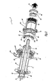
- the hub 2 comprises a hollow shaft 10 whose longitudinal axis X 10 is noted, this shaft 10 carries, at a first threaded end 12, a nut 14. At its threaded end 16 opposite the end 12 the shaft 10 carries a second nut 18.
- the nuts 14 and 18 allow the mounting of the hub 2 and the wheel to which it belongs on the not shown frame of a bicycle.
- axial and radial are defined with respect to the axis X 10 .
- an axial dimension is measured parallel to the axis X 10
- a radial dimension is measured in a radial direction relative to this axis.
- a hub body 20 is mounted around the shaft 10, with possibility of rotation, relative to the shaft 10, about the axis X 10 .
- Two ball bearings 22 and 24 are radially interposed between the shaft 10 and the body 20. These bearings are disposed at the axial ends 26 and 28 of the body 20. It should be noted that the large axial spacing between the bearings 22 and 24 provides very good stiffness and resistance to the hub and the wheel.
- the body 20 carries a ring 30 provided with an internal toothing 32 whose teeth are inclined.
- the ring 30 is screwed into an annular portion 21 of the body 20 which is provided with housings 211 for receiving the glued ends of certain spokes 4.
- a freewheel body 40 is disposed around a circular section cylindrical nozzle 23 formed by the body 20 and extending between the annular portion 21 and the end 28 of the body.
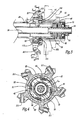
- the freewheel body 40 forms a support 42 in which are disposed four pawls 50 intended to interact with the toothing 32 to selectively fasten the bodies 20 and 40 when the hub 2 is in pedaling configuration where the freewheel body 40 is driving relative to the hub body 20 because the user exerts a driving force in rotation of the freewheel body, by means of a not shown chain.
- the pawls 50 thus allow a unidirectional rotation of the hub body 20 with respect to the freewheel body 40.
- the number of ratchets 50 may be different from four. In the example of the figures, they work here in pairs to reduce the snap-fit and are each loaded by a spring not shown.
- the body 40 is provided with external ribs 44 forming reliefs for rotationally fastening with a pinion cassette 60 shown solely on the figure 3 , in mixed lines, by the trace of its envelope.
- This pinion cassette is engaged with the unrepresented chain of the bicycle.
- a ring 46 disposed inside the body 40 forms a housing for receiving a ball bearing 48 interposed between the body 40 and the shaft 10.
- a threaded washer 70 is provided to close the body 40, the opposite of the support 42, while receiving the nut 18 tightened on the threaded end 16 of the shaft 10.
- the body 40 is provided with an internal radial groove 41 in which fifteen rolls 100 made of PEEK (polyether-ether-ketone) are held in position in the groove 41 by means of three cages 110 each carrying five rolls 100.
- PEEK polyether-ether-ketone
- each roll 100 is cylindrical, of circular section, centered on an axis X 100 and hollow, so that it defines an inner volume V 100 of cylindrical shape with circular section.
- Its nominal outside diameter D 100 . without stress, has a value of about 4.9 mm, while its radial thickness is about 0.65 mm and its axial length, parallel to the axis X 100 , about 3 mm.
- each roller 100 is elastically deformable under normal temperature conditions for use of the hub 2, that is to say for temperatures between -40 and + 60 °.
- Each cage 110 is formed of two flanges 112 and 114 which are disposed on either side of five rollers 100.
- Each flange 112 is provided with five projections 116 in the form of hollow sleeve, while each flange 114 is provided with five other projections 118 also in the form of hollow sleeve.
- Each sleeve 118 can penetrate inside a sleeve 116, the set of two sleeves engaged one inside the other being received in the interior volume V 100 of a roll 100.
- the flanges 112 and 114 may be considered clipped together with their projections 116 and 118 inside the rollers 100.
- the projections 116 and 118 together form shafts defining axes of rotation X 110 for the rollers 100.
- the axes X 110 correspond to the longitudinal axes of the projections 116 and 118, these axes being merged in the assembled configuration of the cages 110 and parallel to the axis X 10 in the mounted configuration of the freewheel
- the rollers 100 are mounted around the projections 118 with a radial clearance J 100 , which allows their deformation by radial crushing when necessary.
- the figure 10 shows that the cages 110 are flexible, in that they can be folded by folding their ends towards each other, as represented by the arrows F 1 in this figure.
- This facilitates the introduction of the rollers 100 in the groove 41. Indeed, it is possible to successively engage two cages 110 each equipped with five rollers 100 in the groove 41, then to come to bear against one against the other these two cages, as shown for the two cages visible on the left of the figure 10 .
- the ends of a third cage 110 can then be folded towards one another, as represented by the arrows F 1 , and then this cage can be engaged in the groove 41 before releasing its ends which then become lodged opposite the ends free of all formed two cages already in place in the groove 41. In doing so, the three cages 110 are positioned inside the groove 41, in such a way that they cooperate with each other to stay in position inside the groove 41.
- the three cages 110 thus together form a multipartite cage C and elastically deformable holding the series of fifteen rollers 100 in the groove 41.
- the material used for the cage C is a thermoplastic material, for example polyacetal.
- the number of cages 110 used is not necessarily three. It is possible to envisage a variant with a single cage which is deformed radially in a centripetal manner so as to be put in place in the groove 41.
- cages 110 are particularly advantageous, it is not mandatory. Indeed, one can design a free wheel hub 2 in which the rollers 100 are arranged individually in the groove 41, without use of cage. In this case, these rollers are lubricated and the viscosity of the oil used makes it possible to hold them in position in the groove 41, even when the body 40 is separated from the body 20.
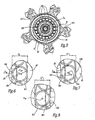
- Two operating configurations can be considered when the rollers 100 are in place in the groove 41.
- the hub body 20 In a first configuration corresponding to the freewheel mode operation of the hub 2, the hub body 20 must be able to rotate around the shaft 10 and the X axis 10 , while the freewheel body 40 remains fixed around of the shaft 10 and the X axis 10 .
- the rollers 100 together form a support bearing of the free wheel body 40 around the hub member 23. Indeed, these rollers 100 are able to roll against the bottom 411 of the groove 41 and against the outer radial surface 231 of the endpiece 23, so that they maintain the inner radial surface 421 of the support 42 radially at a distance from none of the surface 231.
- the distance between the bottom 411 and the surface 231 is equi-distributed around the axis X 10 .
- the clearance to the diameter existing between the inner radial surface 421 and the surface 231 is between 0.1 mm and 0.15 mm.
- the rollers 100 are arranged in the groove 100 while being slightly compressed since the radial distance d 1 between the bottom 411 and the surface 231 is slightly smaller than the nominal external diameter D 100 of the rollers 100.
- the distance d 1 is equal to 4.8 mm.
- the diameter D 100 is shown, while the roller 100 is slightly oval.
- the freewheel body 40 When the free wheel hub 2 is in the pedaling configuration, that is to say when a traction force is exerted in the upper part of the pinion cassette 60, the freewheel body 40 tends to turn in the sense of arrows F 3 to figures 4 and 5 , which has the effect of causing the catches 50 to engage with the toothing 32 of the ring 30, thereby securing the bodies 20 and 40 in rotation.
- the freewheel body 40 taking account of the force exerted by the chain on the cassette 60 and the action of the pawls, the freewheel body 40 tends to move radially in the direction of the tension of the chain relative to the hub body 20 and its endpiece 23, perpendicular to the axis X 10 .
- the localized crushing and reversible rollers 100 located above the X-axis 10 allows a firm support freewheel body 40 of the hub body 20 at the interface between the surfaces 421 and 231 , when the free wheel hub is in the pedaling configuration. This allows a torque transmission between the freewheel body 40, which is driving, and the hub body 20, which is driven.
- D 40 denotes the diameter of the surface 421, D 20 the diameter of the surface 231 and P 41 the radial depth of the groove 41 relative to the surface 421 that it borders.
- the diameter D 40 is slightly greater than the diameter D 20 .
- the respective values of the diameters D 20 and D 40 and the depth P 41 are chosen so that the rollers 100 are always slightly compressed radially, including in the configuration of the figure 8 , which guarantees their simultaneous support on the bottom 411 of the groove 41 and on the surface 231 in all configurations of use of the hub 2 and regardless of the angular position of a roll 100 about the axis X 10 .
- the fact that the rollers 100 are permanently slightly compressed makes it possible to catch the manufacturing tolerances.
- rollers 100 are permanently prestressed and it is possible to envisage an embodiment where these rollers are not prestressed in the configuration of the figure 8 .
- the ovalization of the rollers 100 in the configuration of the figure 6 is minimal, so that the bearing formed by all of these rollers performs its bearing function under a load generally less than 4 daN as conventionally encountered in the hubs in freewheel configuration under the action of the only tension of the two strands of chain generated by the chain tensioner of the rear derailleur not shown.
- the free wheel hub 2 of the figure 14 comprises a hub body 20 associated with a freewheel body 40, with the interposition of a first series of elastically deformable rollers 100 PEEK received in a groove 41 of the freewheel body 20, as in the first embodiment .
- no cage is provided for holding the rollers 100 in position, these being lubricated by means of an oil whose viscosity ensures their retention in the groove 41.
- a support 42 formed by the freewheel body 40 carries pawls 50 for unidirectionally locking in rotation between the bodies 20 and 40, in the pedaling configuration.
- 421 is the internal radial surface of the support 42.
- the outer radial surface 201 of the hub body 20 is provided with a groove 25 in which the rollers 100 are partially inserted, which contributes to the axial guidance of these rollers.
- the body 20 is bi-partite and comprises a main body 27 on which is attached by screwing a tip 23 which bears on a ball bearing 24 for the rotation of the hub body 20 relative to a central shaft 10 of the free wheel hub 2 which defines the axis of rotation X 10 of the hub.
- the groove 25 is formed at the end of the body 27 and laterally delimited by the tip 23 screwed onto this body.
- Another ball bearing 22 supports the hub body 20 with respect to the shaft 10, in the vicinity of the axial end of this body opposite the rolling bearing 24.
- the freewheel body 40 is positioned axially, along the axis X 10 of the shaft 10, by two shoulders but could also be positioned axially directly by a row of rollers or by the two rows of rollers, these the latter having with the body 40 contacts in opposition bilaterally.
- the body 40 is provided with an internal rib 45 whose internal radial surface 451 surrounds the outer radial surface 231 of the nozzle 23, axially substantially at the same level as the bearing 24.
- a second series of elastically deformable rollers PEEK 200 is disposed in a groove 29 formed in the nozzle 23, from its outer radial surface 231.
- the rib 45 extends axially to the level of the rollers 200.
- the rollers 200 are sized to support the internal radial surface 451 of the rib 45. They are coated with an oil whose viscosity allows to retain them in the groove 29.
- the rollers 100 and 200 operate generally like the rollers 100 of the first embodiment and can take a first configuration where they allow rotation between the bodies 20 and 40, forming, in the case where the hub is used freewheel, two bearings which maintain spaced apart radially from each other the surfaces 201 and 421, on the one hand, 451 and 231, on the other hand.
- the rollers 100 roll on the bottoms 411 and 251 of the grooves 41 and 25, while the rollers 200 roll on the bottom 291 of the groove 29 and on the surface 451.
- rollers 100 and 200 are, for some of them located at the rear of the X axis 10 , crushed, which allows contact between the bodies 20 and 40, respectively at the interface between the surfaces 201 and 421, on the one hand, 451 and 231, on the other hand.
- a double fastening of the bodies 20 and 40 in the pedal configuration is obtained, that is to say in the configuration where the rollers 100 and 200 are partly crushed by elastic deformation. Indeed, a contact takes place between the bodies 20 and 40 in the vicinity of the two ends of the tip 23, namely between the surfaces 201 and 421, on the one hand, and between the surfaces 231 and 451, on the other hand .
- this embodiment operates as the first and the rollers 100 and 200 are elastically deformable under the normal conditions of use of the hub 2.
- the positioning of the rollers 100 and 200 can be reversed.
- the rollers closest to the pawls 50 may be housed mainly in a groove in the hub body 20, while the rollers closest to the end 16 of the shaft 2 are housed in a groove of the wheel body.
- the elastically deformable rollers may be arranged in grooves provided both on the hub body 20 or both on the freewheel body 40.
- a single series of elastically deformable rollers may be provided, as in the first embodiment, this series being received in a groove on the hub body 20.
- the bodies 20 and 40 may be aluminum, which gives a great lightness to the hub 2, as well as an attractive cost, unlike a hub where parts of these bodies should be made of high strength steel, as would be the case if needle bearings were used.
- the rollers 100 and possibly 200 may be manufactured in different synthetic materials other than PEEK, in particular polyacetal or polyurethane. They can also be made of metal, in particular aluminum which, depending on the radial thickness selected for these rollers, also has a capacity to deform elastically under the intended conditions of use.
- the rollers may also be made of magnesium or alloy based on aluminum or magnesium.
- the rollers 100 and possibly 200 may also be solid, particularly in the case of polyurethane rollers.
- the cage or cages are adapted or eliminated, as mentioned above with reference to the embodiments where it is the viscosity of the oil that holds the rollers in the groove.
- the PEEK is particularly suitable for the production of rollers 100 and possibly 200 to the extent that, up to 140 ° C, it does not have relaxation, while its modulus of elasticity is the order of 4500 MPa and that its elastic limit is of the order of 200 MPa.
- the polyacetal also has satisfactory properties, with an elasticity model of about 2700 MPa and an elastic limit of about 40 MPa. However, permanent deformations can be obtained at temperatures above 60 °. Other materials may however be used to make the rolls 100, as mentioned above.
- PEEK or other synthetic material is particularly advantageous in terms of weight. Indeed, the density of PEEK or other synthetic materials is low.
- fifteen hollow rollers 100 with a nominal diameter D 100 equal to 4.9 mm have a total weight of 0.25 grams, the cages 110 having a weight of the same order of magnitude, which is considerably less than the weight of a steel bearing of the same size which is of the order of 20 grams.
- the rolling tracks of the deformable rollers can be, optionally, defined on the surface 231 or 451 of a portion of one of the bodies 20 or 40 or at the bottom of a groove such as the groove 25. It can be, at choice, use or not roll holding cages 100 and 200 in all embodiments.
- the ball bearings 22, 24 and 48 can be replaced by other bearings with non-deformable rolling bodies, for example roller or needle bearings.
Landscapes
- Engineering & Computer Science (AREA)
- Mechanical Engineering (AREA)
- General Engineering & Computer Science (AREA)
- Rolling Contact Bearings (AREA)
- Rolls And Other Rotary Bodies (AREA)
Applications Claiming Priority (1)
| Application Number | Priority Date | Filing Date | Title |
|---|---|---|---|
| FR0807132A FR2940382B1 (fr) | 2008-12-18 | 2008-12-18 | Moyeu roue-libre et roue de cycle equipee d'un tel moyeu |
Publications (2)
| Publication Number | Publication Date |
|---|---|
| EP2199636A1 true EP2199636A1 (de) | 2010-06-23 |
| EP2199636B1 EP2199636B1 (de) | 2012-07-04 |
Family
ID=40846233
Family Applications (1)
| Application Number | Title | Priority Date | Filing Date |
|---|---|---|---|
| EP20090014551 Not-in-force EP2199636B1 (de) | 2008-12-18 | 2009-11-23 | Freilaufnabe und Rad eines Fahrrads mit derselben |
Country Status (3)
| Country | Link |
|---|---|
| EP (1) | EP2199636B1 (de) |
| CN (1) | CN101774332B (de) |
| FR (1) | FR2940382B1 (de) |
Cited By (1)
| Publication number | Priority date | Publication date | Assignee | Title |
|---|---|---|---|---|
| US20240308267A1 (en) * | 2021-01-27 | 2024-09-19 | Kubus Corporate Holdings B.V. | Cycle Hub Assembly |
Families Citing this family (2)
| Publication number | Priority date | Publication date | Assignee | Title |
|---|---|---|---|---|
| CN110225833A (zh) * | 2016-12-22 | 2019-09-10 | 米其林集团总公司 | 非充气车轮和轮毂 |
| CN109017145B (zh) * | 2018-09-28 | 2023-06-13 | 南京工业职业技术学院 | 一种液压调节滚子方向的麦克纳姆轮 |
Citations (3)
| Publication number | Priority date | Publication date | Assignee | Title |
|---|---|---|---|---|
| FR2678991A1 (fr) | 1991-07-09 | 1993-01-15 | Bg Innovations | Moyeu a roue libre pour cycles. |
| FR2734617A1 (fr) | 1995-05-22 | 1996-11-29 | Fichtel & Sachs Ag | Moyeu a roue libre pour cycle |
| FR2894310A1 (fr) | 2005-12-07 | 2007-06-08 | Salomon Sa | Moyeu roue libre |
Family Cites Families (2)
| Publication number | Priority date | Publication date | Assignee | Title |
|---|---|---|---|---|
| CN1079699A (zh) * | 1991-11-26 | 1993-12-22 | 海波科学公司 | 改进的自行车轮毂 |
| JP3832909B2 (ja) * | 1996-10-04 | 2006-10-11 | 株式会社シマノ | 自転車用ブレーキ |
-
2008
- 2008-12-18 FR FR0807132A patent/FR2940382B1/fr not_active Expired - Fee Related
-
2009
- 2009-11-23 EP EP20090014551 patent/EP2199636B1/de not_active Not-in-force
- 2009-12-17 CN CN200910253747.7A patent/CN101774332B/zh not_active Expired - Fee Related
Patent Citations (3)
| Publication number | Priority date | Publication date | Assignee | Title |
|---|---|---|---|---|
| FR2678991A1 (fr) | 1991-07-09 | 1993-01-15 | Bg Innovations | Moyeu a roue libre pour cycles. |
| FR2734617A1 (fr) | 1995-05-22 | 1996-11-29 | Fichtel & Sachs Ag | Moyeu a roue libre pour cycle |
| FR2894310A1 (fr) | 2005-12-07 | 2007-06-08 | Salomon Sa | Moyeu roue libre |
Cited By (1)
| Publication number | Priority date | Publication date | Assignee | Title |
|---|---|---|---|---|
| US20240308267A1 (en) * | 2021-01-27 | 2024-09-19 | Kubus Corporate Holdings B.V. | Cycle Hub Assembly |
Also Published As
| Publication number | Publication date |
|---|---|
| FR2940382A1 (fr) | 2010-06-25 |
| FR2940382B1 (fr) | 2011-02-11 |
| CN101774332B (zh) | 2014-02-26 |
| EP2199636B1 (de) | 2012-07-04 |
| CN101774332A (zh) | 2010-07-14 |
Similar Documents
| Publication | Publication Date | Title |
|---|---|---|
| EP0202968B1 (de) | Homokinetisches ausziehbares Kreuzgelenk, insbesondere für Fahrzeug-Schräggetriebe | |
| EP2177373B1 (de) | Radlager-Montagevorrichtung und Fahrradnabe, die eine solche Vorrichtung einschließt | |
| WO2012156613A1 (fr) | Dispositif de changement de vitesse pour velo | |
| FR3091517A1 (fr) | Dispositif d’assistance électrique pour vélo | |
| EP1865206A2 (de) | Keilriementriebwerk | |
| EP3908511A2 (de) | Untersetzungsgetriebe | |
| EP2199198B1 (de) | Getriebeeinheit für ein Fahrrad | |
| EP2199636B1 (de) | Freilaufnabe und Rad eines Fahrrads mit derselben | |
| FR2917332A1 (fr) | Roue comprenant une jante, un moyeu, et un dispositif de raccordement de la jante au moyeu | |
| EP3063418B1 (de) | Verbindungsanordnung mit einem haltering für eine welle verfahren zur montage solch einer verbindungsanordnung | |
| EP0522983A1 (de) | Fahrradnabe mit Freilauf | |
| FR3039458A1 (fr) | Moyeu pour roue de cycle | |
| EP0191710A2 (de) | Fahrrad | |
| WO2016174342A1 (fr) | Procédé de réalisation d'un dispositif d'amortissement d'oscillations de torsion | |
| FR2534335A1 (fr) | Dispositif d'entrainement a roue a rochet et a cliquets, en particulier pour moyeu a roue libre de bicyclette | |
| EP1626891A1 (de) | Verfahren zur befestigung eines fahrradrades an einem rahmen | |
| EP0983186A1 (de) | Kraftübersetzungsgetriebe für fahrrad und fahrrad | |
| EP0677404B1 (de) | Antriebsachse für Höheneinstellung der Antriebsräder einer selbstangetriebenen Maschine mit demontierbaren Lagern und Maschine mit solcher Achse | |
| EP2283242A2 (de) | Wälzlager mit kugelförmigen separatoren | |
| FR2700372A1 (fr) | Perfectionnement pour roue libre. | |
| EP1796797A1 (de) | Rollschuhrad mit recycelbarer nabe mit einem kugellager | |
| FR2832672A1 (fr) | Moyeu de roue et roue ayant un tel moyeu | |
| EP1798058A2 (de) | Radnabe und Rad mit solcher Nabe | |
| FR3018328A3 (fr) | Differentiel pour vehicule automobile avec dispositif de maintien en position de l'axe porte-satellite | |
| FR3147733A1 (fr) | Moyeu arriere a roue libre pour cycle |
Legal Events
| Date | Code | Title | Description |
|---|---|---|---|
| PUAI | Public reference made under article 153(3) epc to a published international application that has entered the european phase |
Free format text: ORIGINAL CODE: 0009012 |
|
| AK | Designated contracting states |
Kind code of ref document: A1 Designated state(s): AT BE BG CH CY CZ DE DK EE ES FI FR GB GR HR HU IE IS IT LI LT LU LV MC MK MT NL NO PL PT RO SE SI SK SM TR |
|
| AX | Request for extension of the european patent |
Extension state: AL BA RS |
|
| 17P | Request for examination filed |
Effective date: 20101006 |
|
| RAP1 | Party data changed (applicant data changed or rights of an application transferred) |
Owner name: MAVIC S.A.S. |
|
| GRAP | Despatch of communication of intention to grant a patent |
Free format text: ORIGINAL CODE: EPIDOSNIGR1 |
|
| RIC1 | Information provided on ipc code assigned before grant |
Ipc: F16C 27/04 20060101ALN20111205BHEP Ipc: F16D 41/30 20060101AFI20111205BHEP Ipc: B60B 27/02 20060101ALI20111205BHEP |
|
| GRAS | Grant fee paid |
Free format text: ORIGINAL CODE: EPIDOSNIGR3 |
|
| GRAA | (expected) grant |
Free format text: ORIGINAL CODE: 0009210 |
|
| AK | Designated contracting states |
Kind code of ref document: B1 Designated state(s): AT BE BG CH CY CZ DE DK EE ES FI FR GB GR HR HU IE IS IT LI LT LU LV MC MK MT NL NO PL PT RO SE SI SK SM TR |
|
| REG | Reference to a national code |
Ref country code: GB Ref legal event code: FG4D Free format text: NOT ENGLISH |
|
| REG | Reference to a national code |
Ref country code: CH Ref legal event code: EP |
|
| REG | Reference to a national code |
Ref country code: AT Ref legal event code: REF Ref document number: 565296 Country of ref document: AT Kind code of ref document: T Effective date: 20120715 |
|
| REG | Reference to a national code |
Ref country code: IE Ref legal event code: FG4D Free format text: LANGUAGE OF EP DOCUMENT: FRENCH |
|
| REG | Reference to a national code |
Ref country code: DE Ref legal event code: R096 Ref document number: 602009007963 Country of ref document: DE Effective date: 20120830 |
|
| REG | Reference to a national code |
Ref country code: AT Ref legal event code: MK05 Ref document number: 565296 Country of ref document: AT Kind code of ref document: T Effective date: 20120704 |
|
| REG | Reference to a national code |
Ref country code: NL Ref legal event code: VDEP Effective date: 20120704 |
|
| PG25 | Lapsed in a contracting state [announced via postgrant information from national office to epo] |
Ref country code: SI Free format text: LAPSE BECAUSE OF FAILURE TO SUBMIT A TRANSLATION OF THE DESCRIPTION OR TO PAY THE FEE WITHIN THE PRESCRIBED TIME-LIMIT Effective date: 20120704 |
|
| REG | Reference to a national code |
Ref country code: LT Ref legal event code: MG4D Effective date: 20120725 |
|
| PG25 | Lapsed in a contracting state [announced via postgrant information from national office to epo] |
Ref country code: LT Free format text: LAPSE BECAUSE OF FAILURE TO SUBMIT A TRANSLATION OF THE DESCRIPTION OR TO PAY THE FEE WITHIN THE PRESCRIBED TIME-LIMIT Effective date: 20120704 Ref country code: CY Free format text: LAPSE BECAUSE OF FAILURE TO SUBMIT A TRANSLATION OF THE DESCRIPTION OR TO PAY THE FEE WITHIN THE PRESCRIBED TIME-LIMIT Effective date: 20120704 Ref country code: FI Free format text: LAPSE BECAUSE OF FAILURE TO SUBMIT A TRANSLATION OF THE DESCRIPTION OR TO PAY THE FEE WITHIN THE PRESCRIBED TIME-LIMIT Effective date: 20120704 Ref country code: AT Free format text: LAPSE BECAUSE OF FAILURE TO SUBMIT A TRANSLATION OF THE DESCRIPTION OR TO PAY THE FEE WITHIN THE PRESCRIBED TIME-LIMIT Effective date: 20120704 Ref country code: HR Free format text: LAPSE BECAUSE OF FAILURE TO SUBMIT A TRANSLATION OF THE DESCRIPTION OR TO PAY THE FEE WITHIN THE PRESCRIBED TIME-LIMIT Effective date: 20120704 Ref country code: IS Free format text: LAPSE BECAUSE OF FAILURE TO SUBMIT A TRANSLATION OF THE DESCRIPTION OR TO PAY THE FEE WITHIN THE PRESCRIBED TIME-LIMIT Effective date: 20121104 Ref country code: NO Free format text: LAPSE BECAUSE OF FAILURE TO SUBMIT A TRANSLATION OF THE DESCRIPTION OR TO PAY THE FEE WITHIN THE PRESCRIBED TIME-LIMIT Effective date: 20121004 |
|
| PG25 | Lapsed in a contracting state [announced via postgrant information from national office to epo] |
Ref country code: LV Free format text: LAPSE BECAUSE OF FAILURE TO SUBMIT A TRANSLATION OF THE DESCRIPTION OR TO PAY THE FEE WITHIN THE PRESCRIBED TIME-LIMIT Effective date: 20120704 Ref country code: PL Free format text: LAPSE BECAUSE OF FAILURE TO SUBMIT A TRANSLATION OF THE DESCRIPTION OR TO PAY THE FEE WITHIN THE PRESCRIBED TIME-LIMIT Effective date: 20120704 Ref country code: SE Free format text: LAPSE BECAUSE OF FAILURE TO SUBMIT A TRANSLATION OF THE DESCRIPTION OR TO PAY THE FEE WITHIN THE PRESCRIBED TIME-LIMIT Effective date: 20120704 Ref country code: PT Free format text: LAPSE BECAUSE OF FAILURE TO SUBMIT A TRANSLATION OF THE DESCRIPTION OR TO PAY THE FEE WITHIN THE PRESCRIBED TIME-LIMIT Effective date: 20121105 Ref country code: GR Free format text: LAPSE BECAUSE OF FAILURE TO SUBMIT A TRANSLATION OF THE DESCRIPTION OR TO PAY THE FEE WITHIN THE PRESCRIBED TIME-LIMIT Effective date: 20121005 |
|
| PGFP | Annual fee paid to national office [announced via postgrant information from national office to epo] |
Ref country code: IT Payment date: 20121130 Year of fee payment: 4 |
|
| PG25 | Lapsed in a contracting state [announced via postgrant information from national office to epo] |
Ref country code: NL Free format text: LAPSE BECAUSE OF FAILURE TO SUBMIT A TRANSLATION OF THE DESCRIPTION OR TO PAY THE FEE WITHIN THE PRESCRIBED TIME-LIMIT Effective date: 20120704 |
|
| PG25 | Lapsed in a contracting state [announced via postgrant information from national office to epo] |
Ref country code: RO Free format text: LAPSE BECAUSE OF FAILURE TO SUBMIT A TRANSLATION OF THE DESCRIPTION OR TO PAY THE FEE WITHIN THE PRESCRIBED TIME-LIMIT Effective date: 20120704 Ref country code: DK Free format text: LAPSE BECAUSE OF FAILURE TO SUBMIT A TRANSLATION OF THE DESCRIPTION OR TO PAY THE FEE WITHIN THE PRESCRIBED TIME-LIMIT Effective date: 20120704 Ref country code: ES Free format text: LAPSE BECAUSE OF FAILURE TO SUBMIT A TRANSLATION OF THE DESCRIPTION OR TO PAY THE FEE WITHIN THE PRESCRIBED TIME-LIMIT Effective date: 20121015 Ref country code: EE Free format text: LAPSE BECAUSE OF FAILURE TO SUBMIT A TRANSLATION OF THE DESCRIPTION OR TO PAY THE FEE WITHIN THE PRESCRIBED TIME-LIMIT Effective date: 20120704 Ref country code: CZ Free format text: LAPSE BECAUSE OF FAILURE TO SUBMIT A TRANSLATION OF THE DESCRIPTION OR TO PAY THE FEE WITHIN THE PRESCRIBED TIME-LIMIT Effective date: 20120704 |
|
| PLBE | No opposition filed within time limit |
Free format text: ORIGINAL CODE: 0009261 |
|
| STAA | Information on the status of an ep patent application or granted ep patent |
Free format text: STATUS: NO OPPOSITION FILED WITHIN TIME LIMIT |
|
| BERE | Be: lapsed |
Owner name: MAVIC S.A.S. Effective date: 20121130 |
|
| PG25 | Lapsed in a contracting state [announced via postgrant information from national office to epo] |
Ref country code: SK Free format text: LAPSE BECAUSE OF FAILURE TO SUBMIT A TRANSLATION OF THE DESCRIPTION OR TO PAY THE FEE WITHIN THE PRESCRIBED TIME-LIMIT Effective date: 20120704 |
|
| 26N | No opposition filed |
Effective date: 20130405 |
|
| PG25 | Lapsed in a contracting state [announced via postgrant information from national office to epo] |
Ref country code: BG Free format text: LAPSE BECAUSE OF FAILURE TO SUBMIT A TRANSLATION OF THE DESCRIPTION OR TO PAY THE FEE WITHIN THE PRESCRIBED TIME-LIMIT Effective date: 20121004 |
|
| REG | Reference to a national code |
Ref country code: DE Ref legal event code: R097 Ref document number: 602009007963 Country of ref document: DE Effective date: 20130405 |
|
| REG | Reference to a national code |
Ref country code: IE Ref legal event code: MM4A |
|
| PG25 | Lapsed in a contracting state [announced via postgrant information from national office to epo] |
Ref country code: BE Free format text: LAPSE BECAUSE OF NON-PAYMENT OF DUE FEES Effective date: 20121130 |
|
| PG25 | Lapsed in a contracting state [announced via postgrant information from national office to epo] |
Ref country code: IE Free format text: LAPSE BECAUSE OF NON-PAYMENT OF DUE FEES Effective date: 20121123 |
|
| PG25 | Lapsed in a contracting state [announced via postgrant information from national office to epo] |
Ref country code: MT Free format text: LAPSE BECAUSE OF FAILURE TO SUBMIT A TRANSLATION OF THE DESCRIPTION OR TO PAY THE FEE WITHIN THE PRESCRIBED TIME-LIMIT Effective date: 20120704 |
|
| PG25 | Lapsed in a contracting state [announced via postgrant information from national office to epo] |
Ref country code: TR Free format text: LAPSE BECAUSE OF FAILURE TO SUBMIT A TRANSLATION OF THE DESCRIPTION OR TO PAY THE FEE WITHIN THE PRESCRIBED TIME-LIMIT Effective date: 20120704 Ref country code: MC Free format text: LAPSE BECAUSE OF NON-PAYMENT OF DUE FEES Effective date: 20121130 |
|
| PG25 | Lapsed in a contracting state [announced via postgrant information from national office to epo] |
Ref country code: LU Free format text: LAPSE BECAUSE OF NON-PAYMENT OF DUE FEES Effective date: 20121123 Ref country code: SM Free format text: LAPSE BECAUSE OF FAILURE TO SUBMIT A TRANSLATION OF THE DESCRIPTION OR TO PAY THE FEE WITHIN THE PRESCRIBED TIME-LIMIT Effective date: 20120704 |
|
| REG | Reference to a national code |
Ref country code: CH Ref legal event code: PL |
|
| GBPC | Gb: european patent ceased through non-payment of renewal fee |
Effective date: 20131123 |
|
| PG25 | Lapsed in a contracting state [announced via postgrant information from national office to epo] |
Ref country code: LI Free format text: LAPSE BECAUSE OF NON-PAYMENT OF DUE FEES Effective date: 20131130 Ref country code: HU Free format text: LAPSE BECAUSE OF FAILURE TO SUBMIT A TRANSLATION OF THE DESCRIPTION OR TO PAY THE FEE WITHIN THE PRESCRIBED TIME-LIMIT Effective date: 20091123 Ref country code: CH Free format text: LAPSE BECAUSE OF NON-PAYMENT OF DUE FEES Effective date: 20131130 |
|
| PG25 | Lapsed in a contracting state [announced via postgrant information from national office to epo] |
Ref country code: IT Free format text: LAPSE BECAUSE OF NON-PAYMENT OF DUE FEES Effective date: 20131123 |
|
| PG25 | Lapsed in a contracting state [announced via postgrant information from national office to epo] |
Ref country code: GB Free format text: LAPSE BECAUSE OF NON-PAYMENT OF DUE FEES Effective date: 20131123 |
|
| PG25 | Lapsed in a contracting state [announced via postgrant information from national office to epo] |
Ref country code: MK Free format text: LAPSE BECAUSE OF FAILURE TO SUBMIT A TRANSLATION OF THE DESCRIPTION OR TO PAY THE FEE WITHIN THE PRESCRIBED TIME-LIMIT Effective date: 20120704 |
|
| REG | Reference to a national code |
Ref country code: FR Ref legal event code: PLFP Year of fee payment: 7 |
|
| REG | Reference to a national code |
Ref country code: FR Ref legal event code: PLFP Year of fee payment: 8 |
|
| REG | Reference to a national code |
Ref country code: FR Ref legal event code: PLFP Year of fee payment: 9 |
|
| REG | Reference to a national code |
Ref country code: FR Ref legal event code: PLFP Year of fee payment: 10 |
|
| PGFP | Annual fee paid to national office [announced via postgrant information from national office to epo] |
Ref country code: DE Payment date: 20181113 Year of fee payment: 10 |
|
| PGFP | Annual fee paid to national office [announced via postgrant information from national office to epo] |
Ref country code: FR Payment date: 20181011 Year of fee payment: 10 |
|
| REG | Reference to a national code |
Ref country code: DE Ref legal event code: R119 Ref document number: 602009007963 Country of ref document: DE |
|
| PG25 | Lapsed in a contracting state [announced via postgrant information from national office to epo] |
Ref country code: DE Free format text: LAPSE BECAUSE OF NON-PAYMENT OF DUE FEES Effective date: 20200603 Ref country code: FR Free format text: LAPSE BECAUSE OF NON-PAYMENT OF DUE FEES Effective date: 20191130 |