EP2199644A2 - Engine balancer - Google Patents
Engine balancer Download PDFInfo
- Publication number
- EP2199644A2 EP2199644A2 EP09179841A EP09179841A EP2199644A2 EP 2199644 A2 EP2199644 A2 EP 2199644A2 EP 09179841 A EP09179841 A EP 09179841A EP 09179841 A EP09179841 A EP 09179841A EP 2199644 A2 EP2199644 A2 EP 2199644A2
- Authority
- EP
- European Patent Office
- Prior art keywords
- balancer
- housing
- engine
- bearing
- pair
- Prior art date
- Legal status (The legal status is an assumption and is not a legal conclusion. Google has not performed a legal analysis and makes no representation as to the accuracy of the status listed.)
- Withdrawn
Links
- 238000005096 rolling process Methods 0.000 claims abstract description 103
- 230000000149 penetrating effect Effects 0.000 claims description 5
- 239000003921 oil Substances 0.000 description 93
- 239000010687 lubricating oil Substances 0.000 description 38
- 125000006850 spacer group Chemical group 0.000 description 17
- 238000003780 insertion Methods 0.000 description 12
- 230000037431 insertion Effects 0.000 description 12
- 238000005461 lubrication Methods 0.000 description 12
- 238000005452 bending Methods 0.000 description 11
- 230000005484 gravity Effects 0.000 description 10
- 229910052751 metal Inorganic materials 0.000 description 8
- 239000002184 metal Substances 0.000 description 8
- 230000033001 locomotion Effects 0.000 description 7
- 230000005540 biological transmission Effects 0.000 description 5
- 239000000446 fuel Substances 0.000 description 5
- 230000001360 synchronised effect Effects 0.000 description 4
- 229910052782 aluminium Inorganic materials 0.000 description 2
- XAGFODPZIPBFFR-UHFFFAOYSA-N aluminium Chemical compound [Al] XAGFODPZIPBFFR-UHFFFAOYSA-N 0.000 description 2
- 238000007654 immersion Methods 0.000 description 2
- 230000001050 lubricating effect Effects 0.000 description 2
- 230000007246 mechanism Effects 0.000 description 2
- 238000000034 method Methods 0.000 description 2
- 230000003014 reinforcing effect Effects 0.000 description 2
- 229910000831 Steel Inorganic materials 0.000 description 1
- 238000005299 abrasion Methods 0.000 description 1
- 230000002411 adverse Effects 0.000 description 1
- 238000005266 casting Methods 0.000 description 1
- 238000001816 cooling Methods 0.000 description 1
- 238000005520 cutting process Methods 0.000 description 1
- 238000009826 distribution Methods 0.000 description 1
- 230000001747 exhibiting effect Effects 0.000 description 1
- 239000000463 material Substances 0.000 description 1
- 239000007769 metal material Substances 0.000 description 1
- 238000012986 modification Methods 0.000 description 1
- 230000004048 modification Effects 0.000 description 1
- 230000002093 peripheral effect Effects 0.000 description 1
- 230000008569 process Effects 0.000 description 1
- 230000009467 reduction Effects 0.000 description 1
- 239000010959 steel Substances 0.000 description 1
Images








Classifications
-
- F—MECHANICAL ENGINEERING; LIGHTING; HEATING; WEAPONS; BLASTING
- F16—ENGINEERING ELEMENTS AND UNITS; GENERAL MEASURES FOR PRODUCING AND MAINTAINING EFFECTIVE FUNCTIONING OF MACHINES OR INSTALLATIONS; THERMAL INSULATION IN GENERAL
- F16F—SPRINGS; SHOCK-ABSORBERS; MEANS FOR DAMPING VIBRATION
- F16F15/00—Suppression of vibrations in systems; Means or arrangements for avoiding or reducing out-of-balance forces, e.g. due to motion
- F16F15/22—Compensation of inertia forces
- F16F15/26—Compensation of inertia forces of crankshaft systems using solid masses, other than the ordinary pistons, moving with the system, i.e. masses connected through a kinematic mechanism or gear system
- F16F15/264—Rotating balancer shafts
- F16F15/267—Rotating balancer shafts characterised by bearing support of balancer shafts; Lubrication arrangements
-
- F—MECHANICAL ENGINEERING; LIGHTING; HEATING; WEAPONS; BLASTING
- F16—ENGINEERING ELEMENTS AND UNITS; GENERAL MEASURES FOR PRODUCING AND MAINTAINING EFFECTIVE FUNCTIONING OF MACHINES OR INSTALLATIONS; THERMAL INSULATION IN GENERAL
- F16F—SPRINGS; SHOCK-ABSORBERS; MEANS FOR DAMPING VIBRATION
- F16F2226/00—Manufacturing; Treatments
- F16F2226/04—Assembly or fixing methods; methods to form or fashion parts
-
- F—MECHANICAL ENGINEERING; LIGHTING; HEATING; WEAPONS; BLASTING
- F16—ENGINEERING ELEMENTS AND UNITS; GENERAL MEASURES FOR PRODUCING AND MAINTAINING EFFECTIVE FUNCTIONING OF MACHINES OR INSTALLATIONS; THERMAL INSULATION IN GENERAL
- F16F—SPRINGS; SHOCK-ABSORBERS; MEANS FOR DAMPING VIBRATION
- F16F2230/00—Purpose; Design features
- F16F2230/06—Fluid filling or discharging
Definitions
- the present disclosure relates to engine balancers provided in oil pans at the bottoms of engines and configured to reduce vibration and noise of the engines.
- a pair of balancer shafts having weight parts is supported by a housing with metal bearings interposed therebetween, and one of the balancer shafts receives power from a crankshaft to rotate in synchronization with the other balancer shaft through engaging gears engaged with each other, thereby canceling vibration due to rotational imbalance of the crankshaft caused by eccentric rotation of the weight parts.
- the balancer shafts always rotate at high speed together with the crankshaft, and thus the metal bearings for supporting the balancer shafts are lubricated with lubricating oil supplied from the outside.
- a balancer in which a housing is divided into upper and lower cases having half-circle shaped recess portions, and a hole formed by attaching these recess portions together forms a metal bearing, was proposed.
- a recess groove is formed at a facing surface between the upper and lower cases, and these upper and lower cases are brought into contact with each other to form a lubricating oil passage for supplying lubricating oil to the metal bearing.
- the housing is often formed by casting, the minimum thickness of the housing needs to be kept. For this reason, it is difficult to drastically reduce the thickness of the upper wall of the housing.
- the top of a housing body of a balancer housing located close to a crankshaft or a connecting rod has an aperture, and this aperture is covered with a cover member thinner than the housing body so that a drop of lubricating oil into the balancer housing is reduced and that the height of the balancer housing is reduced to locate the shaft axes of the balancer shafts at a higher level, thereby reducing immersion of rolling bearings in oil.
- the balancer housing includes a pair of front and rear bearing walls disposed in the fore and aft direction of the engine, and having a pair of left and right bearing holes respectively penetrating the pair of front and rear bearing walls and supporting the pair of balancer shafts with rolling bearings interposed therebetween, and a housing body located between the pair of front and rear bearing walls.
- the bearing walls of the balancer housing are attached to bearing walls for supporting the crankshaft provided in the engine.
- the housing body has an aperture at a top thereof. The aperture is covered with a plate-shaped cover member thinner than a member forming the housing body.
- the pair of balancer shafts is supported by a pair of front and rear bearing holes with rolling bearings interposed therebetween. Accordingly, as compared to the case of employing metal bearings, friction between the balancer shafts and the bearings can be reduced, thereby reducing fuel consumption.
- the bearing walls of the balancer housing are attached to the bearing walls for supporting the crankshaft provided in the engine, the crankshaft rotates above the housing body located between these bearing walls.
- the housing body has an aperture at the top thereof, and the aperture is covered with the cover member thinner than a member forming the housing body. Accordingly, as compared to a structure in which the balancer housing has a thick upper wall, the height of the balancer housing can be reduced such that the shaft axes of the balancer shafts can be located at a higher level. As a result, the rolling bearings are less likely to be immersed in oil.
- the aperture of the housing body is covered with the cover member, it is possible to reduce an unintentional supply of lubricating oil which has dropped from, for example, the crankshaft to the rolling bearings.
- the pair of balancer shafts includes balancer weight parts provided between the pair of front and rear bearing walls and engaging gears engaged with each other, and is inserted through an opening formed at a first side, in the fore and aft direction of the engine, of the balancer housing to be placed in the balancer housing, and an outer diameter of rotational path of each of the balancer weight parts is smaller than an inner diameter of an outer race of the rolling bearing of one of the pair of front and rear bearing walls located at the first side in the fore and aft direction of the engine, and is larger than an outer diameter of an inner race of the rolling bearing of the other bearing wall.
- the outer diameter of rotational path of the balancer weight parts is smaller than the inner diameter of outer race of the rolling bearing of one of the pair of front and rear bearing walls provided at the first side in the fore and aft direction of the engine, and is larger than the outer diameter of the inner race of the rolling bearing of the bearing wall at the second side in the fore and aft direction of the engine.
- the balancer shafts can be smoothly inserted through the end of the balancer housing at the first side in the fore and aft direction of the engine even in a case where the balancer shafts are inserted in the balancer housing with, for example, the inner race press fitted with the balancer shafts and the outer race press fitted with the balancer housing.
- reducing the outer diameter of rotational path of the balancer weight parts can achieve compact size of the balancer housing accordingly.
- a joint between a pair of balancer shafts needs to be tightened with bolts in order to prevent both cases from opening under hydraulic pressure.
- the distance between the pair of balancer shafts needs to be kept large.
- the balancer shafts are inserted through the end of the balancer housing at a first side, in the fore and aft direction of the engine, of the balancer housing. Accordingly, unlike conventional balancers, the balancer housing of this disclosure does not need to be split vertically. Therefore, it is unnecessary to increase the distance between the pair of balancer shafts, and the engaging gears provided for the balancer shafts can be made small, thereby achieving compact size of the balancer housing for housing the balancer shafts. As a result, immersion of the rolling bearings in oil can be further reduced.
- the cover member extends along an outer periphery of rotational path of each of the balancer weight parts in cross section.
- the cover member has a recess at, for example, an intermediate portion thereof in the lateral direction such that the cover member partially enters the housing.
- the shaft axes of the balancer shafts in the balancer housing can be located at a higher level.
- the engaging gears are closer to the first side in the fore and aft direction of the engine, than one of the pair of front and rear bearing walls located at the first side in the fore and aft direction of the engine.
- the engaging gears having an outer diameter larger than that of the balancer weight parts are located at the side opposite the side through which the balancer shafts are inserted. Accordingly, these engaging gears do not need to be inserted into the bearing holes formed through the pair of front and rear bearing walls. As a result, the bearing holes do not need to be larger, thereby achieving more compact size of the balancer housing.
- the cover member extends laterally outwardly beyond both ends, in the lateral direction of the engine, of the aperture, and is adjacent to the housing body with a gap interposed therebetween in the vertical direction of the engine.
- lubricating oil used for lubricating the rolling bearings is accumulated in the housing body, and the accumulated lubricating oil is swept by the balancer weight parts which provide synchronous rotation.
- the cover member is adjacent to the housing body with a gap interposed therebetween in the vertical direction of the engine.
- lubricating oil swept by the balancer weight parts passes through the gap.
- the cover member extends laterally outwardly beyond both ends, in the lateral direction of the engine, of the aperture. Accordingly, the lubricating oil that has passed through the gap is easily guided by the cover member to be drained to outside the housing body.
- mounting eyes project from tops of the pair of bearing walls of the balancer housing, the pair of bearing walls of the balancer housing is attached to the bearing walls for supporting the crankshaft with the mounting eyes interposed therebetween, and the cover member is located below tops of the mounting eyes in the vertical direction of the engine.
- the cover member is located below the tops of the mounting eyes in the vertical direction of the engine. Accordingly, even when the mounting eyes have a small projection length, it is possible to easily ensure a sufficient distance between the cover member and a connecting rod.
- the pair of bearing walls of the balancer housing is attached to the bearing walls for the supporting crankshaft sandwiching two adjacent cylinders in the fore and aft direction of the engine.
- the aperture of the housing body is formed across two cylinders of the engine, and thus the length of the balancer weight parts in the fore and aft direction of the engine can be increased. Accordingly, vibration due to rotational imbalance of the crankshaft can be canceled, without the necessity for increasing the length of the balancer weight parts in the radial direction of the shaft. As a result, reduction in the width and height of the balancer housing can be further ensured.
- the housing body has an aperture at the top thereof, and the aperture is covered with the cover member thinner than a member forming the housing body.
- FIG. 1 is a view schematically illustrating a main portion of an inline four-cylinder engine including a balancer 5 according to an example embodiment when viewed from the front side of a body 1 of the engine.
- an oil pan 3 is coupled to the bottom surface of a cylinder block 11 through a lower block 21.
- This oil pan 3 houses the balancer 5 coupled to the bottom surface of the lower block 21 and an oil pump (not shown).
- the engine body 1 is mounted on a vehicle, while being inclined about 10° with respect to a vertical line S shown in FIG. 1 . Accordingly, oil stored in the oil pan 3 occupies approximately the lower half of the oil pan 3 with the level surface L thereof inclined about 10° with respect to the joint surface between the oil pan 3 and the lower block 21.
- This transmission mechanism includes: a driving sprocket 19 attached to the tip of the crankshaft 9; a driven sprocket 35 attached to the tip of a driving balancer shaft 15 which will be described later; a driven sprocket 43 provided in the oil pump; a transmission chain 23 wound around these sprockets; a tensioner (not shown) which adjusts tension of the transmission chain 23 wound around the sprockets 19, 35, and 43.
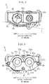
- FIGS. 2-5 respectively illustrate a plan view, a side view, a front view, and a rear view of the balancer 5.
- the balancer 5 is formed as a unit, and includes: driving and driven balancer shafts (i.e., a pair of balancer shafts) 15 and 25 extending in the fore and aft direction (which is parallel to the crankshaft) of the engine and disposed side by side in the lateral (i.e., the width) direction (which is orthogonal to the vertical direction and to the fore and aft direction of the engine); a balancer housing 7 which houses the balancer shafts 15 and 25; a housing cover 17 which covers the top of the balancer housing 7; and a thrust plate 27 which covers the rear end of the balancer housing 7.
- driving and driven balancer shafts i.e., a pair of balancer shafts
- 15 and 25 extending in the fore and aft direction (which is parallel to the crankshaft) of the engine and disposed side by side in the
- the fore and aft direction of the engine will be simply referred to as the "fore and aft direction”
- the front side in the fore and aft direction of the engine e.g., a second end in the fore and aft direction of the engine
- the rear end in the fore and aft direction of the engine e.g., a first side in the fore and aft direction of the engine
- the lateral direction of the engine will be simply referred to as the "lateral direction”
- the left in the lateral direction of the engine will be simply referred to as the "left”
- the right in the lateral direction of the engine will be simply referred to as the "right”
- the vertical direction of the engine will be simply referred to as the "vertical direction.”
- the balancer housing 7 has no split surfaces, and is an aluminum die cast housing which is casted as one piece. As illustrated in FIG. 6 , the balancer housing 7 includes: a front bearing wall 37 supporting an intermediate portion (i.e., the rear end of a shaft shaft extension 15f, which will be described later) in the axial direction of the driving balancer shaft 15 and the front end of a driven balancer shaft 25; a rear bearing wall 47 supporting the rear ends of the respective balancer shafts 15 and 25; a distal bearing wall 57 supporting the front end (i.e., the front end of the shaft extension 15f) of the driving balancer shaft 15; a housing body 67 located between the front bearing wall 37 and the rear bearing wall 47; a housing extension 77 located between the distal bearing wall 57 and the front bearing wall 37; and a gear housing 87 for housing engaging gears 75a and 85a which will be described later.
- a front bearing wall 37 supporting an intermediate portion (i.e., the rear end of a shaft shaft extension 15f, which will be
- a left bearing hole 37a extending in the fore and aft direction and rotatably supporting an intermediate portion (i.e., the rear end of the shaft extension 15f) in the axial direction of the driving balancer shaft 15 and a right bearing hole 37b extending in the fore and aft direction and rotatably supporting the front end of the driven balancer shaft 25 are disposed side by side in the lateral direction, and penetrate the front bearing wall 37.
- the inner diameter of the left bearing hole 37a for supporting the driving balancer shaft 15 is larger than the inner diameter of the right bearing hole 37b for supporting the driven balancer shaft 25.
- Needle rolling bearings 31 and 61 i.e., rolling bearings
- Approximately cylindrical mounting eyes 37c and 37d are respectively formed at both ends, in the lateral direction, of the front bearing wall 37, and project upward from the top of the front bearing wall 37.
- Mounting holes 37e and 37f which vertically penetrate end portions of the front bearing wall 37 and through which bolts (not shown) for fixing the balancer housing 7 to the bottom surface of the lower block 21 are inserted, are formed at the centers of the mounting eyes 37c and 37d.
- Approximately the lower half of a cylindrical pin 37g is inserted in the left mounting hole 37e. This pin 37g is used as a positioning pin to be inserted in a bolt insertion hole 21k formed in the bottom surface of the lower block 21, in attaching the balancer housing 7 to the lower block 21.
- the pin 37g is formed to allow a bolt to penetrate therethrough.
- a cap 45 is fitted onto the front edge of the right bearing hole 37b in order to isolate the hole 37b from oil stored outside the balancer housing 7 in principle.
- This cap 45 serves as part of a third lubricating-oil passageway 97, which will be described later.
- two bearing holes 47a and 47b extending in the fore and aft direction and rotatably supporting the rear ends of the balancer shafts 15 and 25 are disposed side by side in the lateral direction, and penetrate the rear bearing wall 47.
- the inner diameter of the left bearing hole 47a for supporting the driving balancer shaft 15 is equal to the inner diameter of the right bearing hole 47b for supporting the driven balancer shaft 25.
- needle rolling bearings 41 and 41 are inserted into the bearing holes 47a and 47b.
- Approximately cylindrical mounting eyes 47c and 47d are respectively formed at both ends, in the lateral direction, of the rear bearing wall 47, and project upward from the top of the rear bearing wall 47.
- Mounting holes 47e and 47f which vertically penetrate the rear bearing wall 47 and through which bolts for fixing the balancer housing 7 are inserted, are formed at the centers of these mounting eyes 47c and 47d.
- approximately the lower half of a positioning pin 47g is inserted in the right mounting hole 47f. This pin 47g is used as a positioning pin to be inserted in a bolt insertion hole 211 formed in the bottom surface of the lower block 21.
- the height of the rear bearing wall 47 is larger than that of the front bearing wall 37.
- the bottom end of the rear bearing wall 47 is located below the bottom end of the front bearing wall 37.
- a bearing hole 57a is formed through the distal bearing wall 57 to extend in the fore and aft direction and rotatably support the front end (i.e., the front end of the shaft extension 15f) of the driving balancer shaft 15.
- a needle rolling bearing 51 is inserted into the bearing hole 57a.
- Approximately cylindrical mounting eyes 57b and 57c are respectively formed at both ends, in the lateral direction, of the distal bearing wall 57, and project upward from the top of the distal bearing wall 57.
- Mounting holes 57d and 57e which vertically penetrate an end portion of the distal bearing wall 57 and through which bolts for fixing the balancer housing 7 are inserted, are formed at the centers of the mounting eyes 57b and 57c.
- the bearing hole 57a of the distal bearing wall 57 has the smallest inner diameter
- the bearing hole 47a of the rear bearing wall 47 has the largest inner diameter.
- the inner diameter of the bearing hole 37b of the front bearing wall 37 is smaller than the bearing hole 47b of the rear bearing wall 47.
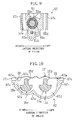
- the housing body 67 extends in the fore and aft direction to couple the front bearing wall 37 and the rear bearing wall 47. As illustrated in FIG. 10 , the housing body 67 includes: a bottom wall 67a; and side walls 67b and 67c extending from both ends, in the lateral direction, of this bottom wall 67a.
- the side walls 67b and 67c are open (i.e., have apertures 67o) at the tops thereof.
- the bottom wall 67a When viewed from the front side of the engine, the bottom wall 67a has two downward protuberances whose both ends in the lateral direction are smoothly coupled to the side walls 67b and 67c.
- two main-weight housings 67d and 67e disposed side by side in the lateral direction and housing main-weight parts 15d and 25c (i.e., balancer weight parts), which will be described later, of the respective balancer shafts 15 and 25, are formed in the housing body 67.
- the left main-weight housing 67d housing the main-weight part 15d of the driving balancer shaft 15 has a volume larger than that of the right main-weight housing 67e housing the main-weight part 25c of the driven balancer shaft 25.
- the bottom wall 67a has three drain oil openings 67f, 67g, and 67h for gravity drain of lubricating oil (or oil) accumulated in the main-weight housings 67d and 67e (see, FIG. 6 ).
- the bottom wall 67a projects below the bottom end of the front bearing wall 37, and has its bottom end (i.e., the vertex of the left protuberance) located approximately at the same level as the bottom end of the rear bearing wall 47.
- the top ends of the side walls 67b and 67c are located below the top ends of the front and rear bearing walls 37 and 47.
- Two bosses 67i and 67j; 67k and 671 for attaching the housing cover 17 project on each of the top surfaces of the side walls 67b and 67c are spaced apart from each other in the fore and aft direction (see, FIG. 6 ), and ridges 67m and 67n are formed on, and project upward from, the inner end portion, in the lateral direction, of the top surfaces of the side walls 67b and 67c, and extend in the fore and aft direction.
- the top ends of these ridges 67m and 67n are located below the top ends of the bosses 67i, 67j, 67k, and 671.
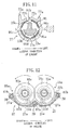
- the housing extension 77 extends in the fore and aft direction to couple the distal bearing wall 57 and the front bearing wall 37 to each other, and has an approximately cylindrical shape as illustrated in FIG. 11 .
- a sub-weight housing 77e for housing a sub-weight part 15e, which will be described later, of the shaft extension 15f of the driving balancer shaft 15.
- the front end of this housing extension 77 has a lubrication hole 77b for supplying lubricating oil vertically penetrating a portion of the housing extension 77 near the top thereof.
- the upper half of the outer surface of the housing extension 77 is provided with walls 77a surrounding the lubrication hole 77b to form L-shaped space in plan view and extending upward.
- the space which has an L-shape in plan view and is surrounded with the walls 77a forms an oil collection part 77c having an open top and collecting oil dropped from the engine body 1.
- the lubrication hole 77b forms an oil supply hole for supplying oil collected in the oil collection part 77c to needle rolling bearings 31 and 51 inserted into the bearing holes 37a and 57a of the front and distal bearing walls 37 and 57.
- This oil supply hole allows the inside of the oil collection part 77c to communicate with the inside of the housing extension 77.
- the lubrication hole 77b and the walls 77a form part of a first lubricating-oil passageway 93 which will be described later.
- An approximately cylindrical spacer 91 is inserted in the sub-weight housing 77e.
- This spacer 91 provides spacing, in the fore and aft direction, between the needle rolling bearings 51 and 31 provided in the bearing holes 57a and 37a of the distal and front bearing walls 57 and 37.
- the spacer 91 has: an annular trench 91a formed at a position associated with the lubrication hole 77b in the fore and aft direction and extending along the entire periphery of the outer surface of the spacer 91; and four supply through holes 91b, 91c, 91d, and 91e penetrating the spacer 91 laterally and vertically.
- the top and bottom supply through holes 91b and 91d vertically penetrating the spacer 91 are disposed in the vertical direction so as to overlap with part of the lubrication hole 77b in plan view.
- the annular trench 91a and the supply through holes 91b, 91c, 91d, and 91e also form part of the first lubricating-oil passageway 93.
- the gear housing 87 further extends rearward from the rear end surface of the rear bearing wall 47 to be provided at the rear end of the balancer housing 7. As illustrated in FIG. 12 , when viewed from the front side of the engine, the gear housing 87 has two downward protuberances so as to house approximately lower halves of the engaging gears 75a and 85a provided in the respective balancer shafts 15 and 25 and configured to implement synchronous rotation of the balancer shafts 15 and 25. Three bolt insertion holes 87a, 87b, and 87b for attaching the thrust plate 27 are respectively formed at the center and both ends in the rear end of the gear housing 87. As illustrated in FIG.
- the thrust plate 27 is attached to the rear end (i.e., the open end) 87c of the gear housing 87, thereby forming a gear housing room 87d which is open at the top and covers approximately lower halves of the engaging gears 75a and 85a.
- the balancer housing 7 as a whole has a substantially box shape which has the aperture 67o at the top and is open at the rear end.
- the left portion of the gear housing 87, the left bearing hole 47a of the rear bearing wall 47, the left main-weight housing 67d, the left bearing hole 37a of the front bearing wall 37, the sub-weight housing 77e, and the bearing hole 57a of the distal bearing wall 57 form a space for housing the driving balancer shaft 15.
- the right portion of the gear housing 87, the right bearing hole 47b of the rear bearing wall 47, the right main-weight housing 67e, and the right bearing hole 37b of the front bearing wall 37 form a space for housing the driven balancer shaft 25.
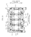
- the balancer housing 7 is located at the bottom of the engine body 1 by attaching the bearing walls 37, 47, and 57 to bearing walls 21e, 21f, and 21g (see, FIG. 13 ) provided in the lower block 21 (i.e., the engine body 1) and used for supporting the crankshaft 9. More specifically, the distal bearing wall 57 is attached to the bearing wall 21 e located in front of a first cylinder 21a, by tightening bolts inserted in the mounting holes 57d and 57e to bolt insertion holes 21h and 21i formed in the bottom surface of the lower block 21.
- the front bearing wall 37 is attached to the bearing wall 21f located between the first cylinder 21a and a second cylinder 21b, by tightening bolts inserted in the mounting holes 37e and 37f to bolt insertion holes 21k and 21j formed in the bottom surface of the lower block 21.
- the rear bearing wall 47 is attached to the bearing wall 21g located between a third cylinder 21c and a fourth cylinder 21 d, by tightening bolts inserted in the mounting holes 47e and 47f to bolt insertion holes 21m and 211 formed in the bottom surface of the lower block 21.
- the front and rear bearing walls 37 and 47 are attached to the bearing walls 21f and 21g located at the front and rear of two adjacent cylinders (i.e., the second and third cylinders 21b and 21c), and thereby, the aperture 67o of the balancer housing 7 extends across the second and third cylinders 21b and 21c, as illustrated in FIG. 14 .
- the driving and driven balancer shafts 15 and 25 are positioned to extend in the fore and aft direction in the balancer housing 7.
- the driving balancer shaft 15 is rotatably supported by the bearing holes 37a, 47a, and 57a respectively formed in the front bearing wall 37, the rear bearing wall 47, and the distal bearing wall 57
- the driven balancer shaft 25 is rotatably supported by the bearing holes 37b and 47b respectively formed in the front bearing wall 37 and the rear bearing wall 47.
- the front end of the driving balancer shaft 15 further extends forward beyond the front end of the driven balancer shaft 25.
- the driving balancer shaft 15 has the shaft extension 15f extending forward beyond the driven balancer shaft 25.
- the shaft axes of the balancer shafts 15 and 25 are arranged in parallel with each other so as to be symmetric in the same plane with respect to the vertical plane passing through the shaft axis of the crankshaft 9.
- the driving balancer shaft 15 includes: a distal journal 15a; a front journal 15b; a rear journal 15c; a main-weight part 15d; a sub-weight part 15e; and an engaging gear 75a.
- a driven sprocket (i.e., a driving-power transmission part) 35 is attached to a portion (i.e., the tip) of the driving balancer shaft 15 located in front of the distal journal 15a.
- the driving balancer shaft 15 is configured to be driven by receiving driving power from the crankshaft 9 through the driven sprocket 35.
- the distal, front, and rear journals 15a, 15b, and 15c are respectively supported by the bearing holes 57a, 37a, and 47a formed in the distal, front, and rear bearing walls 57, 37, and 47 with the needle rolling bearings 51, 31, and 41 provided on the outer peripheries of the distal, front and rear journals 15a, 15b, and 15c.
- supporting the driving balancer shaft 15 by a portion (i.e., the distal journal 15a) of the driven sprocket 35 can reduce bending of the axis of the shaft extension 15f, thereby reducing vibration of the driven sprocket 35.
- the distal journal 15a has the smallest outer diameter
- the rear journal 15c has the largest outer diameter.
- the needle rolling bearings 31, 41, and 51 include: annular outer races 31a, 41a, and 51a fitted internally, and fixed, to the inner surfaces of the bearing holes 37a, 47a, and 57a so as to be unrotatable; annular inner races 31b, 41b, and 51b fitted internally, and fixed, to the outer surfaces of the journals 15b, 15c, and 15a so as to be unrotatable; a plurality of needle rollers 31c, 41c, and 51c provided between the outer races 31a, 41a, and 51a and the inner races 31b, 41b, and 51b, respectively; and annular holders 31d, 41d, and 51d holding these needle rollers 31c, 41c, and 51c so as to allow rolling motion of the needle rollers 31c, 41c, and 51c in the peripheral direction.
- the holders 31d, 41d, and 51d are configured to rotate in the bearing holes 37a, 47a, and 57a according to the rolling motion of the needle rollers 31c, 41c, and 51c.
- the outer race 51a of the needle rolling bearing 51 placed on the distal journal 15a has a U shape in cross section, and the needle roller 51c and the holder 51d are incorporated therein beforehand.
- the outer races 31a and 41a of the needle rolling bearings 31 and 41 placed on the front and rear journals 15b and 15c have simple cylindrical shapes, and a pre-assembly unit of the associated needle rollers 31c and 41c and holders 31d and 41d are separated from the outer races 31a and 41a, as illustrated in FIG. 15 .
- the outer race 41a of the needle rolling bearing 41 placed on the rear journal 15c extends rearward beyond the inner race 41b and the holder 41d, and surrounds the entire periphery of the front end of the engaging gear 75a.
- the main-weight part 15d is located between the front journal 15b and the rear journal 15c, and is housed in the left main weight housing 67d of the housing body 67. As illustrated in FIG. 10 , this main-weight part 15d has an approximately semicircular shape in order to provide weight imbalance by forming a recess in an approximately semicircular region of the outer surface of the driving balancer shaft 15 such that the recess becomes symmetric with respect to the vertical plane passing through the shaft axis of the driving balancer shaft 15 when viewed from the front side of the engine. In other words, the main-weight part 15d has an approximately semicylincrical mass portion 15g whose barycenter is eccentric from the shaft center.
- the mass portion 15g is formed in a portion 15i near the front journal 15b of the main-weight part 15d. Accordingly, the barycenter G2 of the main-weight part 15d is located at a position closer to the rear, than that of an eccentric portion formed between the front journal 15b and the rear journal 15c (see, FIG. 15 ).
- the main-weight part 15d is formed to have an outer diameter of its rotational path larger than the outer diameter of the front and rear journals 15b and 15c. More specifically, the outer diameter of rotational path of the main-weight part 15d is larger than the outer diameter of the inner race 31b of the needle rolling bearing 31 fitted into the front journal 15b, but is smaller than the inner diameter of the outer race 41 a of the needle rolling bearing 41 fitted into the rear journal 15c.
- the sub-weight part 15e is located between the distal journal 15a and the front journal 15b, and is housed in the sub-weight housing 77e of the housing body 67.
- This sub-weight part 15e has an approximately semicircular shape in order to provide weight imbalance by forming a recess in an approximately semicircular region of the outer surface of the driving balancer shaft 15 such that the recess becomes symmetric with respect to the vertical plane passing through the shaft axis of the driving balancer shaft 15 when viewed from the front side of the engine.
- the sub-weight part 15e has an approximately semicylincrical mass portion 15h whose barycenter is eccentric from the shaft center.
- the outer diameter of rotational path of this sub-weight part 15e is smaller than the outer diameter of the main-weight part 15d, and is approximately equal to the outer diameters of the distal and front journals 15a and 15b.
- the engaging gear 75a is adjacent to the rear of the needle rolling bearing 41 (i.e., the rolling bearing) of the driving balancer shaft 15 at the rear end of the main-weight part 15d, and includes: a gear body 75c fitted with the driving balancer shaft 15; a front cylinder 75b (i.e., a movement restriction part) extending forward from the front end surface of the gear body 75c to the inside of the outer race 41a of the needle rolling bearing 41; and a rear cylinder 75g extending rearward from the rear end surface of the gear body 75c.
- the gear body 75c is made of a helical gear which is engaged with a gear body 85c (i.e., a helical gear), which will be described later, of the driven balancer shaft 25.
- An annular step 75h surrounding the rear cylinder 75g when viewed from the rear side of the engine is formed in the rear side surface of the gear body 75c.
- annular projection 75d projecting radially outwardly is formed on the front end of the outer surface of the front cylinder 75b, whereas an annular flange 75e extending radially outwardly is formed on the rear end of the outer surface of the rear cylinder 75g.
- the annular projection 75d provides space in the fore and aft direction between the annular projection 75d and a ring plate 100a located at the front end edge of the rear journal 15c, and restricts the movement in the fore and aft direction of the holder 41d of the needle rolling bearing 41 placed on the rear journal 15c.
- the tip in the radial direction (i.e., the outer surface) of this annular projection 75d is located closer to the inner surface of the outer race 41a of the needle rolling bearing 41, thereby restricting an excess supply of oil scattered with the rotation of the engaging gear 75a to the needle rolling bearing 41.
- the position of the outer surface of the annular flange 75e approximately matches the position of the outer surface of the step 75h when viewed from the rear of the engine.
- the annular flange 75e forms an annular thrust control trench 75f together with the step 75h and the rear cylinder 75g.
- a thrust control portion 27a, which will be described later, of the thrust plate 27 is fitted into this thrust control trench 75f.
- the thrust control trench 75f is slidable along the thrust control portion 27a.
- Movement in the fore and aft direction of a holder 31d of the needle rolling bearing 31 supporting the front journal 15b is controlled with the ring plates 100a and 100b disposed at, and fixed to, both sides, in the fore and aft direction, of the inner race 31b fitted internally, and fixed, to the front journal 15b.
- the driven balancer shaft 25 includes: a front journal 25a; a rear journal 25b; a main-weight part 25c; and an engaging gear 85a.
- the front and rear journals 25a and 25b are respectively supported by the bearing holes 37b and 47b formed in the front and rear bearing walls 37 and 47 with the needle rolling bearings 61 and 41 placed on the outer surfaces thereof. Between the journals 25a and 25b, the outer diameter of the rear journal 25b is larger than the outer diameter of the front journal 25a.
- the needle rolling bearings 61 and 41 respectively include: annular outer races 61 a and 41 a; annular inner races 61b and 41b; a plurality of needle rollers 61c and 41c; and annular holders 61d and 41d.
- the outer race 61a and the holder 61d are integrated.
- the outer race 41a extends rearward beyond the inner race 41b and the holder 41d, and surrounds the entire periphery of the front end of the engaging gear 85a.
- the main-weight part 25c is formed between the front journal 25a and the rear journal 25b, and is housed in the right main weight housing 67e of the housing body 67.
- this main-weight part 25c has an approximately semicircular shape in order to provide barycenter imbalance by forming a recess in an approximately semicircular region of the outer surface of the driven balancer shaft 25.
- the main-weight part 25c has an approximately semicylincrical mass portion 25e whose barycenter is eccentric from the shaft axis of the balancer shaft.
- the outer diameter of rotational path of the main-weight part 25c is larger than those of the front and rear journals 25a and 25b. More specifically, the outer diameter of rotational path of the main-weight part 25c is larger than the outer diameter of the inner race 61b of the needle rolling bearing 61 fitted into the front journal 25a, and is smaller than the inner diameter of the outer race 41a of the needle rolling bearing 41 fitted into the rear journal 25b.
- the reinforcing rib 15j, 25f is formed integrally with the mass portion 15g, 25e between the front journal 15b, 25a and the rear journal 15c, 25b of the driving or driven balancer shaft 15, 25.
- a reinforcing rib 15k is formed integrally with the mass portion 15h between the distal journal 15a and the front journal 15b of the driving balancer shaft 15. In this manner, the journals are reinforced against axis bending.
- the engaging gear 85a is provided adjacent to the rear of the needle rolling bearing 41 of the driven balancer shaft 25 at the rear end of the driven balancer shaft 25 at the rear of the main-weight part 25c.
- the engaging gear 85a includes: a gear body 85c; a front cylinder 85b (i.e., a movement restriction part); and a rear cylinder 85g.
- the gear body 85c is made of a helical gear which has the same diameter as the gear body 75c of the driving balancer shaft 15 and is engaged with the gear body 75c. In this manner, both of the gear bodies 75c and 85c of the driving and driven balancer shafts 15 and 25 are made of helical gears, thereby reducing noise during the rotation of these balancer shafts 15 and 25.
- an annular step 85h is formed in the rear side surface of the gear body 85c to surround the rear cylinder 85g when viewed from the rear side of the engine.
- annular projection 85d projecting radially outwardly is formed in the front end of the outer surface of the front cylinder 85b, whereas an annular flange 85e extending radially outwardly is formed in the rear end of the outer surface of the rear cylinder 85g.
- These annular projection 85d and annular flange 85e have substantially the same functions as the annular projection 75d and the annular flange 75e of the driving balancer shaft 15.
- the location and structure of the needle rolling bearing 41 at the rear end of the driven balancer shaft 25 are substantially the same as those of the needle rolling bearing 41 of the driving balancer shaft 15 including the ring plate 100a, and thus description thereof is omitted.
- the synchronous rotation of the driving balancer shaft 15 and the driven balancer shaft 25 causes the mass portion 15g of the main-weight part 15d of the driving balancer shaft 15 and the mass portion 25e of the main-weight part 25c of the driven balancer shaft 25 to synchronously rotate in opposite directions, while being always at the same height. Since the balancer shafts 15 and 25 rotate at high speed in the directions indicated by the arrows in FIG. 12 , oil which has entered the left and right main-weight housings 67d and 67e is swept diagonally upward by the mass portions 15g and 25e.
- the driven sprocket 35 of the driving balancer shaft 15 is a small-diameter gear in which the number of teeth is half of that in the driving sprocket 19 of the crankshaft 9, thereby allowing the driving and driven balancer shafts 15 and 25 to rotate with a number of rotations twice as large as that of the engine.
- the driving balancer shaft 15 includes the shaft extension 15f extending forward beyond the driven balancer shaft 25, and is driven by receiving driving power from the crankshaft 9 through the driven sprocket 35 at the tip of the shaft extension 15f.
- an eccentric load in the axial direction causes imbalance in rotation of the shaft extension 15f, thereby causing additional axis bending of the shaft extension 15f of the driving balancer shaft 15.
- the front journal 15b and the needle rolling bearing 31 serving as bearings in an intermediate portion of the driving balancer shaft 15 are not in surface contact, which is employed between conventional metal bearings, but are in line contact with each other. Accordingly, uneven distribution of loads can occur in rotation with tilt caused by axis bending, and thus a new problem can arise in the bearing configuration.
- the shaft extension 15f has the sub-weight part 15e, and thus imbalance in load in the axial direction can be reduced, thereby reducing axis bending of the driving balancer shaft 15.
- the barycenter of the weight part of the driving balancer shaft 15 shifts forward from the barycenter of the weight part (i.e., only the main-weight part) of a conventional balancer, thereby causing a shift between the barycenter of the weight parts 15d and 15e of the driving balancer shaft 15 and the barycenter G1 of the main-weight part 25c of the driven balancer shaft 25. In this state, it is difficult to reduce vibration due to rotational imbalance of the crankshaft 9.
- the balancer 5 has a configuration in which the position of the barycenter G2 of the main-weight part 15d of the driving balancer shaft 15 is adjusted such that the barycenter of the weight parts 15d and 15e of the driving balancer shaft 15 matches the barycenter G1 of the main-weight part 25c of the driven balancer shaft 25.
- the main-weight part 15d of the driving balancer shaft 15 has no eccentric portions in the portion 15i near the front journal 15b between the front journal 15b and the rear journal 15c. Accordingly, the barycenter G2 of the main-weight part 15d of the driving balancer shaft 15 is located closer to the rear, than the barycenter G1 of the main-weight part 25c of the driven balancer shaft 25 having the eccentric portion between the front journal 25a and the rear journal 25b.
- the barycenter G2 of the main-weight part 15d of the driving balancer shaft 15 is located closer to the rear than the barycenter G1 of the main-weight part 25c of the driven balancer shaft 25.
- This configuration can reduce forward movement of the barycenter of the weight parts 15d and 15e, and the barycenter of the weight parts 15d and 15e of the driving balancer shaft 15 matches the barycenter G1 of the main-weight part 25c of the driven balancer shaft 25.
- the housing cover (i.e., a cover member) 17 is made of a pressed steel plate, and as illustrated in FIG. 3 , is tightened to the bosses 67i, 67j, 67k, and 671 projecting from the top of the side walls 67b and 67c of the housing body 67 with the bolts (e.g., 49, 49) so as to cover the aperture 67o of the housing body 67.
- the housing cover 17 is located below the tops of the mounting eyes 37c, 37d, 47c, and 47d.
- the housing cover 17 provided in this manner can reduce unwanted flow of oil supplied to the bearing (not shown) of the crankshaft 9 or used for piston cooling, into the main-weight housings 67d and 67e even in the configuration in which the housing body 67 forming the main-weight housings 67d and 67e has an aperture 67o at the top thereof and the aperture 67o is formed across the second and third cylinders 21b and 21 c.
- the housing cover 17 is in the shape of a plate thinner than a member forming the housing body 67, and has its stiffness increased by forming a plurality of projecting ribs (e.g., 17a, 17b) extending in the fore and aft direction and in the lateral direction. As illustrated in FIG. 10 , the housing cover 17 extends along the outer periphery of rotational path of the main-weight parts 15d and 25c in cross section. In other words, the housing cover 17 has two upward protuberances when viewed from the front side of the engine. In this manner, the housing cover 17 can be located closer to the main-weight parts 15d and 25c. This positioning, together with the small thickness of the housing cover 17, can reduce the height of the balancer housing 7. Accordingly, the axes of the balancer shafts 15 and 25 can be located closer to the engine.
- the housing cover 17 extends laterally outwardly beyond both sides, in the lateral direction, of the housing body 67. More specifically, the housing cover 17 extends to a portion near the outer side edges of the side walls 67b and 67c beyond the ridges 67m and 67n formed on the inner side edges of the side walls 67b and 67c of the housing body 67, and the housing cover 17 has downward bending portions 17c, 17c at both ends thereof.
- the presence of the bosses (e.g., 67i, 67j, 67k) described above provides gaps 29 and 29 between the housing cover 17 and the ridges 67m and 67n, thereby allowing the inside of the housing body 67 to communicate with the outside through these gaps 29 and 29.
- the housing cover 17 additionally has upward bending portions 17d and 17e at both sides thereof in the fore and aft direction.
- the front surface of the front bending portion 17d is close to the rear end surface of the front bearing wall 37, and the rear surface of the rear bending portion 17e is close to the front end surface of the rear bearing wall 47.
- This configuration can prevent oil which has accumulated on the upper surface of the housing cover 17 from entering the main-weight housings 67d and 67e.
- the thrust plate 27 is provided at the rear end of the gear housing 87 forming the open end 87c at the rear of the balancer housing 7, and covers a portion of the open end 87c under the line connecting the centers of the balancer shafts 15 and 25 (see, FIG. 5 ).
- This thrust plate 27 is a pressed product made of a metal material exhibiting high abrasion resistance, and has a rounded inverted trapezoidal shape. Two approximately semicircular notches which are open at their tops are formed in a linear top 27b of the thrust plate 27.
- the thrust plate 27 has three through holes 27c, 27c, and 27c at positions corresponding to the three bolt insertion holes 87a, 87b, and 87b of the gear housing 87.
- the thrust plate 27 is attached to the balancer housing 7 by screwing bolts 39, 39, and 39 inserted in the through holes 27c, 27c, and 27c into the bolt insertion holes 87a, 87b, and 87b of the gear housing 87, with the peripheries (hereinafter referred to as a pair of thrust control portions) 27a and 27a of a pair of notches formed in the thrust plate 27 fitted into the thrust control trenches 75f and 85f of the engaging gears 75a and 85a.
- the step 75h and 85h of the gear bodies 75c and 85c come into contact with the front surfaces of the thrust control portions 27a and 27a, and the front end surfaces of the annular flanges 75e and 85e come into contact with the rear surfaces of the thrust control portions 27a and 27a, thereby controlling a thrust shift caused by a thrust applied from both of the front and rear ends of the balancer shafts 15 and 25.
- the thrust plate 27 further includes: two supply oil trenches 27d and 27d which are open at the front surface of the thrust plate 27; and two supply oil trenches 27e and 27e which are open at the rear surface of the thrust plate 27.
- These supply oil trenches extend from the peripheries 27a and 27a of the notches to the positions corresponding to the bottoms of the gear bodies 75c and 85c. Oil accumulated in the gear housing 87 is smoothly supplied to space between the rear end surfaces of the gear bodies 75c and 85c and the front surface of the thrust plate 27 with the rotation of the engaging gears 75a and 85a.
- the front supply oil trench 27d and the rear supply oil trench 27e are symmetrical at the front and back sides of the thrust plate 27, i.e., oil supply paths can also be formed even when the thrust plate 27 is attached to the gear housing 87 with the front and back sides of the thrust plate 27 reversed.
- Each of the balancer shafts 15 and 25 is inserted through the open end 87c at the rear of the balancer housing 7, and is placed in the balancer housing 7.
- the driving balancer shaft 15 is inserted such that the shaft extension 15f of the driving balancer shaft 15 passes through a left portion of the gear housing 87, the left bearing hole 47a of the rear bearing wall 47, the left main-weight housing 67d, the left bearing hole 37a of the front bearing wall 37, the sub-weight housing 77e, and the bearing hole 57a of the distal bearing wall 57 in this order.
- the driven balancer shaft 25 is inserted such that the front journal 25a of the driven balancer shaft 25 passes through a right portion of the gear housing 87, the right bearing hole 47b of the rear bearing wall 47, the right main-weight housing 67e, and the right bearing hole 37b of the front bearing wall 37 in this order.
- the inner race 51b of the needle rolling bearing 51 and a stopper ring 100c associated with the inner race 51b are press fitted with the distal journal 15a of the driving balancer shaft 15.
- the ring plates 100a and 100b and the inner races 31 band 41b of the needle rolling bearings 31 and 41 are press fitted with the front and rear journals 15b and 15c of the driving balancer shaft 15, and the holders 31d and 41d and the needle rollers 31c and 41c are attached to the front and rear journals 15b and 15c.
- the engaging gear 75a is press fitted with the rear end of the shaft.
- the inner race 61b of the needle rolling bearing 61 and a stopper ring 100d associated with the inner race 61b are press fitted with the front journal 25a of the driven balancer shaft 25.
- the ring plate 100a and the inner race 41b of the needle rolling bearing 41 are press fitted with the rear journal 25b of the driven balancer shaft 25.
- the holder 41d and the needle roller 41c are attached to the rear journal 25b.
- the engaging gear 85a is press fitted with the rear end of the shaft.
- the pre-assembly unit illustrated in FIG. 15 is prepared.
- the outer race 51a is press fitted with the bearing hole 57a of the distal bearing wall 57 with the needle roller 51c and the holder 51d placed in the bearing hole 57a, and the spacer 91 is attached to this bearing hole 57a.
- the outer races 31a and 41a are press fitted with the left bearing holes 37a and 47a of the front and rear bearing walls 37 and 47.
- stopper pins 101 for controlling the position of, and preventing slipping-out of, the outer races 31a and 41a are press fixed to the balancer housing 7 from outside the balancer housing 7 along the radial direction of the balancer housing 7 in such a manner that the thickness of the stopper pins 101 does not exceed the thicknesses of the outer races 31a and 41a.
- stopper plates 102 for preventing slipping-out of both of the outer races 41a and 41a at the rear are bolted to the balancer housing 7 in such a manner that the thickness of the stopper plates 102 does not exceed the thicknesses of the outer races 31a and 41a.
- the outer race 61a is press fitted with the right bearing hole 37b of the front bearing wall 37 with the needle roller 61c and the holder 61d placed in the right bearing hole 37b, and the outer race 41a is press fitted with the right bearing hole 47b of the rear bearing wall 47.
- stopper pins 101 for controlling the position of, and preventing slipping-out of, the outer races 61a and 41a are press fixed to the balancer housing 7 from outside the balancer housing 7 along the radial direction of the balancer housing 7 in such a manner that the thickness of the stopper pins 101 does not exceed the thicknesses of the outer races 61 a and 41a.
- the driving and driven balancer shafts 15 and 25 are inserted into the balancer housing 7 with the engaging gears 75a and 85a engaged with each other.
- the outer diameter of rotational path of the main-weight part 15d of the driving balancer shaft 15 is smaller than the inner diameter of the outer race 41a fitted into the rear journal 15c.
- the outer diameter of rotational path of the sub-weight part 15e is smaller than the outer diameter of rotational path of the main-weight part 15d, and is approximately equal to the outer diameter of the distal and front journals 15a and 15b. This configuration can achieve smooth insertion of the driving balancer shaft 15.
- the outer diameter of rotational path of the main-weight part 25c of the driven balancer shaft 25 is smaller than the inner diameter of the outer race 41 a fitted into the rear journal 25b, smooth insertion of the driven balancer shaft 25 can be achieved.
- the driving and driven balancer shafts 15 and 25 are placed in the balancer housing 7, and then the thrust plate 27 is attached to the thrust control trenches 75f and 85f of the engaging gears 75a and 85a with the thrust control portions 27a and 27a inserted in the thrust control trenches 75f and 85f from below, thereby covering the open end 87c of the balancer housing 7.
- the journals 15a, 15b, and 15c; 25a and 25b are respectively supported by the bearing holes 57a, 37a, and 47a; 37b and 47b with the needle rolling bearings 51, 31, and 41; 61 and 41 interposed therebetween. Accordingly, it is necessary to avoid a situation where the needle rolling bearings 51, 31, 41, 61, and 41 are immersed in oil. However, a necessary amount of oil needs to be supplied to the needle rolling bearings 51, 31, 41, 61, and 41.
- the balancer housing 7 includes: a first lubricating-oil passageway 93 for supplying oil to the distal and front journals 15a and 15b of the driving balancer shaft 15; a second lubricating oil passageway 95 for supplying oil to the rear journal 15c of the driving balancer shaft 15; a third lubricating-oil passageway 97 for supplying oil to the front journal 25a of the driven balancer shaft 25; and a fourth lubricating oil passageway 99 for supplying oil to the rear journal 25b of the driven balancer shaft 25.
- These lubricating oil passageways 93, 95, 97, and 99 are not used for force-feed lubrication to the journals 15a, 15b, 15c, 25a, and 25b, but are used for introducing part of oil which was supplied to the journals of the crankshaft 9 and dropped.
- the first lubricating-oil passageway 93 includes: a path (indicated by the arrow 93 a) passing through the lubrication hole 77b of the housing extension 77; a path (indicated by the arrow 93b) passing through, or around the periphery of, the spacer 91 to reach the bottom of the spacer 91; a path (indicated by the arrow 93c) passing through a gap between the sub-weight part 15e and the spacer 91 to reach the needle rolling bearing 31 (i.e., the front journal 15b); a path (indicated by the arrow 93d) for gravity drain of oil which has flown from the needle rolling bearing 31, to outside the balancer housing 7 through the drain oil opening 67f; and a path (indicated by the arrow 93e) for gravity drain of oil which has flown from the needle rolling bearing 51, to outside the balancer housing 7.
- Part of oil which has dropped from a portion near the bearing wall 21e in front of the first cylinder 21a in the engine body 1 accumulates in the oil collection part 77c having an L shape in plan view and surrounded with the walls 77a of the housing extension 77, and enters the balancer housing 7 through the lubrication hole 77b.
- This part of oil passes through the supply through hole 91b of the spacer 91, flows down between the spacer 91 and the sub-weight part 15e, and flows in the fore and aft direction between the sub-weight potion 15e and the spacer 91.
- oil which has passed through the lubrication hole 77b also flows downward along the annular trench 91a formed in the outer surface of the spacer 91, into a gap between the spacer 91 and the sub-weight part 15e through, for example, the lower supply through hole 91d located below the upper supply through hole 91b of the spacer 91.
- Oil which has flown rearward is supplied to the needle rolling bearing 31, and then is drained by gravity to outside the balancer housing 7 through the drain oil opening 67f.
- oil which has flown forward is supplied to the needle rolling bearing 51, and then is drained by gravity directly to outside the balancer housing 7 through the needle rolling bearing 51.
- the second lubricating oil passageway 95 includes, as main components: a path (indicated by the arrow 95a) extending from above the gear body 75c of the engaging gear 75a directly to the gear housing 87; a path (indicated by the arrow 95b) passing through a gap between the front end surface of the gear body 75c of the engaging gear 75a and the rear end surface of the top of the rear bearing wall 47; a path (indicated by the arrow 95c) passing through a gap between the front end surface of the gear body 75c of the engaging gear 75a and the rear end surface of the bottom of the rear bearing wall 47; and a path (indicated by the arrow 95d) for gravity drain of oil to outside the balancer housing 7 through the drain oil opening 67g.
- part of oil which has dropped from a portion near the bearing wall 21g between the third cylinder 21c and the fourth cylinder 21d in the engine body 1 enters the gear housing 87 from above the gear body 75c and through a gap between the front end surface of the gear body 75c and the rear end surface of the top of the rear bearing wall 47.
- This part of oil reaches the needle rolling bearing 41 (i.e., the rear journal 15c), while being agitated by the rotation of the engaging gear 75a in the gear housing 87.
- the annular projection 75d of the engaging gear 75a controls an excess supply of oil to the needle rolling bearing 41 as described above.
- the third lubricating-oil passageway 97 includes: a path (indicated by the arrow 97a) passing through an opening of the cap 45 provided at the right front end surface of the front bearing wall 37; a path (indicated by the arrow 97b) passing through a gap between the distal surface of the driven balancer shaft 25 and the cap 45 to reach the needle rolling bearing 61 (i.e., the front journal 25a); a path (indicated by the arrow 97c) passing through a gap between the main-weight part 25c and the bottom wall 67a of the housing body 67 from the needle rolling bearing 61; and a path (indicated by the arrow 97d) for gravity drain of oil to outside the balancer housing 7 through the drain oil opening 67h.
- the cap 45 includes: an annular portion 45a fitted with the right bearing hole 37b of the front bearing wall 37; and a disk part 45b covering the front end of the annular part 45a and having a flange projecting radially outwardly.
- the disk part 45b is open in an approximately upper half of a portion thereof associated with the inner space of the annular part 45a, and a recessed cut-out portion 45c with a shape obtained by cutting out a flange from an approximately left half of a portion thereof associated with the annular part 45a.
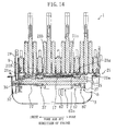
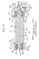
- the recessed cut-out portion 45c is flush with the front surface of the front bearing wall 37 of the balancer housing 7, as illustrated in FIGS. 17 and 19 .
- This recessed cut-out portion 45c forms an oil guide part which is formed in an upper portion of the cap 45 to allow the inside of the balancer housing 7 to communicate with the outside and is used for guiding oil which has dropped from the engine body 1 to the inside of the balancer housing 7.
- part of oil which has dropped from a portion near the bearing wall 21f between the first cylinder 21a and the second cylinder 21b in the engine body 1 flows down along the front surface of the front bearing wall 37, enters the balancer housing 7 through the recessed cut-out portion 45c of the disk part 45b, and is supplied to the needle rolling bearing 61 through a gap between the distal surface of the driven balancer shaft 25 and the rear side surface of the disk part 45b.
- Oil supplied to the needle rolling bearing 61 flows rearward in the right main-weight housing 67e, and is drained by gravity to outside the balancer housing 7 through the drain oil opening 67h.
- the fourth lubricating oil passageway 99 includes, as main components: a path (indicated by the arrow 99a) extending from above the gear body 85c of the engaging gear 85a directly to the gear housing 87; a path (indicated by the arrow 99b) passing through a gap between the front end surface of the gear body 85c of the engaging gear 85a and the rear end surface of the top of the rear bearing wall 47; a path (indicated by the arrow 99c) passing through a gap between the front end surface of the gear body 85c of the engaging gear 85a and the rear end surface of the bottom of the rear bearing wall 47; and a path (indicated by the arrow 99d) for gravity drain of oil to outside the balancer housing 7 through the drain oil opening 67h. Oil is supplied and drained through this fourth lubricating oil passageway 99 in the same manner as in the second lubricating oil passageway 95.
- the aperture 67o of the housing body 67 extends across the two adjacent cylinders 21b and 21c, and thus the main-weight parts 15d and 25c are long in the fore and aft direction.
- vibration due to rotational imbalance in the crankshaft 9 can be canceled without the necessity for increasing the lengths of the main-weight parts 15d and 25c in the radial direction, thereby reducing the size of the balancer housing 7.
- the outer diameter of rotational path of the main-weight parts 15d and 25c is smaller than the inner diameter of the outer races 41a and 41a of the needle rolling bearings 41 and 41 of the rear bearing wall 47, but is larger than the outer diameter of the inner races 31b and 61b of the needle rolling bearings 31 and 61 of the front bearing wall 37.
- the outer diameter of rotational path of the main-weight parts 15d and 25c is slightly smaller than the inner diameter of the outer races 41a and 41a fitted into the rear journals 15c and 25b.
- the outer diameter of the needle rolling bearings 41 and 41 which tends to be larger than the outer diameter of the metal bearings because of the structure, is reduced to a value slightly larger than the outer diameter of rotational path of the main-weight parts 15d and 25c, thereby achieving compact size of the needle rolling bearings 41 and 41.
- the balancer shafts 15 and 25 are inserted through the open end 87c of the balancer housing 7, thereby eliminating the necessity for vertically splitting the balancer housing 7, unlike conventional balancers. Accordingly, the distance in the lateral direction between the balancer shafts 15 and 25 can be reduced. As a result, the engaging gears 75a and 85a provided in the balancer shafts 15 and 25 can be made small, thereby achieving compact size of the balancer housing 7 for housing these gears.
- the engaging gears 75a and 85a are located at positions closer to the rear than the rear bearing wall 47, i.e., portions having the maximum outer diameter in the balancer shafts 15 and 25 are located at the end opposite the end through which the balancer shafts 15 and 25 are inserted. Accordingly, it is unnecessary to considerably increase the size of the bearing holes 37a, 37b, 47a, and 47b of the front and rear bearing walls 37 and 47 in order to insert the balancer shafts 15 and 25, thereby achieving compact size of the balancer housing 7.
- the thrust control portions 27a and 27a of the thrust plate 27 are inserted in the thrust control trenches 75f and 85f of the engaging gears 75a and 85a provided at the ends of the balancer shafts 15 and 25, thereby controlling a thrust shift caused by a thrust applied from both of the front and rear ends of the balancer shafts 15 and 25. Consequently, as compared to a configuration in which the thrust plate 27 is formed in, for example, the housing body 67, the structure can be simplified, and as a result, the balancer housing 7 can be made compact.
- the aperture 67o of the housing body 67 is covered with the plate-shaped housing cover 17 thinner than a member forming this housing body 67. Accordingly, the height of the housing body 67 can be reduced, and the shaft axes of the balancer shafts can be located at a higher level, as compared to the balancer housing having a thick upper wall.
- the foregoing configuration allows the balancer 5 of this example embodiment to be made compact in the vertical direction. Even when oil is poured in the oil pan 3 to the full level, the balancer 5 is only partially immersed in the oil (see, the oil level surface L in FIG. 4 ).
- the height of the balancer housing 7 is reduced so that the shaft axes of the balancer shafts are located at a higher level, thereby allowing the needle rolling bearings (e.g., 31, 41, 41) to be less likely to be immersed in oil.
- an excess supply of oil to the needle rolling bearings (e.g., 31, 41, 41) can be reduced, thereby ensuring smooth rotation of the needle rolling bearings (e.g., 31, 41, 41). Consequently, friction between the balancer shafts 15 and 25 and the bearing holes (e.g., 37a, 37b, 47a) can be reduced, thereby reducing fuel consumption.
- the pair of balancer shafts 15 and 25 is supported by the bearing holes 37a, 37b, 47a, and 47b with the needle rolling bearings 31, 41, and 61 interposed therebetween. Accordingly, as compared to the case of employing metal bearings, friction between the balancer shafts 15 and 25 and the bearings can be reduced, thereby reducing fuel consumption.
- the aperture 67o of the housing body 67 is covered with the housing cover 17, thereby reducing an unintentional supply of oil which has dropped from, for example, the crankshaft 9 to the needle rolling bearings 31, 41, and 61.
- the outer diameter of rotational path of the main-weight parts 15d and 25c is smaller than the inner diameter of the outer races 41a and 41a of the needle rolling bearings 41 and 41 of the rear bearing wall 47, and is larger than the outer diameter of the inner races 31b and 61b of the needle rolling bearings 31 and 61 of the front bearing wall 37. Accordingly, the balancer shafts 15 and 25 can be easily inserted through the end 87c at the rear of the balancer housing 7.
- the housing cover 17 extends along the outer periphery of rotational path of the main-weight parts 15d and 25c in cross section. Accordingly, it is possible to locate the housing cover 17 to partially enter the housing so that the shaft axes of the balancer shafts on the balancer housing 7 can be located at a higher level.
- the gaps 29 and 29 are provided between the housing cover 17 and the housing body 67 in the vertical direction, thereby causing oil swept by the mass portions 15g and 25e to pass through these gaps 29 and 29.
- the housing cover 17 extends laterally outwardly beyond both sides in the lateral direction of the aperture 67o. Thus, oil which has passed through the gaps 29 and 29 can be guided by the housing cover 17 and easily drained to outside the housing body 67.
- the housing cover 17 is located below the tops of the mounting eyes (e.g., 37c and 37d) in the vertical direction. Accordingly, even when the mounting eyes (e.g., 37c and 37d) have a small projection length, a sufficient distance in the vertical direction can be easily ensured between the housing cover 17 and the connecting rod.
- the above example embodiment employs the aluminum die cast balancer housing 7 which is casted as one piece.
- a balancer housing having split surfaces which are split in the fore and aft direction may be employed, for example.
- the cylindrical inner races 31b, 41b, 51b, and 61b and the ring plates 100a and 100b are used for the needle rolling bearings 31, 41, 51, and 61.
- these ring plates may be omitted, and inner races having U shapes in cross section may be used instead. If the materials for the balancer shafts 15 and 25 are compatible with the needle rollers 31c, 41c, 51c, and 61c, the inner races 31b, 41b, 51b, and 61b may be omitted.
- the above passageways may be replaced with lubricating oil passageways for force-feed lubrication to the journals 15a, 15b, 15c, 25a, and 25b.
- the weight parts 15d, 15e, and 25c have semicircular shapes when viewed from the front side of the engine, but may be in any shape as long as vibration due to rotational imbalance of the crankshaft 9 is canceled.
- the driving and driven balancer shafts 15 and 25 are inserted through the open end 87c at the rear of the balancer housing 7, but may be inserted through an open end located at the front side of the balancer housing 7.
- the example embodiment employs the engaging gears 75a and 85a including the gear bodies 75c and 85c made of helical gears.
- an engaging gear including a gear body made of a worm gear may be employed, for example.
- the thrust control trenches 75f and 85f are formed in the engaging gears 75a and 85a.
- the thrust control trenches may be directly formed in the balancer shafts 15 and 25.
- the front and rear bearing walls 37 and 47 are attached to the bearing walls 21f and 21g such that the aperture 67o of the balancer housing 7 extends across the two adjacent cylinders 21c and 21d.
- the front and rear bearing walls 37 and 47 may be attached to bearing walls sandwiching one cylinder or three or more cylinders.
- the rolling bearings are not limited to the needle rolling bearings 31, 41, 51, and 61 (i.e., needle bearings), but may be cylindrical rolling bearings and ball bearings.
- the gear housing 87 only needs to house an approximately lower half of each of the engaging gears 75a and 85a, but may house approximately the whole of each of the engaging gears 75a and 85a.
- the present invention is useful for, for example, balancers in which balancer shafts are rotatably supported by balancer housings with rolling bearings interposed therebetween.
Landscapes
- Engineering & Computer Science (AREA)
- General Engineering & Computer Science (AREA)
- Physics & Mathematics (AREA)
- Acoustics & Sound (AREA)
- Aviation & Aerospace Engineering (AREA)
- Mechanical Engineering (AREA)
- Cylinder Crankcases Of Internal Combustion Engines (AREA)
- General Details Of Gearings (AREA)
- Lubrication Details And Ventilation Of Internal Combustion Engines (AREA)
Abstract
Description
- The present disclosure relates to engine balancers provided in oil pans at the bottoms of engines and configured to reduce vibration and noise of the engines.
- In many of conventional balancers of this type, a pair of balancer shafts having weight parts is supported by a housing with metal bearings interposed therebetween, and one of the balancer shafts receives power from a crankshaft to rotate in synchronization with the other balancer shaft through engaging gears engaged with each other, thereby canceling vibration due to rotational imbalance of the crankshaft caused by eccentric rotation of the weight parts.
- In such a balancer, the balancer shafts always rotate at high speed together with the crankshaft, and thus the metal bearings for supporting the balancer shafts are lubricated with lubricating oil supplied from the outside.
- As a general example, a balancer in which a housing is divided into upper and lower cases having half-circle shaped recess portions, and a hole formed by attaching these recess portions together forms a metal bearing, was proposed. In this balancer, in order to avoid the necessity for providing an additional oil passage for lubricating oil, a recess groove is formed at a facing surface between the upper and lower cases, and these upper and lower cases are brought into contact with each other to form a lubricating oil passage for supplying lubricating oil to the metal bearing.
- Since the balancer shafts are rotated by receiving power from the crankshaft, it is conceivable to use bearings for the balancer shafts as rolling bearings in order to reduce friction between the balancer shafts and the bearings and, thereby, to reduce fuel consumption.
U.S. Patent Application No. 2007/177837 A1 schematically shows, with reference toFIGS. 5 and6 , that a pair of unbalanced weight shafts is supported with rolling bearings in the form of needle rolling bearings in a housing located below a crankshaft of a four-cylinder engine. - In this application (
2007/177837 A1 ), as compared to the balancer of the general example described above, rolling bearings are used instead of sliding bearings, and thus friction on the bearings is considerably reduced, thereby reducing fuel consumption. - However, supporting balancer shafts with rolling bearings involves the following problem. Although the rolling bearings require lubricating oil, an excessively large amount of supplied lubricating oil can adversely inhibit rotation of balls, rollers, and other elements of the rolling bearings. In view of this, it is necessary to avoid an excess supply of lubricating oil to the rolling bearings. However, a conventional balancer is generally immersed in oil stored in an oil pan at the bottom of an engine, and thus oil accumulates in a housing, thereby causing rolling bearings to be immersed in oil.
- To solve this problem, it is conceivable to achieve a more compact housing by reducing the thickness of the upper wall of the housing. This configuration is intended to locate a balancer at a position as high as possible, while preventing the housing from being in contact with a connecting rod.
- However, since the housing is often formed by casting, the minimum thickness of the housing needs to be kept. For this reason, it is difficult to drastically reduce the thickness of the upper wall of the housing.
- It is therefore an object of the present invention to provide a technique for ensuring smooth rotation of rolling bearings for balancers of an engine by reducing an excess supply of lubricating oil to the rolling bearings.
- To achieve the object, according to the present invention, the top of a housing body of a balancer housing located close to a crankshaft or a connecting rod has an aperture, and this aperture is covered with a cover member thinner than the housing body so that a drop of lubricating oil into the balancer housing is reduced and that the height of the balancer housing is reduced to locate the shaft axes of the balancer shafts at a higher level, thereby reducing immersion of rolling bearings in oil.
- In a first aspect of the present invention, an engine balancer provided in an oil pan located at a bottom of an engine includes: a pair of balancer shafts extending in a fore and aft direction of the engine and disposed side by side in a lateral direction of the engine, the fore and aft direction of the engine being parallel to a crankshaft, the lateral direction of the engine being orthogonal to the fore and aft direction and to a vertical direction of the engine; and a balancer housing for housing the pair of balancer shafts. The balancer housing includes a pair of front and rear bearing walls disposed in the fore and aft direction of the engine, and having a pair of left and right bearing holes respectively penetrating the pair of front and rear bearing walls and supporting the pair of balancer shafts with rolling bearings interposed therebetween, and a housing body located between the pair of front and rear bearing walls. The bearing walls of the balancer housing are attached to bearing walls for supporting the crankshaft provided in the engine. The housing body has an aperture at a top thereof. The aperture is covered with a plate-shaped cover member thinner than a member forming the housing body.
- In the first aspect, the pair of balancer shafts is supported by a pair of front and rear bearing holes with rolling bearings interposed therebetween. Accordingly, as compared to the case of employing metal bearings, friction between the balancer shafts and the bearings can be reduced, thereby reducing fuel consumption.
- In addition, since the bearing walls of the balancer housing are attached to the bearing walls for supporting the crankshaft provided in the engine, the crankshaft rotates above the housing body located between these bearing walls. The housing body has an aperture at the top thereof, and the aperture is covered with the cover member thinner than a member forming the housing body. Accordingly, as compared to a structure in which the balancer housing has a thick upper wall, the height of the balancer housing can be reduced such that the shaft axes of the balancer shafts can be located at a higher level. As a result, the rolling bearings are less likely to be immersed in oil.
- Further, since the aperture of the housing body is covered with the cover member, it is possible to reduce an unintentional supply of lubricating oil which has dropped from, for example, the crankshaft to the rolling bearings.
- With the foregoing configuration, it is possible to reduce an excess supply of lubricating oil to the rolling bearings, thereby ensuring smooth rotation of the rolling bearings.
- In accordance with a second aspect of the present invention, in the first aspect, the pair of balancer shafts includes balancer weight parts provided between the pair of front and rear bearing walls and engaging gears engaged with each other, and is inserted through an opening formed at a first side, in the fore and aft direction of the engine, of the balancer housing to be placed in the balancer housing, and an outer diameter of rotational path of each of the balancer weight parts is smaller than an inner diameter of an outer race of the rolling bearing of one of the pair of front and rear bearing walls located at the first side in the fore and aft direction of the engine, and is larger than an outer diameter of an inner race of the rolling bearing of the other bearing wall.
- In the second aspect, the outer diameter of rotational path of the balancer weight parts is smaller than the inner diameter of outer race of the rolling bearing of one of the pair of front and rear bearing walls provided at the first side in the fore and aft direction of the engine, and is larger than the outer diameter of the inner race of the rolling bearing of the bearing wall at the second side in the fore and aft direction of the engine. Accordingly, when the inner diameter of the bearing hole (including the outer race) is large enough to allow the balancer weight parts to pass therethrough, the balancer shafts can be smoothly inserted through the end of the balancer housing at the first side in the fore and aft direction of the engine even in a case where the balancer shafts are inserted in the balancer housing with, for example, the inner race press fitted with the balancer shafts and the outer race press fitted with the balancer housing. As a result, reducing the outer diameter of rotational path of the balancer weight parts can achieve compact size of the balancer housing accordingly.
- In a configuration in which a lubricating oil passageway is formed at a facing surface as in the balancer of the general example described above, a joint between a pair of balancer shafts needs to be tightened with bolts in order to prevent both cases from opening under hydraulic pressure. To tighten the joint between the pair of balancer shafts with bolts, the distance between the pair of balancer shafts needs to be kept large. When the distance between the pair of balancer shafts is large, engaging gears for the balancer shafts become large, thereby making it difficult to achieve a compact housing for housing the balancer shafts.
- In contrast, in the balancer, the balancer shafts are inserted through the end of the balancer housing at a first side, in the fore and aft direction of the engine, of the balancer housing. Accordingly, unlike conventional balancers, the balancer housing of this disclosure does not need to be split vertically. Therefore, it is unnecessary to increase the distance between the pair of balancer shafts, and the engaging gears provided for the balancer shafts can be made small, thereby achieving compact size of the balancer housing for housing the balancer shafts. As a result, immersion of the rolling bearings in oil can be further reduced.
- In accordance with a third aspect of the present invention, in the second aspect, the cover member extends along an outer periphery of rotational path of each of the balancer weight parts in cross section.
- In the third aspect, the cover member has a recess at, for example, an intermediate portion thereof in the lateral direction such that the cover member partially enters the housing. In this manner, the shaft axes of the balancer shafts in the balancer housing can be located at a higher level.
- In accordance with a fourth aspect of the present invention, in the second or third aspect, the engaging gears are closer to the first side in the fore and aft direction of the engine, than one of the pair of front and rear bearing walls located at the first side in the fore and aft direction of the engine.
- In the fourth aspect, the engaging gears having an outer diameter larger than that of the balancer weight parts are located at the side opposite the side through which the balancer shafts are inserted. Accordingly, these engaging gears do not need to be inserted into the bearing holes formed through the pair of front and rear bearing walls. As a result, the bearing holes do not need to be larger, thereby achieving more compact size of the balancer housing.
- In accordance with a fifth aspect of the present invention, in one of the first through fourth aspects, the cover member extends laterally outwardly beyond both ends, in the lateral direction of the engine, of the aperture, and is adjacent to the housing body with a gap interposed therebetween in the vertical direction of the engine.
- In general, lubricating oil used for lubricating the rolling bearings is accumulated in the housing body, and the accumulated lubricating oil is swept by the balancer weight parts which provide synchronous rotation.
- In the fifth aspect, the cover member is adjacent to the housing body with a gap interposed therebetween in the vertical direction of the engine. In this structure, lubricating oil swept by the balancer weight parts passes through the gap. In addition, the cover member extends laterally outwardly beyond both ends, in the lateral direction of the engine, of the aperture. Accordingly, the lubricating oil that has passed through the gap is easily guided by the cover member to be drained to outside the housing body.
- In accordance with a sixth aspect of the present invention, in one of the first through fifth aspects, mounting eyes project from tops of the pair of bearing walls of the balancer housing, the pair of bearing walls of the balancer housing is attached to the bearing walls for supporting the crankshaft with the mounting eyes interposed therebetween, and the cover member is located below tops of the mounting eyes in the vertical direction of the engine.
- In the sixth aspect, the cover member is located below the tops of the mounting eyes in the vertical direction of the engine. Accordingly, even when the mounting eyes have a small projection length, it is possible to easily ensure a sufficient distance between the cover member and a connecting rod.
- In accordance with a seventh aspect of the present invention, in one of the first through sixth aspects, the pair of bearing walls of the balancer housing is attached to the bearing walls for the supporting crankshaft sandwiching two adjacent cylinders in the fore and aft direction of the engine.
- In the seventh aspect, the aperture of the housing body is formed across two cylinders of the engine, and thus the length of the balancer weight parts in the fore and aft direction of the engine can be increased. Accordingly, vibration due to rotational imbalance of the crankshaft can be canceled, without the necessity for increasing the length of the balancer weight parts in the radial direction of the shaft. As a result, reduction in the width and height of the balancer housing can be further ensured.
- According to the present disclosure, the housing body has an aperture at the top thereof, and the aperture is covered with the cover member thinner than a member forming the housing body. With this structure, the shaft axes of the balancer shafts in the balancer housing attached to the engine are located at a higher level, an excess supply of lubricating oil to the rolling bearings can be reduced, thereby ensuring smooth rotation of the rolling bearings.
-
-
FIG. 1 is a view schematically illustrating a main portion of an engine including a balancer according to an example embodiment when viewed from the front side of the engine. -
FIG. 2 is a plan view of the balancer. -
FIG. 3 is a left side view of the balancer. -
FIG. 4 is a front view of the balancer. -
FIG. 5 is a rear view of the balancer. -
FIG. 6 is a plan view of a balancer housing. -
FIG. 7 is a cross-sectional view taken along line VII-VII inFIG. 3 . -
FIG. 8 is a cross-sectional view taken along line VIII-VIII inFIG. 3 . -
FIG. 9 is a cross-sectional view taken along line IX-IX inFIG. 3 . -
FIG. 10 is a cross-sectional view taken along line X-X inFIG. 3 . -
FIG. 11 is a cross-sectional view taken along line XI-XI inFIG. 3 . -
FIG. 12 is a cross-sectional view taken along line XII-XII inFIG. 3 . -
FIG. 13 is a bottom view of a lower block. -
FIG. 14 is a cross-sectional view taken along line XIV-XIV inFIG. 1 . -
FIG. 15 is a plan view of driving and driven balancer shafts. -
FIG. 16 is a cross-sectional view taken along line XVI-XVI inFIG. 2 . -
FIG. 17 is a cross-sectional view taken along line XVII-XVII inFIG. 2 . -
FIG. 18 is a view schematically illustrating lubricating oil passageways in the balancer housing. -
FIG. 19 is a view schematically illustrating lubricating oil passageways in the balancer housing. -
FIGS. 20A and 20B are views illustrating a structure of a cap. - An example embodiment will be described hereinafter with reference to the drawings.
-
FIG. 1 is a view schematically illustrating a main portion of an inline four-cylinder engine including abalancer 5 according to an example embodiment when viewed from the front side of abody 1 of the engine. In thisengine body 1, anoil pan 3 is coupled to the bottom surface of acylinder block 11 through alower block 21. Thisoil pan 3 houses thebalancer 5 coupled to the bottom surface of thelower block 21 and an oil pump (not shown). - The
engine body 1 is mounted on a vehicle, while being inclined about 10° with respect to a vertical line S shown inFIG. 1 . Accordingly, oil stored in theoil pan 3 occupies approximately the lower half of theoil pan 3 with the level surface L thereof inclined about 10° with respect to the joint surface between theoil pan 3 and thelower block 21. - A transmission mechanism which transmits crank effort of a
crankshaft 9 to thebalancer 5 and the oil pump to drive thebalancer 5 and the oil pump, is placed at the front of theengine body 1. This transmission mechanism includes: a drivingsprocket 19 attached to the tip of thecrankshaft 9; a drivensprocket 35 attached to the tip of a drivingbalancer shaft 15 which will be described later; a drivensprocket 43 provided in the oil pump; atransmission chain 23 wound around these sprockets; a tensioner (not shown) which adjusts tension of thetransmission chain 23 wound around thesprockets -
FIGS. 2-5 respectively illustrate a plan view, a side view, a front view, and a rear view of thebalancer 5. As illustrated in these drawings, thebalancer 5 is formed as a unit, and includes: driving and driven balancer shafts (i.e., a pair of balancer shafts) 15 and 25 extending in the fore and aft direction (which is parallel to the crankshaft) of the engine and disposed side by side in the lateral (i.e., the width) direction (which is orthogonal to the vertical direction and to the fore and aft direction of the engine); abalancer housing 7 which houses thebalancer shafts housing cover 17 which covers the top of thebalancer housing 7; and athrust plate 27 which covers the rear end of thebalancer housing 7. In the following description, the fore and aft direction of the engine will be simply referred to as the "fore and aft direction," the front side in the fore and aft direction of the engine (e.g., a second end in the fore and aft direction of the engine) will be simply referred to as the "front side," the rear end in the fore and aft direction of the engine (e.g., a first side in the fore and aft direction of the engine) will be simply referred to as the "rear side," the lateral direction of the engine will be simply referred to as the "lateral direction," the left in the lateral direction of the engine will be simply referred to as the "left," the right in the lateral direction of the engine will be simply referred to as the "right," and the vertical direction of the engine will be simply referred to as the "vertical direction." - The
balancer housing 7 has no split surfaces, and is an aluminum die cast housing which is casted as one piece. As illustrated inFIG. 6 , thebalancer housing 7 includes: afront bearing wall 37 supporting an intermediate portion (i.e., the rear end of ashaft shaft extension 15f, which will be described later) in the axial direction of the drivingbalancer shaft 15 and the front end of a drivenbalancer shaft 25; arear bearing wall 47 supporting the rear ends of therespective balancer shafts distal bearing wall 57 supporting the front end (i.e., the front end of theshaft extension 15f) of the drivingbalancer shaft 15; ahousing body 67 located between thefront bearing wall 37 and therear bearing wall 47; ahousing extension 77 located between thedistal bearing wall 57 and thefront bearing wall 37; and agear housing 87 forhousing engaging gears - As illustrated in
FIG. 7 , aleft bearing hole 37a extending in the fore and aft direction and rotatably supporting an intermediate portion (i.e., the rear end of theshaft extension 15f) in the axial direction of the drivingbalancer shaft 15 and aright bearing hole 37b extending in the fore and aft direction and rotatably supporting the front end of the drivenbalancer shaft 25 are disposed side by side in the lateral direction, and penetrate thefront bearing wall 37. The inner diameter of theleft bearing hole 37a for supporting the drivingbalancer shaft 15 is larger than the inner diameter of theright bearing hole 37b for supporting the drivenbalancer shaft 25.Needle rolling bearings 31 and 61 (i.e., rolling bearings), which will be described later, are respectively inserted into the bearing holes 37a and 37b. - Approximately cylindrical mounting
eyes front bearing wall 37, and project upward from the top of thefront bearing wall 37. Mountingholes front bearing wall 37 and through which bolts (not shown) for fixing thebalancer housing 7 to the bottom surface of thelower block 21 are inserted, are formed at the centers of the mountingeyes cylindrical pin 37g is inserted in theleft mounting hole 37e. Thispin 37g is used as a positioning pin to be inserted in abolt insertion hole 21k formed in the bottom surface of thelower block 21, in attaching thebalancer housing 7 to thelower block 21. Thepin 37g is formed to allow a bolt to penetrate therethrough. - As illustrated in
FIG. 4 , at the right of the front end surface of thefront bearing wall 37, acap 45 is fitted onto the front edge of theright bearing hole 37b in order to isolate thehole 37b from oil stored outside thebalancer housing 7 in principle. Thiscap 45 serves as part of a third lubricating-oil passageway 97, which will be described later. - As illustrated in
FIG. 8 , two bearingholes balancer shafts rear bearing wall 47. The inner diameter of theleft bearing hole 47a for supporting the drivingbalancer shaft 15 is equal to the inner diameter of theright bearing hole 47b for supporting the drivenbalancer shaft 25. In the same manner as in the bearing holes 37a and 37b,needle rolling bearings - Approximately cylindrical mounting
eyes rear bearing wall 47, and project upward from the top of therear bearing wall 47. Mountingholes rear bearing wall 47 and through which bolts for fixing thebalancer housing 7 are inserted, are formed at the centers of these mountingeyes front bearing wall 37, approximately the lower half of apositioning pin 47g is inserted in theright mounting hole 47f. Thispin 47g is used as a positioning pin to be inserted in abolt insertion hole 211 formed in the bottom surface of thelower block 21. The height of therear bearing wall 47 is larger than that of thefront bearing wall 37. The bottom end of therear bearing wall 47 is located below the bottom end of thefront bearing wall 37. - As illustrated in
FIG. 9 , abearing hole 57a is formed through thedistal bearing wall 57 to extend in the fore and aft direction and rotatably support the front end (i.e., the front end of theshaft extension 15f) of the drivingbalancer shaft 15. Aneedle rolling bearing 51 is inserted into thebearing hole 57a. Approximately cylindrical mountingeyes distal bearing wall 57, and project upward from the top of thedistal bearing wall 57. Mountingholes distal bearing wall 57 and through which bolts for fixing thebalancer housing 7 are inserted, are formed at the centers of the mountingeyes - As illustrated in
FIGS. 7-9 , among the bearingholes balancer shaft 15, thebearing hole 57a of thedistal bearing wall 57 has the smallest inner diameter, and thebearing hole 47a of therear bearing wall 47 has the largest inner diameter. On the other hand, between the bearingholes balancer shaft 25, the inner diameter of thebearing hole 37b of thefront bearing wall 37 is smaller than thebearing hole 47b of therear bearing wall 47. - The
housing body 67 extends in the fore and aft direction to couple thefront bearing wall 37 and therear bearing wall 47. As illustrated inFIG. 10 , thehousing body 67 includes: abottom wall 67a; andside walls bottom wall 67a. Theside walls - When viewed from the front side of the engine, the
bottom wall 67a has two downward protuberances whose both ends in the lateral direction are smoothly coupled to theside walls weight housings weight parts respective balancer shafts housing body 67. - The left main-
weight housing 67d housing the main-weight part 15d of the drivingbalancer shaft 15 has a volume larger than that of the right main-weight housing 67e housing the main-weight part 25c of the drivenbalancer shaft 25. Thebottom wall 67a has threedrain oil openings weight housings FIG. 6 ). Thebottom wall 67a projects below the bottom end of thefront bearing wall 37, and has its bottom end (i.e., the vertex of the left protuberance) located approximately at the same level as the bottom end of therear bearing wall 47. - On the other hand, the top ends of the
side walls rear bearing walls bosses 67i and 67j; 67k and 671 for attaching thehousing cover 17 project on each of the top surfaces of theside walls FIG. 6 ), andridges side walls ridges bosses - The
housing extension 77 extends in the fore and aft direction to couple thedistal bearing wall 57 and thefront bearing wall 37 to each other, and has an approximately cylindrical shape as illustrated inFIG. 11 . In thishousing extension 77, asub-weight housing 77e for housing asub-weight part 15e, which will be described later, of theshaft extension 15f of the drivingbalancer shaft 15. - The front end of this
housing extension 77 has alubrication hole 77b for supplying lubricating oil vertically penetrating a portion of thehousing extension 77 near the top thereof. The upper half of the outer surface of thehousing extension 77 is provided withwalls 77a surrounding thelubrication hole 77b to form L-shaped space in plan view and extending upward. The space which has an L-shape in plan view and is surrounded with thewalls 77a forms anoil collection part 77c having an open top and collecting oil dropped from theengine body 1. Thelubrication hole 77b forms an oil supply hole for supplying oil collected in theoil collection part 77c toneedle rolling bearings distal bearing walls oil collection part 77c to communicate with the inside of thehousing extension 77. Thelubrication hole 77b and thewalls 77a form part of a first lubricating-oil passageway 93 which will be described later. - An approximately
cylindrical spacer 91 is inserted in thesub-weight housing 77e. Thisspacer 91 provides spacing, in the fore and aft direction, between theneedle rolling bearings front bearing walls spacer 91 has: anannular trench 91a formed at a position associated with thelubrication hole 77b in the fore and aft direction and extending along the entire periphery of the outer surface of thespacer 91; and four supply throughholes spacer 91 laterally and vertically. Out of these supply throughholes holes spacer 91 are disposed in the vertical direction so as to overlap with part of thelubrication hole 77b in plan view. Theannular trench 91a and the supply throughholes oil passageway 93. - The
gear housing 87 further extends rearward from the rear end surface of therear bearing wall 47 to be provided at the rear end of thebalancer housing 7. As illustrated inFIG. 12 , when viewed from the front side of the engine, thegear housing 87 has two downward protuberances so as to house approximately lower halves of the engaginggears respective balancer shafts balancer shafts bolt insertion holes thrust plate 27 are respectively formed at the center and both ends in the rear end of thegear housing 87. As illustrated inFIG. 16 , thethrust plate 27 is attached to the rear end (i.e., the open end) 87c of thegear housing 87, thereby forming agear housing room 87d which is open at the top and covers approximately lower halves of the engaginggears - With the foregoing configuration of the components constituting the
balancer housing 7, thebalancer housing 7 as a whole has a substantially box shape which has the aperture 67o at the top and is open at the rear end. The left portion of thegear housing 87, theleft bearing hole 47a of therear bearing wall 47, the left main-weight housing 67d, theleft bearing hole 37a of thefront bearing wall 37, thesub-weight housing 77e, and thebearing hole 57a of thedistal bearing wall 57 form a space for housing the drivingbalancer shaft 15. On the other hand, the right portion of thegear housing 87, theright bearing hole 47b of therear bearing wall 47, the right main-weight housing 67e, and theright bearing hole 37b of thefront bearing wall 37 form a space for housing the drivenbalancer shaft 25. - The
balancer housing 7 is located at the bottom of theengine body 1 by attaching the bearingwalls walls FIG. 13 ) provided in the lower block 21 (i.e., the engine body 1) and used for supporting thecrankshaft 9. More specifically, thedistal bearing wall 57 is attached to the bearingwall 21 e located in front of afirst cylinder 21a, by tightening bolts inserted in the mountingholes insertion holes lower block 21. Thefront bearing wall 37 is attached to thebearing wall 21f located between thefirst cylinder 21a and asecond cylinder 21b, by tightening bolts inserted in the mountingholes lower block 21. Therear bearing wall 47 is attached to thebearing wall 21g located between athird cylinder 21c and afourth cylinder 21 d, by tightening bolts inserted in the mountingholes lower block 21. - In this manner, the front and
rear bearing walls bearing walls third cylinders balancer housing 7 extends across the second andthird cylinders FIG. 14 . - As illustrated in
FIGS. 15-17 , the driving and drivenbalancer shafts balancer housing 7. The drivingbalancer shaft 15 is rotatably supported by the bearingholes front bearing wall 37, therear bearing wall 47, and thedistal bearing wall 57, whereas the drivenbalancer shaft 25 is rotatably supported by the bearing holes 37b and 47b respectively formed in thefront bearing wall 37 and therear bearing wall 47. The front end of the drivingbalancer shaft 15 further extends forward beyond the front end of the drivenbalancer shaft 25. In other words, the drivingbalancer shaft 15 has theshaft extension 15f extending forward beyond the drivenbalancer shaft 25. The shaft axes of thebalancer shafts crankshaft 9. - The driving
balancer shaft 15 includes: adistal journal 15a; afront journal 15b; arear journal 15c; a main-weight part 15d; asub-weight part 15e; and anengaging gear 75a. A driven sprocket (i.e., a driving-power transmission part) 35 is attached to a portion (i.e., the tip) of the drivingbalancer shaft 15 located in front of thedistal journal 15a. The drivingbalancer shaft 15 is configured to be driven by receiving driving power from thecrankshaft 9 through the drivensprocket 35. - The distal, front, and
rear journals holes rear bearing walls needle rolling bearings rear journals balancer shaft 15 by a portion (i.e., thedistal journal 15a) of the drivensprocket 35 can reduce bending of the axis of theshaft extension 15f, thereby reducing vibration of the drivensprocket 35. Among the distal, front andrear journals distal journal 15a has the smallest outer diameter, and therear journal 15c has the largest outer diameter. - The
needle rolling bearings outer races bearing holes inner races journals needle rollers outer races inner races annular holders needle rollers needle rollers - The
holders bearing holes needle rollers needle rolling bearings outer race 51a of theneedle rolling bearing 51 placed on thedistal journal 15a has a U shape in cross section, and theneedle roller 51c and theholder 51d are incorporated therein beforehand. - On the other hand, the
outer races needle rolling bearings rear journals needle rollers holders outer races FIG. 15 . Theouter race 41a of theneedle rolling bearing 41 placed on therear journal 15c extends rearward beyond theinner race 41b and theholder 41d, and surrounds the entire periphery of the front end of theengaging gear 75a. - The main-
weight part 15d is located between thefront journal 15b and therear journal 15c, and is housed in the leftmain weight housing 67d of thehousing body 67. As illustrated inFIG. 10 , this main-weight part 15d has an approximately semicircular shape in order to provide weight imbalance by forming a recess in an approximately semicircular region of the outer surface of the drivingbalancer shaft 15 such that the recess becomes symmetric with respect to the vertical plane passing through the shaft axis of the drivingbalancer shaft 15 when viewed from the front side of the engine. In other words, the main-weight part 15d has an approximately semicylincricalmass portion 15g whose barycenter is eccentric from the shaft center. - In addition, no eccentric portion (i.e., the
mass portion 15g) is formed in aportion 15i near thefront journal 15b of the main-weight part 15d. Accordingly, the barycenter G2 of the main-weight part 15d is located at a position closer to the rear, than that of an eccentric portion formed between thefront journal 15b and therear journal 15c (see,FIG. 15 ). - The main-
weight part 15d is formed to have an outer diameter of its rotational path larger than the outer diameter of the front andrear journals weight part 15d is larger than the outer diameter of theinner race 31b of theneedle rolling bearing 31 fitted into thefront journal 15b, but is smaller than the inner diameter of theouter race 41 a of theneedle rolling bearing 41 fitted into therear journal 15c. - The
sub-weight part 15e is located between thedistal journal 15a and thefront journal 15b, and is housed in thesub-weight housing 77e of thehousing body 67. Thissub-weight part 15e has an approximately semicircular shape in order to provide weight imbalance by forming a recess in an approximately semicircular region of the outer surface of the drivingbalancer shaft 15 such that the recess becomes symmetric with respect to the vertical plane passing through the shaft axis of the drivingbalancer shaft 15 when viewed from the front side of the engine. In other words, thesub-weight part 15e has an approximately semicylincricalmass portion 15h whose barycenter is eccentric from the shaft center. - The outer diameter of rotational path of this
sub-weight part 15e is smaller than the outer diameter of the main-weight part 15d, and is approximately equal to the outer diameters of the distal andfront journals - The
engaging gear 75a is adjacent to the rear of the needle rolling bearing 41 (i.e., the rolling bearing) of the drivingbalancer shaft 15 at the rear end of the main-weight part 15d, and includes: agear body 75c fitted with the drivingbalancer shaft 15; afront cylinder 75b (i.e., a movement restriction part) extending forward from the front end surface of thegear body 75c to the inside of theouter race 41a of theneedle rolling bearing 41; and arear cylinder 75g extending rearward from the rear end surface of thegear body 75c. - The
gear body 75c is made of a helical gear which is engaged with agear body 85c (i.e., a helical gear), which will be described later, of the drivenbalancer shaft 25. Anannular step 75h surrounding therear cylinder 75g when viewed from the rear side of the engine is formed in the rear side surface of thegear body 75c. - An
annular projection 75d projecting radially outwardly is formed on the front end of the outer surface of thefront cylinder 75b, whereas anannular flange 75e extending radially outwardly is formed on the rear end of the outer surface of therear cylinder 75g. - The
annular projection 75d provides space in the fore and aft direction between theannular projection 75d and aring plate 100a located at the front end edge of therear journal 15c, and restricts the movement in the fore and aft direction of theholder 41d of theneedle rolling bearing 41 placed on therear journal 15c. The tip in the radial direction (i.e., the outer surface) of thisannular projection 75d is located closer to the inner surface of theouter race 41a of theneedle rolling bearing 41, thereby restricting an excess supply of oil scattered with the rotation of theengaging gear 75a to theneedle rolling bearing 41. - The position of the outer surface of the
annular flange 75e approximately matches the position of the outer surface of thestep 75h when viewed from the rear of the engine. Theannular flange 75e forms an annularthrust control trench 75f together with thestep 75h and therear cylinder 75g. Athrust control portion 27a, which will be described later, of thethrust plate 27 is fitted into thisthrust control trench 75f. Thethrust control trench 75f is slidable along thethrust control portion 27a. - Movement in the fore and aft direction of a
holder 31d of theneedle rolling bearing 31 supporting thefront journal 15b is controlled with thering plates inner race 31b fitted internally, and fixed, to thefront journal 15b. - On the other hand, the driven
balancer shaft 25 includes: afront journal 25a; arear journal 25b; a main-weight part 25c; and anengaging gear 85a. - The front and
rear journals rear bearing walls needle rolling bearings journals rear journal 25b is larger than the outer diameter of thefront journal 25a. - In the same manner as the
needle rolling bearings balancer shaft 15, theneedle rolling bearings outer races inner races needle rollers annular holders needle rolling bearing 61 placed on thefront journal 25a, theouter race 61a and theholder 61d are integrated. In theneedle rolling bearing 41 placed on therear journal 25b, theouter race 41a extends rearward beyond theinner race 41b and theholder 41d, and surrounds the entire periphery of the front end of theengaging gear 85a. - The main-
weight part 25c is formed between thefront journal 25a and therear journal 25b, and is housed in the rightmain weight housing 67e of thehousing body 67. As the main-weight part 15d of the drivingbalancer shaft 15, this main-weight part 25c has an approximately semicircular shape in order to provide barycenter imbalance by forming a recess in an approximately semicircular region of the outer surface of the drivenbalancer shaft 25. In other words, the main-weight part 25c has an approximately semicylincricalmass portion 25e whose barycenter is eccentric from the shaft axis of the balancer shaft. - The outer diameter of rotational path of the main-
weight part 25c is larger than those of the front andrear journals weight part 25c is larger than the outer diameter of theinner race 61b of theneedle rolling bearing 61 fitted into thefront journal 25a, and is smaller than the inner diameter of theouter race 41a of theneedle rolling bearing 41 fitted into therear journal 25b. - The reinforcing
rib mass portion front journal rear journal balancer shaft rib 15k is formed integrally with themass portion 15h between thedistal journal 15a and thefront journal 15b of the drivingbalancer shaft 15. In this manner, the journals are reinforced against axis bending. - The
engaging gear 85a is provided adjacent to the rear of theneedle rolling bearing 41 of the drivenbalancer shaft 25 at the rear end of the drivenbalancer shaft 25 at the rear of the main-weight part 25c. As theengaging gear 75a of the drivingbalancer shaft 15, theengaging gear 85a includes: agear body 85c; afront cylinder 85b (i.e., a movement restriction part); and arear cylinder 85g. - The
gear body 85c is made of a helical gear which has the same diameter as thegear body 75c of the drivingbalancer shaft 15 and is engaged with thegear body 75c. In this manner, both of thegear bodies balancer shafts balancer shafts annular step 85h is formed in the rear side surface of thegear body 85c to surround therear cylinder 85g when viewed from the rear side of the engine. - An
annular projection 85d projecting radially outwardly is formed in the front end of the outer surface of thefront cylinder 85b, whereas anannular flange 85e extending radially outwardly is formed in the rear end of the outer surface of therear cylinder 85g. Theseannular projection 85d andannular flange 85e have substantially the same functions as theannular projection 75d and theannular flange 75e of the drivingbalancer shaft 15. The location and structure of theneedle rolling bearing 41 at the rear end of the drivenbalancer shaft 25 are substantially the same as those of theneedle rolling bearing 41 of the drivingbalancer shaft 15 including thering plate 100a, and thus description thereof is omitted. - With the foregoing configuration, in the driving and driven
balancer shafts balancer shaft 15 is driven by receiving driving power from thecrankshaft 9 through the drivensprocket 35, theengaging gear 75a of the drivingbalancer shaft 15 and theengaging gear 85a of the drivenbalancer shaft 25 are engaged with each other, thereby providing synchronous rotation and producing a thrust in opposite directions in the fore and aft direction. - In this manner, the synchronous rotation of the driving
balancer shaft 15 and the drivenbalancer shaft 25 causes themass portion 15g of the main-weight part 15d of the drivingbalancer shaft 15 and themass portion 25e of the main-weight part 25c of the drivenbalancer shaft 25 to synchronously rotate in opposite directions, while being always at the same height. Since thebalancer shafts FIG. 12 , oil which has entered the left and right main-weight housings mass portions - The driven
sprocket 35 of the drivingbalancer shaft 15 is a small-diameter gear in which the number of teeth is half of that in the drivingsprocket 19 of thecrankshaft 9, thereby allowing the driving and drivenbalancer shafts - As described above, the driving
balancer shaft 15 includes theshaft extension 15f extending forward beyond the drivenbalancer shaft 25, and is driven by receiving driving power from thecrankshaft 9 through the drivensprocket 35 at the tip of theshaft extension 15f. However, in a conventional balancer in which such an extension (i.e., a portion between a distal journal and a front journal) is merely a shaft part, and a weight part is provided only between the front journal and the rear journal, an eccentric load in the axial direction causes imbalance in rotation of theshaft extension 15f, thereby causing additional axis bending of theshaft extension 15f of the drivingbalancer shaft 15. In particular, thefront journal 15b and theneedle rolling bearing 31 serving as bearings in an intermediate portion of the drivingbalancer shaft 15 are not in surface contact, which is employed between conventional metal bearings, but are in line contact with each other. Accordingly, uneven distribution of loads can occur in rotation with tilt caused by axis bending, and thus a new problem can arise in the bearing configuration. - In contrast, in the
balancer 5 described above, theshaft extension 15f has thesub-weight part 15e, and thus imbalance in load in the axial direction can be reduced, thereby reducing axis bending of the drivingbalancer shaft 15. - In the configuration where the
shaft extension 15f has thesub-weight part 15e, the barycenter of the weight part of the driving balancer shaft 15 (i.e., the barycenter of a total of the sub- and main-weight parts weight parts balancer shaft 15 and the barycenter G1 of the main-weight part 25c of the drivenbalancer shaft 25. In this state, it is difficult to reduce vibration due to rotational imbalance of thecrankshaft 9. - To avoid this problem, as illustrated in
FIG. 15 , thebalancer 5 has a configuration in which the position of the barycenter G2 of the main-weight part 15d of the drivingbalancer shaft 15 is adjusted such that the barycenter of theweight parts balancer shaft 15 matches the barycenter G1 of the main-weight part 25c of the drivenbalancer shaft 25. - Specifically, as described above, the main-
weight part 15d of the drivingbalancer shaft 15 has no eccentric portions in theportion 15i near thefront journal 15b between thefront journal 15b and therear journal 15c. Accordingly, the barycenter G2 of the main-weight part 15d of the drivingbalancer shaft 15 is located closer to the rear, than the barycenter G1 of the main-weight part 25c of the drivenbalancer shaft 25 having the eccentric portion between thefront journal 25a and therear journal 25b. - In other words, the barycenter G2 of the main-
weight part 15d of the drivingbalancer shaft 15 is located closer to the rear than the barycenter G1 of the main-weight part 25c of the drivenbalancer shaft 25. This configuration can reduce forward movement of the barycenter of theweight parts weight parts balancer shaft 15 matches the barycenter G1 of the main-weight part 25c of the drivenbalancer shaft 25. - In this manner, it is possible to reduce vibration due to rotational imbalance of the
crankshaft 9, while reducing bending of the axis of the drivingbalancer shaft 15. - The housing cover (i.e., a cover member) 17 is made of a pressed steel plate, and as illustrated in
FIG. 3 , is tightened to thebosses side walls housing body 67 with the bolts (e.g., 49, 49) so as to cover the aperture 67o of thehousing body 67. Thehousing cover 17 is located below the tops of the mountingeyes housing cover 17 provided in this manner can reduce unwanted flow of oil supplied to the bearing (not shown) of thecrankshaft 9 or used for piston cooling, into the main-weight housings housing body 67 forming the main-weight housings third cylinders - The
housing cover 17 is in the shape of a plate thinner than a member forming thehousing body 67, and has its stiffness increased by forming a plurality of projecting ribs (e.g., 17a, 17b) extending in the fore and aft direction and in the lateral direction. As illustrated inFIG. 10 , thehousing cover 17 extends along the outer periphery of rotational path of the main-weight parts housing cover 17 has two upward protuberances when viewed from the front side of the engine. In this manner, thehousing cover 17 can be located closer to the main-weight parts housing cover 17, can reduce the height of thebalancer housing 7. Accordingly, the axes of thebalancer shafts - In addition, the
housing cover 17 extends laterally outwardly beyond both sides, in the lateral direction, of thehousing body 67. More specifically, thehousing cover 17 extends to a portion near the outer side edges of theside walls ridges side walls housing body 67, and thehousing cover 17 has downward bendingportions - Further, the presence of the bosses (e.g., 67i, 67j, 67k) described above provides
gaps housing cover 17 and theridges housing body 67 to communicate with the outside through thesegaps - With this configuration, oil swept upward according to the rotation of the main-
weight parts weight housings gaps balancer housing 7. More specifically, oil which has entered the main-weight housings mass portions housing cover 17 through thegaps housing cover 17 is guided by the bendingportions balancer housing 7. Theridges gaps weight housings balancer housing 7 is drained before being accumulated therein. - The
housing cover 17 additionally has upward bendingportions front bending portion 17d is close to the rear end surface of thefront bearing wall 37, and the rear surface of therear bending portion 17e is close to the front end surface of therear bearing wall 47. This configuration can prevent oil which has accumulated on the upper surface of thehousing cover 17 from entering the main-weight housings - To reduce entering of oil from outside the
balancer housing 7, thethrust plate 27 is provided at the rear end of thegear housing 87 forming theopen end 87c at the rear of thebalancer housing 7, and covers a portion of theopen end 87c under the line connecting the centers of thebalancer shafts 15 and 25 (see,FIG. 5 ). - This
thrust plate 27 is a pressed product made of a metal material exhibiting high abrasion resistance, and has a rounded inverted trapezoidal shape. Two approximately semicircular notches which are open at their tops are formed in a linear top 27b of thethrust plate 27. Thethrust plate 27 has three throughholes bolt insertion holes gear housing 87. - The
thrust plate 27 is attached to thebalancer housing 7 by screwingbolts holes bolt insertion holes gear housing 87, with the peripheries (hereinafter referred to as a pair of thrust control portions) 27a and 27a of a pair of notches formed in thethrust plate 27 fitted into thethrust control trenches gears - With the
thrust plate 27 provided in the manner described above, even when thebalancer shafts step gear bodies thrust control portions annular flanges thrust control portions balancer shafts - The
thrust plate 27 further includes: twosupply oil trenches thrust plate 27; and twosupply oil trenches thrust plate 27. These supply oil trenches (e.g., 27d, 27e) extend from theperipheries gear bodies gear housing 87 is smoothly supplied to space between the rear end surfaces of thegear bodies thrust plate 27 with the rotation of the engaginggears supply oil trench 27d and the rearsupply oil trench 27e are symmetrical at the front and back sides of thethrust plate 27, i.e., oil supply paths can also be formed even when thethrust plate 27 is attached to thegear housing 87 with the front and back sides of thethrust plate 27 reversed. - Each of the
balancer shafts open end 87c at the rear of thebalancer housing 7, and is placed in thebalancer housing 7. Specifically, the drivingbalancer shaft 15 is inserted such that theshaft extension 15f of the drivingbalancer shaft 15 passes through a left portion of thegear housing 87, theleft bearing hole 47a of therear bearing wall 47, the left main-weight housing 67d, theleft bearing hole 37a of thefront bearing wall 37, thesub-weight housing 77e, and thebearing hole 57a of thedistal bearing wall 57 in this order. The drivenbalancer shaft 25 is inserted such that thefront journal 25a of the drivenbalancer shaft 25 passes through a right portion of thegear housing 87, theright bearing hole 47b of therear bearing wall 47, the right main-weight housing 67e, and theright bearing hole 37b of thefront bearing wall 37 in this order. - Prior to this insertion, in the driving
balancer shaft 15, theinner race 51b of theneedle rolling bearing 51 and astopper ring 100c associated with theinner race 51b are press fitted with thedistal journal 15a of the drivingbalancer shaft 15. Thering plates inner races 31band 41b of theneedle rolling bearings rear journals balancer shaft 15, and theholders needle rollers rear journals engaging gear 75a is press fitted with the rear end of the shaft. - In the same manner, in the driven
balancer shaft 25, theinner race 61b of theneedle rolling bearing 61 and astopper ring 100d associated with theinner race 61b are press fitted with thefront journal 25a of the drivenbalancer shaft 25. Thering plate 100a and theinner race 41b of theneedle rolling bearing 41 are press fitted with therear journal 25b of the drivenbalancer shaft 25. Theholder 41d and theneedle roller 41c are attached to therear journal 25b. Thereafter, theengaging gear 85a is press fitted with the rear end of the shaft. In this manner, the pre-assembly unit illustrated inFIG. 15 is prepared. - On the other hand, in the
balancer housing 7, in association with the drivingbalancer shaft 15, theouter race 51a is press fitted with thebearing hole 57a of thedistal bearing wall 57 with theneedle roller 51c and theholder 51d placed in thebearing hole 57a, and thespacer 91 is attached to thisbearing hole 57a. Theouter races left bearing holes rear bearing walls - Before or after this press fitting, stopper pins 101 for controlling the position of, and preventing slipping-out of, the
outer races balancer housing 7 from outside thebalancer housing 7 along the radial direction of thebalancer housing 7 in such a manner that the thickness of the stopper pins 101 does not exceed the thicknesses of theouter races stopper plates 102 for preventing slipping-out of both of theouter races balancer housing 7 in such a manner that the thickness of thestopper plates 102 does not exceed the thicknesses of theouter races - In association with the driven
balancer shaft 25, theouter race 61a is press fitted with theright bearing hole 37b of thefront bearing wall 37 with theneedle roller 61c and theholder 61d placed in theright bearing hole 37b, and theouter race 41a is press fitted with theright bearing hole 47b of therear bearing wall 47. - In the same manner, before or after the press fitting, stopper pins 101 for controlling the position of, and preventing slipping-out of, the
outer races balancer housing 7 from outside thebalancer housing 7 along the radial direction of thebalancer housing 7 in such a manner that the thickness of the stopper pins 101 does not exceed the thicknesses of theouter races - In this state, the driving and driven
balancer shafts balancer housing 7 with the engaginggears weight part 15d of the drivingbalancer shaft 15 is smaller than the inner diameter of theouter race 41a fitted into therear journal 15c. In addition, the outer diameter of rotational path of thesub-weight part 15e is smaller than the outer diameter of rotational path of the main-weight part 15d, and is approximately equal to the outer diameter of the distal andfront journals balancer shaft 15. - Further, since the outer diameter of rotational path of the main-
weight part 25c of the drivenbalancer shaft 25 is smaller than the inner diameter of theouter race 41 a fitted into therear journal 25b, smooth insertion of the drivenbalancer shaft 25 can be achieved. - Thereafter, the driving and driven
balancer shafts balancer housing 7, and then thethrust plate 27 is attached to thethrust control trenches gears thrust control portions thrust control trenches open end 87c of thebalancer housing 7. - As described above, in the driving and driven
balancer shafts journals holes needle rolling bearings needle rolling bearings needle rolling bearings - In view of this, as illustrated in
FIGS. 18 and19 , thebalancer housing 7 includes: a first lubricating-oil passageway 93 for supplying oil to the distal andfront journals balancer shaft 15; a second lubricating oil passageway 95 for supplying oil to therear journal 15c of the drivingbalancer shaft 15; a third lubricating-oil passageway 97 for supplying oil to thefront journal 25a of the drivenbalancer shaft 25; and a fourthlubricating oil passageway 99 for supplying oil to therear journal 25b of the drivenbalancer shaft 25. These lubricatingoil passageways journals crankshaft 9 and dropped. - The first lubricating-
oil passageway 93 includes: a path (indicated by thearrow 93 a) passing through thelubrication hole 77b of thehousing extension 77; a path (indicated by thearrow 93b) passing through, or around the periphery of, thespacer 91 to reach the bottom of thespacer 91; a path (indicated by thearrow 93c) passing through a gap between thesub-weight part 15e and thespacer 91 to reach the needle rolling bearing 31 (i.e., thefront journal 15b); a path (indicated by thearrow 93d) for gravity drain of oil which has flown from theneedle rolling bearing 31, to outside thebalancer housing 7 through thedrain oil opening 67f; and a path (indicated by thearrow 93e) for gravity drain of oil which has flown from theneedle rolling bearing 51, to outside thebalancer housing 7. - Part of oil which has dropped from a portion near the bearing
wall 21e in front of thefirst cylinder 21a in theengine body 1 accumulates in theoil collection part 77c having an L shape in plan view and surrounded with thewalls 77a of thehousing extension 77, and enters thebalancer housing 7 through thelubrication hole 77b. This part of oil passes through the supply throughhole 91b of thespacer 91, flows down between thespacer 91 and thesub-weight part 15e, and flows in the fore and aft direction between thesub-weight potion 15e and thespacer 91. - In this example embodiment, even when a difference occurs between the
lubrication hole 77b and the upper supply throughhole 91b, in attaching thespacer 91 into thebalancer housing 7, oil which has passed through thelubrication hole 77b also flows downward along theannular trench 91a formed in the outer surface of thespacer 91, into a gap between thespacer 91 and thesub-weight part 15e through, for example, the lower supply throughhole 91d located below the upper supply throughhole 91b of thespacer 91. - Oil which has flown rearward is supplied to the
needle rolling bearing 31, and then is drained by gravity to outside thebalancer housing 7 through thedrain oil opening 67f. On the other hand, oil which has flown forward is supplied to theneedle rolling bearing 51, and then is drained by gravity directly to outside thebalancer housing 7 through theneedle rolling bearing 51. - The second lubricating oil passageway 95 includes, as main components: a path (indicated by the arrow 95a) extending from above the
gear body 75c of theengaging gear 75a directly to thegear housing 87; a path (indicated by the arrow 95b) passing through a gap between the front end surface of thegear body 75c of theengaging gear 75a and the rear end surface of the top of therear bearing wall 47; a path (indicated by thearrow 95c) passing through a gap between the front end surface of thegear body 75c of theengaging gear 75a and the rear end surface of the bottom of therear bearing wall 47; and a path (indicated by thearrow 95d) for gravity drain of oil to outside thebalancer housing 7 through thedrain oil opening 67g. - Specifically, part of oil which has dropped from a portion near the bearing
wall 21g between thethird cylinder 21c and thefourth cylinder 21d in theengine body 1 enters thegear housing 87 from above thegear body 75c and through a gap between the front end surface of thegear body 75c and the rear end surface of the top of therear bearing wall 47. This part of oil reaches the needle rolling bearing 41 (i.e., therear journal 15c), while being agitated by the rotation of theengaging gear 75a in thegear housing 87. At this time, theannular projection 75d of theengaging gear 75a controls an excess supply of oil to theneedle rolling bearing 41 as described above. - In this manner, oil which has entered from above the
gear body 75c and flown through a gap between the front end surface of thegear body 75c and the rear end surface of the bottom of therear bearing wall 47 is supplied to theneedle rolling bearing 41, while being controlled in its supply by theannular projection 75d of theengaging gear 75a. In this manner, oil supplied to theneedle rolling bearing 41 is drained by gravity to outside thebalancer housing 7 through thedrain oil opening 67g, while lubricating theneedle rolling bearing 41. - The third lubricating-
oil passageway 97 includes: a path (indicated by thearrow 97a) passing through an opening of thecap 45 provided at the right front end surface of thefront bearing wall 37; a path (indicated by thearrow 97b) passing through a gap between the distal surface of the drivenbalancer shaft 25 and thecap 45 to reach the needle rolling bearing 61 (i.e., thefront journal 25a); a path (indicated by thearrow 97c) passing through a gap between the main-weight part 25c and thebottom wall 67a of thehousing body 67 from theneedle rolling bearing 61; and a path (indicated by thearrow 97d) for gravity drain of oil to outside thebalancer housing 7 through thedrain oil opening 67h. - As illustrated in
FIG. 20 , thecap 45 includes: anannular portion 45a fitted with theright bearing hole 37b of thefront bearing wall 37; and adisk part 45b covering the front end of theannular part 45a and having a flange projecting radially outwardly. Thedisk part 45b is open in an approximately upper half of a portion thereof associated with the inner space of theannular part 45a, and a recessed cut-outportion 45c with a shape obtained by cutting out a flange from an approximately left half of a portion thereof associated with theannular part 45a. With this configuration, the recessed cut-outportion 45c is flush with the front surface of thefront bearing wall 37 of thebalancer housing 7, as illustrated inFIGS. 17 and19 . This recessed cut-outportion 45c forms an oil guide part which is formed in an upper portion of thecap 45 to allow the inside of thebalancer housing 7 to communicate with the outside and is used for guiding oil which has dropped from theengine body 1 to the inside of thebalancer housing 7. - In this manner, part of oil which has dropped from a portion near the bearing
wall 21f between thefirst cylinder 21a and thesecond cylinder 21b in theengine body 1 flows down along the front surface of thefront bearing wall 37, enters thebalancer housing 7 through the recessed cut-outportion 45c of thedisk part 45b, and is supplied to theneedle rolling bearing 61 through a gap between the distal surface of the drivenbalancer shaft 25 and the rear side surface of thedisk part 45b. - Oil supplied to the
needle rolling bearing 61 flows rearward in the right main-weight housing 67e, and is drained by gravity to outside thebalancer housing 7 through thedrain oil opening 67h. - The fourth
lubricating oil passageway 99 includes, as main components: a path (indicated by the arrow 99a) extending from above thegear body 85c of theengaging gear 85a directly to thegear housing 87; a path (indicated by thearrow 99b) passing through a gap between the front end surface of thegear body 85c of theengaging gear 85a and the rear end surface of the top of therear bearing wall 47; a path (indicated by the arrow 99c) passing through a gap between the front end surface of thegear body 85c of theengaging gear 85a and the rear end surface of the bottom of therear bearing wall 47; and a path (indicated by thearrow 99d) for gravity drain of oil to outside thebalancer housing 7 through thedrain oil opening 67h. Oil is supplied and drained through this fourth lubricatingoil passageway 99 in the same manner as in the second lubricating oil passageway 95. - As described above, in the
balancer 5 of this example embodiment, first, the aperture 67o of thehousing body 67 extends across the twoadjacent cylinders weight parts crankshaft 9 can be canceled without the necessity for increasing the lengths of the main-weight parts balancer housing 7. - In addition, in the
balancer 5, the outer diameter of rotational path of the main-weight parts outer races needle rolling bearings rear bearing wall 47, but is larger than the outer diameter of theinner races needle rolling bearings front bearing wall 37. With this configuration, as long as the inner diameter of the left and right bearing holes 47a and 47b (including theouter races rear bearing wall 47 is set large enough to allow at least the main-weight parts balancer shafts balancer housing 7 with theinner races balancer shafts outer races balancer housing 7, smooth insertion of thebalancer shafts weight parts balancer housing 7 accordingly. - Furthermore, in the
balancer 5, as illustrated inFIGS. 16 and17 , the outer diameter of rotational path of the main-weight parts outer races rear journals needle rolling bearings weight parts needle rolling bearings - Moreover, the
balancer shafts open end 87c of thebalancer housing 7, thereby eliminating the necessity for vertically splitting thebalancer housing 7, unlike conventional balancers. Accordingly, the distance in the lateral direction between thebalancer shafts gears balancer shafts balancer housing 7 for housing these gears. - In the
balancer 5, the engaginggears rear bearing wall 47, i.e., portions having the maximum outer diameter in thebalancer shafts balancer shafts bearing holes rear bearing walls balancer shafts balancer housing 7. - Further, the
thrust control portions thrust plate 27 are inserted in thethrust control trenches gears balancer shafts balancer shafts thrust plate 27 is formed in, for example, thehousing body 67, the structure can be simplified, and as a result, thebalancer housing 7 can be made compact. - The aperture 67o of the
housing body 67 is covered with the plate-shapedhousing cover 17 thinner than a member forming thishousing body 67. Accordingly, the height of thehousing body 67 can be reduced, and the shaft axes of the balancer shafts can be located at a higher level, as compared to the balancer housing having a thick upper wall. - The foregoing configuration allows the
balancer 5 of this example embodiment to be made compact in the vertical direction. Even when oil is poured in theoil pan 3 to the full level, thebalancer 5 is only partially immersed in the oil (see, the oil level surface L inFIG. 4 ). - As described above, in the
balancer 5 of this example embodiment, the height of thebalancer housing 7 is reduced so that the shaft axes of the balancer shafts are located at a higher level, thereby allowing the needle rolling bearings (e.g., 31, 41, 41) to be less likely to be immersed in oil. In this manner, an excess supply of oil to the needle rolling bearings (e.g., 31, 41, 41) can be reduced, thereby ensuring smooth rotation of the needle rolling bearings (e.g., 31, 41, 41). Consequently, friction between thebalancer shafts - In the above example embodiment, the pair of
balancer shafts holes needle rolling bearings balancer shafts - In addition, the aperture 67o of the
housing body 67 is covered with thehousing cover 17, thereby reducing an unintentional supply of oil which has dropped from, for example, thecrankshaft 9 to theneedle rolling bearings - Further, the outer diameter of rotational path of the main-
weight parts outer races needle rolling bearings rear bearing wall 47, and is larger than the outer diameter of theinner races needle rolling bearings front bearing wall 37. Accordingly, thebalancer shafts end 87c at the rear of thebalancer housing 7. - Furthermore, the
housing cover 17 extends along the outer periphery of rotational path of the main-weight parts housing cover 17 to partially enter the housing so that the shaft axes of the balancer shafts on thebalancer housing 7 can be located at a higher level. - The
gaps housing cover 17 and thehousing body 67 in the vertical direction, thereby causing oil swept by themass portions gaps housing cover 17 extends laterally outwardly beyond both sides in the lateral direction of the aperture 67o. Thus, oil which has passed through thegaps housing cover 17 and easily drained to outside thehousing body 67. - The
housing cover 17 is located below the tops of the mounting eyes (e.g., 37c and 37d) in the vertical direction. Accordingly, even when the mounting eyes (e.g., 37c and 37d) have a small projection length, a sufficient distance in the vertical direction can be easily ensured between thehousing cover 17 and the connecting rod. - The present invention is not limited to the above example embodiment, and can be implemented in various forms without departing from the spirit or main features thereof.
- The above example embodiment employs the aluminum die cast
balancer housing 7 which is casted as one piece. Alternatively, a balancer housing having split surfaces which are split in the fore and aft direction may be employed, for example. - Further, in the above example embodiment, the cylindrical
inner races ring plates needle rolling bearings balancer shafts needle rollers inner races - In the example embodiment, only the lubricating
oil passageways crankshaft 9 and dropped are formed in thebalancer housing 7. Alternatively, as long as an excessive oil supply to the needle rolling bearings (e.g., 31, 41, 41) is reduced, the above passageways may be replaced with lubricating oil passageways for force-feed lubrication to thejournals - Further, in the example embodiment, the
weight parts crankshaft 9 is canceled. - Moreover, in the example embodiment, the driving and driven
balancer shafts open end 87c at the rear of thebalancer housing 7, but may be inserted through an open end located at the front side of thebalancer housing 7. - Furthermore, the example embodiment employs the engaging
gears gear bodies - In the example embodiment, the
thrust control trenches gears balancer shafts - In the example embodiment, the front and
rear bearing walls bearing walls balancer housing 7 extends across the twoadjacent cylinders rear bearing walls - The rolling bearings are not limited to the
needle rolling bearings - The
gear housing 87 only needs to house an approximately lower half of each of the engaginggears gears - In this manner, the example embodiment is merely an example in all respects, and should not be construed or interpreted to be restrictive. All equivalents, changes, and modifications that come within the spirit of the inventions as defined by the following claims are desired to be protected.
- As described above, the present invention is useful for, for example, balancers in which balancer shafts are rotatably supported by balancer housings with rolling bearings interposed therebetween.
Claims (7)
- An engine balancer (5) provided in an oil pan (3) located at a bottom of an engine (1), the balancer (5) comprising:a pair of balancer shafts (15, 25) extending in a fore and aft direction of the engine (1) and disposed side by side in a lateral direction of the engine (1), the fore and aft direction of the engine (1) being parallel to a crankshaft (9), the lateral direction of the engine (1) being orthogonal to the fore and aft direction and to a vertical direction of the engine (1); anda balancer housing (7) for housing the pair of balancer shafts (15, 25), whereinthe balancer housing (7) includesa pair of front and rear bearing walls (37, 47) disposed in the fore and aft direction of the engine (1), and having a pair of left and right bearing holes (37a, 37b; 47a, 47b) respectively penetrating the pair of front and rear bearing walls (37, 47) and supporting the pair of balancer shafts (15, 25) with rolling bearings (31, 41; 41, 61) interposed therebetween, anda housing body (67) located between the pair of front and rear bearing walls (37, 47),the bearing walls (37, 47) of the balancer housing (7) are attached to bearing walls (21f, 21g) for supporting the crankshaft (9) provided in the engine (1),the housing body (67) has an aperture (67o) at a top thereof, andthe aperture (67o) is covered with a plate-shaped cover member (17) thinner than a member forming the housing body (67).
- The balancer (5) of claim 1, wherein the pair of balancer shafts (15, 25) includes balancer weight parts (15d, 25c) provided between the pair of front and rear bearing walls (37, 47) and engaging gears (75a, 85a) engaged with each other, and is inserted through an opening (87c) formed at a first side, in the fore and aft direction of the engine (1), of the balancer housing (7) to be placed in the balancer housing (7), and
an outer diameter of rotational path of each of the balancer weight parts (15d, 25c) is smaller than an inner diameter of an outer race (41a, 41a) of the rolling bearing (41, 41) of one bearing wall (47) out of the pair of front and rear bearing walls (37, 47) located at the first side in the fore and aft direction of the engine (1), and is larger than an outer diameter of an inner race (31b, 61b) of the rolling bearing (31, 61) of the other bearing wall (37). - The balancer (5) of claim 2, wherein the cover member (17) extends along an outer periphery of rotational path of each of the balancer weight parts (15d, 25c) in cross section.
- The balancer (5) of claim 2 or 3, wherein the engaging gears (75a, 85a) are closer to the first side in the fore and aft direction of the engine (1), than one of the pair of front and rear bearing walls (37, 47) located at the first side in the fore and aft direction of the engine (1).
- The balancer (5) of one of claims 1 to 4, wherein the cover member (17) extends laterally outwardly beyond both ends, in the lateral direction of the engine (1), of the aperture (67o), and is adjacent to the housing body (67) with a gap interposed therebetween in the vertical direction of the engine (1).
- The balancer (5) of one of claims 1 to 5, wherein mounting eyes (37c, 37d; 47c, 47d) project from tops of the pair of bearing walls (37, 47) of the balancer housing (7),
the pair of bearing walls (37, 47) of the balancer housing (7) is attached to the bearing walls (21f, 2 1 g) for supporting the crankshaft (9) with the mounting eyes (37c, 37d; 47c, 47d) interposed therebetween, and
the cover member (17) is located below tops of the mounting eyes (37c, 37d; 47c, 47d) in the vertical direction of the engine (1). - The balancer (5) of one of claims 1 to 6, wherein the pair of bearing walls (37, 47) of the balancer housing (7) is attached to the bearing walls (21f, 21 g) for supporting the crankshaft (9) sandwiching two adjacent cylinders (21b, 21c) in the fore and aft direction of the engine (1).
Applications Claiming Priority (1)
| Application Number | Priority Date | Filing Date | Title |
|---|---|---|---|
| JP2008326240A JP5190348B2 (en) | 2008-12-22 | 2008-12-22 | Engine balancer equipment |
Publications (2)
| Publication Number | Publication Date |
|---|---|
| EP2199644A2 true EP2199644A2 (en) | 2010-06-23 |
| EP2199644A3 EP2199644A3 (en) | 2016-11-23 |
Family
ID=42060517
Family Applications (1)
| Application Number | Title | Priority Date | Filing Date |
|---|---|---|---|
| EP09179841.3A Withdrawn EP2199644A3 (en) | 2008-12-22 | 2009-12-18 | Engine balancer |
Country Status (4)
| Country | Link |
|---|---|
| US (1) | US8387583B2 (en) |
| EP (1) | EP2199644A3 (en) |
| JP (1) | JP5190348B2 (en) |
| CN (1) | CN101893056B (en) |
Cited By (3)
| Publication number | Priority date | Publication date | Assignee | Title |
|---|---|---|---|---|
| WO2012156168A1 (en) * | 2011-05-16 | 2012-11-22 | Schaeffler Technologies AG & Co. KG | Mass equalization gear mechanism of an internal combustion engine |
| GB2544738A (en) * | 2015-11-24 | 2017-05-31 | Perkins Engines Co Ltd | Oil sump assembly for an engine |
| CN119244694A (en) * | 2024-12-05 | 2025-01-03 | 温州东联机车部件有限公司 | A balance shaft system for a four-cylinder engine |
Families Citing this family (11)
| Publication number | Priority date | Publication date | Assignee | Title |
|---|---|---|---|---|
| JP5186424B2 (en) * | 2009-03-27 | 2013-04-17 | 株式会社音戸工作所 | Engine balancer equipment |
| JP5735240B2 (en) * | 2010-09-06 | 2015-06-17 | 川崎重工業株式会社 | Engine balancer shaft structure |
| JP6426981B2 (en) * | 2014-11-11 | 2018-11-21 | 日立オートモティブシステムズ株式会社 | Balancer device for internal combustion engine |
| JP6443623B2 (en) * | 2015-02-17 | 2018-12-26 | 日立オートモティブシステムズ株式会社 | Balancer device for internal combustion engine |
| JP6439173B2 (en) * | 2015-05-28 | 2018-12-19 | 日立オートモティブシステムズ株式会社 | Balancer device for internal combustion engine |
| JP2017150547A (en) * | 2016-02-23 | 2017-08-31 | 日立オートモティブシステムズ株式会社 | Balancer device and internal combustion engine balancer device |
| US10119464B2 (en) * | 2016-03-11 | 2018-11-06 | Toyota Motor Engineering & Manufacturing North America, Inc. | Engine assembly having a cover |
| JP6763203B2 (en) * | 2016-06-13 | 2020-09-30 | いすゞ自動車株式会社 | Engine equipment |
| JP6776369B2 (en) * | 2016-11-04 | 2020-10-28 | 日立オートモティブシステムズ株式会社 | Balancer device for internal combustion engine |
| JP2020076412A (en) * | 2017-03-16 | 2020-05-21 | 日立オートモティブシステムズ株式会社 | Balancer device for internal combustion engine |
| JP7025106B2 (en) * | 2018-02-26 | 2022-02-24 | 石川新能源研究院(安徽)有限公司 | engine |
Citations (1)
| Publication number | Priority date | Publication date | Assignee | Title |
|---|---|---|---|---|
| US20070177837A1 (en) | 2005-10-13 | 2007-08-02 | Schaeffler Kg | Radial bearing |
Family Cites Families (23)
| Publication number | Priority date | Publication date | Assignee | Title |
|---|---|---|---|---|
| JPS5835880Y2 (en) * | 1978-10-03 | 1983-08-12 | 川崎重工業株式会社 | Balancer device for reciprocating piston engine |
| JPS58140346U (en) * | 1982-03-17 | 1983-09-21 | ヤンマーディーゼル株式会社 | engine balancer |
| US4480607A (en) * | 1983-08-01 | 1984-11-06 | General Motors Corporation | Balancer for 90 degree V6 engines and the like |
| US4677948A (en) * | 1986-05-29 | 1987-07-07 | Chrysler Motors Corporation | Lubricating system for an engine balancing device |
| JP3496247B2 (en) * | 1993-09-22 | 2004-02-09 | 日産自動車株式会社 | Balancer device for internal combustion engine |
| JP3371892B2 (en) * | 1993-09-22 | 2003-01-27 | 日産自動車株式会社 | Balancer device for internal combustion engine |
| JPH07167218A (en) * | 1993-12-16 | 1995-07-04 | Honda Motor Co Ltd | Balancer support device in engine |
| JPH09151993A (en) * | 1995-11-28 | 1997-06-10 | Honda Motor Co Ltd | Lubrication structure of bearing part of balancer shaft |
| US5743230A (en) * | 1996-02-06 | 1998-04-28 | Honda Giken Kogyo Kabushiki Kaisha | Balancer shaft supporting structure in engine |
| JP3668548B2 (en) * | 1996-02-06 | 2005-07-06 | 本田技研工業株式会社 | Support structure of balancer shaft in engine |
| US6268474B1 (en) * | 1998-04-30 | 2001-07-31 | Creighton University | Peptide antagonists of CGRP-receptor superfamily and methods of use |
| JP3712866B2 (en) * | 1998-08-12 | 2005-11-02 | 株式会社山田製作所 | Reciprocating device for reciprocating piston engine |
| AT3681U1 (en) * | 1998-10-06 | 2000-06-26 | Avl List Gmbh | MULTI-CYLINDER INTERNAL COMBUSTION ENGINE WITH AT LEAST ONE FIRST BALANCING SHAFT |
| DE19902920C2 (en) * | 1999-01-26 | 2000-11-09 | Daimler Chrysler Ag | Reciprocating internal combustion engine |
| JP3643505B2 (en) * | 1999-09-03 | 2005-04-27 | 本田技研工業株式会社 | Housing for balance shaft |
| US6772725B2 (en) * | 2001-10-22 | 2004-08-10 | Honda Giken Kabushiki Kaisha | Balance shaft, housing for balance shaft and engine oil return passage |
| JP3646091B2 (en) * | 2001-12-18 | 2005-05-11 | 本田技研工業株式会社 | Engine balancer equipment |
| JP4044049B2 (en) * | 2002-02-20 | 2008-02-06 | ヤマハ発動機株式会社 | TECHNICAL FIELD The present invention relates to an engine balancer device having two balancer shafts. |
| JP3845321B2 (en) * | 2002-03-11 | 2006-11-15 | 本田技研工業株式会社 | Engine balancer equipment |
| JP3873958B2 (en) * | 2003-09-19 | 2007-01-31 | マツダ株式会社 | Engine balancer equipment |
| US7017545B2 (en) * | 2003-09-19 | 2006-03-28 | Mazda Motor Corporation | Balancer device of engine |
| US7077094B2 (en) * | 2004-12-22 | 2006-07-18 | Daimlerchrysler Corporation | Balance shaft gear carrier drive |
| JP4720289B2 (en) * | 2005-05-26 | 2011-07-13 | 日産自動車株式会社 | Vibration reduction device for internal combustion engine |
-
2008
- 2008-12-22 JP JP2008326240A patent/JP5190348B2/en not_active Expired - Fee Related
-
2009
- 2009-12-15 US US12/637,911 patent/US8387583B2/en not_active Expired - Fee Related
- 2009-12-18 EP EP09179841.3A patent/EP2199644A3/en not_active Withdrawn
- 2009-12-18 CN CN2009102621250A patent/CN101893056B/en not_active Expired - Fee Related
Patent Citations (1)
| Publication number | Priority date | Publication date | Assignee | Title |
|---|---|---|---|---|
| US20070177837A1 (en) | 2005-10-13 | 2007-08-02 | Schaeffler Kg | Radial bearing |
Cited By (4)
| Publication number | Priority date | Publication date | Assignee | Title |
|---|---|---|---|---|
| WO2012156168A1 (en) * | 2011-05-16 | 2012-11-22 | Schaeffler Technologies AG & Co. KG | Mass equalization gear mechanism of an internal combustion engine |
| US8997709B2 (en) | 2011-05-16 | 2015-04-07 | Schaeffler Technologies AG & Co. KG | Mass equalization gear mechanism of an internal combustion engine |
| GB2544738A (en) * | 2015-11-24 | 2017-05-31 | Perkins Engines Co Ltd | Oil sump assembly for an engine |
| CN119244694A (en) * | 2024-12-05 | 2025-01-03 | 温州东联机车部件有限公司 | A balance shaft system for a four-cylinder engine |
Also Published As
| Publication number | Publication date |
|---|---|
| US20100154735A1 (en) | 2010-06-24 |
| JP5190348B2 (en) | 2013-04-24 |
| EP2199644A3 (en) | 2016-11-23 |
| CN101893056A (en) | 2010-11-24 |
| US8387583B2 (en) | 2013-03-05 |
| JP2010144920A (en) | 2010-07-01 |
| CN101893056B (en) | 2013-12-25 |
Similar Documents
| Publication | Publication Date | Title |
|---|---|---|
| EP2199644A2 (en) | Engine balancer | |
| EP1081410B1 (en) | Balance shaft for engine balancing systems | |
| US6772725B2 (en) | Balance shaft, housing for balance shaft and engine oil return passage | |
| EP1564436B1 (en) | Balance shaft housing | |
| EP2581566A2 (en) | Oil passage structure of engine | |
| US9816582B2 (en) | Balancer device for internal combustion engine | |
| JP5190345B2 (en) | Engine balancer equipment | |
| JP5190347B2 (en) | Engine balancer equipment | |
| JP2010144918A (en) | Balancer device for engine | |
| JP3730557B2 (en) | Balancer shaft for engine balancing device | |
| JPH02245412A (en) | engine cylinder block | |
| US20250271058A1 (en) | Electric vehicle transmission | |
| JP5014207B2 (en) | Engine balancer equipment | |
| EP3184763A1 (en) | Straddled vehicle | |
| JP2019044919A (en) | Balancer device | |
| JPH0783017A (en) | Balancer device for internal combustion engine | |
| JPH04203656A (en) | Lubricating device for transmission | |
| JPS63195446A (en) | Balancer shaft driving structure for engine | |
| JPH082524Y2 (en) | Transmission shaft bearing lubrication device | |
| WO2016075918A1 (en) | Mechanical device having multiple rotary shafts | |
| JPH0625651Y2 (en) | Engine cylinder block | |
| US10119464B2 (en) | Engine assembly having a cover | |
| JP6617453B2 (en) | Balancer device | |
| KR100564365B1 (en) | Lubrication Structure of Reducer | |
| JP2009216225A (en) | Engine balancer device |
Legal Events
| Date | Code | Title | Description |
|---|---|---|---|
| PUAI | Public reference made under article 153(3) epc to a published international application that has entered the european phase |
Free format text: ORIGINAL CODE: 0009012 |
|
| AK | Designated contracting states |
Kind code of ref document: A2 Designated state(s): AT BE BG CH CY CZ DE DK EE ES FI FR GB GR HR HU IE IS IT LI LT LU LV MC MK MT NL NO PL PT RO SE SI SK SM TR |
|
| AX | Request for extension of the european patent |
Extension state: AL BA RS |
|
| PUAL | Search report despatched |
Free format text: ORIGINAL CODE: 0009013 |
|
| AK | Designated contracting states |
Kind code of ref document: A3 Designated state(s): AT BE BG CH CY CZ DE DK EE ES FI FR GB GR HR HU IE IS IT LI LT LU LV MC MK MT NL NO PL PT RO SE SI SK SM TR |
|
| AX | Request for extension of the european patent |
Extension state: AL BA RS |
|
| RIC1 | Information provided on ipc code assigned before grant |
Ipc: F16F 15/26 20060101AFI20161020BHEP |
|
| 17P | Request for examination filed |
Effective date: 20170522 |
|
| RBV | Designated contracting states (corrected) |
Designated state(s): AT BE BG CH CY CZ DE DK EE ES FI FR GB GR HR HU IE IS IT LI LT LU LV MC MK MT NL NO PL PT RO SE SI SK SM TR |
|
| 17Q | First examination report despatched |
Effective date: 20171018 |
|
| STAA | Information on the status of an ep patent application or granted ep patent |
Free format text: STATUS: THE APPLICATION IS DEEMED TO BE WITHDRAWN |
|
| 18D | Application deemed to be withdrawn |
Effective date: 20181204 |