EP2199658B9 - Lampe mit lichtemittierendem element und beleuchtungseinheit - Google Patents
Lampe mit lichtemittierendem element und beleuchtungseinheit Download PDFInfo
- Publication number
- EP2199658B9 EP2199658B9 EP08838942A EP08838942A EP2199658B9 EP 2199658 B9 EP2199658 B9 EP 2199658B9 EP 08838942 A EP08838942 A EP 08838942A EP 08838942 A EP08838942 A EP 08838942A EP 2199658 B9 EP2199658 B9 EP 2199658B9
- Authority
- EP
- European Patent Office
- Prior art keywords
- reflector
- light emitting
- emitting element
- heat
- radiating member
- Prior art date
- Legal status (The legal status is an assumption and is not a legal conclusion. Google has not performed a legal analysis and makes no representation as to the accuracy of the status listed.)
- Not-in-force
Links
Images







Classifications
-
- F—MECHANICAL ENGINEERING; LIGHTING; HEATING; WEAPONS; BLASTING
- F21—LIGHTING
- F21V—FUNCTIONAL FEATURES OR DETAILS OF LIGHTING DEVICES OR SYSTEMS THEREOF; STRUCTURAL COMBINATIONS OF LIGHTING DEVICES WITH OTHER ARTICLES, NOT OTHERWISE PROVIDED FOR
- F21V29/00—Protecting lighting devices from thermal damage; Cooling or heating arrangements specially adapted for lighting devices or systems
- F21V29/50—Cooling arrangements
- F21V29/502—Cooling arrangements characterised by the adaptation for cooling of specific components
- F21V29/507—Cooling arrangements characterised by the adaptation for cooling of specific components of means for protecting lighting devices from damage, e.g. housings
-
- F—MECHANICAL ENGINEERING; LIGHTING; HEATING; WEAPONS; BLASTING
- F21—LIGHTING
- F21V—FUNCTIONAL FEATURES OR DETAILS OF LIGHTING DEVICES OR SYSTEMS THEREOF; STRUCTURAL COMBINATIONS OF LIGHTING DEVICES WITH OTHER ARTICLES, NOT OTHERWISE PROVIDED FOR
- F21V31/00—Gas-tight or water-tight arrangements
- F21V31/005—Sealing arrangements therefor
-
- F—MECHANICAL ENGINEERING; LIGHTING; HEATING; WEAPONS; BLASTING
- F21—LIGHTING
- F21K—NON-ELECTRIC LIGHT SOURCES USING LUMINESCENCE; LIGHT SOURCES USING ELECTROCHEMILUMINESCENCE; LIGHT SOURCES USING CHARGES OF COMBUSTIBLE MATERIAL; LIGHT SOURCES USING SEMICONDUCTOR DEVICES AS LIGHT-GENERATING ELEMENTS; LIGHT SOURCES NOT OTHERWISE PROVIDED FOR
- F21K9/00—Light sources using semiconductor devices as light-generating elements, e.g. using light-emitting diodes [LED] or lasers
- F21K9/20—Light sources comprising attachment means
- F21K9/23—Retrofit light sources for lighting devices with a single fitting for each light source, e.g. for substitution of incandescent lamps with bayonet or threaded fittings
-
- F—MECHANICAL ENGINEERING; LIGHTING; HEATING; WEAPONS; BLASTING
- F21—LIGHTING
- F21K—NON-ELECTRIC LIGHT SOURCES USING LUMINESCENCE; LIGHT SOURCES USING ELECTROCHEMILUMINESCENCE; LIGHT SOURCES USING CHARGES OF COMBUSTIBLE MATERIAL; LIGHT SOURCES USING SEMICONDUCTOR DEVICES AS LIGHT-GENERATING ELEMENTS; LIGHT SOURCES NOT OTHERWISE PROVIDED FOR
- F21K9/00—Light sources using semiconductor devices as light-generating elements, e.g. using light-emitting diodes [LED] or lasers
- F21K9/20—Light sources comprising attachment means
- F21K9/23—Retrofit light sources for lighting devices with a single fitting for each light source, e.g. for substitution of incandescent lamps with bayonet or threaded fittings
- F21K9/232—Retrofit light sources for lighting devices with a single fitting for each light source, e.g. for substitution of incandescent lamps with bayonet or threaded fittings specially adapted for generating an essentially omnidirectional light distribution, e.g. with a glass bulb
-
- F—MECHANICAL ENGINEERING; LIGHTING; HEATING; WEAPONS; BLASTING
- F21—LIGHTING
- F21K—NON-ELECTRIC LIGHT SOURCES USING LUMINESCENCE; LIGHT SOURCES USING ELECTROCHEMILUMINESCENCE; LIGHT SOURCES USING CHARGES OF COMBUSTIBLE MATERIAL; LIGHT SOURCES USING SEMICONDUCTOR DEVICES AS LIGHT-GENERATING ELEMENTS; LIGHT SOURCES NOT OTHERWISE PROVIDED FOR
- F21K9/00—Light sources using semiconductor devices as light-generating elements, e.g. using light-emitting diodes [LED] or lasers
- F21K9/20—Light sources comprising attachment means
- F21K9/23—Retrofit light sources for lighting devices with a single fitting for each light source, e.g. for substitution of incandescent lamps with bayonet or threaded fittings
- F21K9/233—Retrofit light sources for lighting devices with a single fitting for each light source, e.g. for substitution of incandescent lamps with bayonet or threaded fittings specially adapted for generating a spot light distribution, e.g. for substitution of reflector lamps
-
- F—MECHANICAL ENGINEERING; LIGHTING; HEATING; WEAPONS; BLASTING
- F21—LIGHTING
- F21K—NON-ELECTRIC LIGHT SOURCES USING LUMINESCENCE; LIGHT SOURCES USING ELECTROCHEMILUMINESCENCE; LIGHT SOURCES USING CHARGES OF COMBUSTIBLE MATERIAL; LIGHT SOURCES USING SEMICONDUCTOR DEVICES AS LIGHT-GENERATING ELEMENTS; LIGHT SOURCES NOT OTHERWISE PROVIDED FOR
- F21K9/00—Light sources using semiconductor devices as light-generating elements, e.g. using light-emitting diodes [LED] or lasers
- F21K9/20—Light sources comprising attachment means
- F21K9/23—Retrofit light sources for lighting devices with a single fitting for each light source, e.g. for substitution of incandescent lamps with bayonet or threaded fittings
- F21K9/238—Arrangement or mounting of circuit elements integrated in the light source
-
- F—MECHANICAL ENGINEERING; LIGHTING; HEATING; WEAPONS; BLASTING
- F21—LIGHTING
- F21V—FUNCTIONAL FEATURES OR DETAILS OF LIGHTING DEVICES OR SYSTEMS THEREOF; STRUCTURAL COMBINATIONS OF LIGHTING DEVICES WITH OTHER ARTICLES, NOT OTHERWISE PROVIDED FOR
- F21V19/00—Fastening of light sources or lamp holders
- F21V19/001—Fastening of light sources or lamp holders the light sources being semiconductors devices, e.g. LEDs
- F21V19/003—Fastening of light source holders, e.g. of circuit boards or substrates holding light sources
- F21V19/0055—Fastening of light source holders, e.g. of circuit boards or substrates holding light sources by screwing
-
- F—MECHANICAL ENGINEERING; LIGHTING; HEATING; WEAPONS; BLASTING
- F21—LIGHTING
- F21V—FUNCTIONAL FEATURES OR DETAILS OF LIGHTING DEVICES OR SYSTEMS THEREOF; STRUCTURAL COMBINATIONS OF LIGHTING DEVICES WITH OTHER ARTICLES, NOT OTHERWISE PROVIDED FOR
- F21V23/00—Arrangement of electric circuit elements in or on lighting devices
- F21V23/003—Arrangement of electric circuit elements in or on lighting devices the elements being electronics drivers or controllers for operating the light source, e.g. for a LED array
- F21V23/004—Arrangement of electric circuit elements in or on lighting devices the elements being electronics drivers or controllers for operating the light source, e.g. for a LED array arranged on a substrate, e.g. a printed circuit board
- F21V23/006—Arrangement of electric circuit elements in or on lighting devices the elements being electronics drivers or controllers for operating the light source, e.g. for a LED array arranged on a substrate, e.g. a printed circuit board the substrate being distinct from the light source holder
-
- F—MECHANICAL ENGINEERING; LIGHTING; HEATING; WEAPONS; BLASTING
- F21—LIGHTING
- F21V—FUNCTIONAL FEATURES OR DETAILS OF LIGHTING DEVICES OR SYSTEMS THEREOF; STRUCTURAL COMBINATIONS OF LIGHTING DEVICES WITH OTHER ARTICLES, NOT OTHERWISE PROVIDED FOR
- F21V29/00—Protecting lighting devices from thermal damage; Cooling or heating arrangements specially adapted for lighting devices or systems
- F21V29/50—Cooling arrangements
- F21V29/502—Cooling arrangements characterised by the adaptation for cooling of specific components
- F21V29/503—Cooling arrangements characterised by the adaptation for cooling of specific components of light sources
-
- F—MECHANICAL ENGINEERING; LIGHTING; HEATING; WEAPONS; BLASTING
- F21—LIGHTING
- F21V—FUNCTIONAL FEATURES OR DETAILS OF LIGHTING DEVICES OR SYSTEMS THEREOF; STRUCTURAL COMBINATIONS OF LIGHTING DEVICES WITH OTHER ARTICLES, NOT OTHERWISE PROVIDED FOR
- F21V29/00—Protecting lighting devices from thermal damage; Cooling or heating arrangements specially adapted for lighting devices or systems
- F21V29/50—Cooling arrangements
- F21V29/502—Cooling arrangements characterised by the adaptation for cooling of specific components
- F21V29/505—Cooling arrangements characterised by the adaptation for cooling of specific components of reflectors
-
- F—MECHANICAL ENGINEERING; LIGHTING; HEATING; WEAPONS; BLASTING
- F21—LIGHTING
- F21V—FUNCTIONAL FEATURES OR DETAILS OF LIGHTING DEVICES OR SYSTEMS THEREOF; STRUCTURAL COMBINATIONS OF LIGHTING DEVICES WITH OTHER ARTICLES, NOT OTHERWISE PROVIDED FOR
- F21V7/00—Reflectors for light sources
-
- F—MECHANICAL ENGINEERING; LIGHTING; HEATING; WEAPONS; BLASTING
- F21—LIGHTING
- F21V—FUNCTIONAL FEATURES OR DETAILS OF LIGHTING DEVICES OR SYSTEMS THEREOF; STRUCTURAL COMBINATIONS OF LIGHTING DEVICES WITH OTHER ARTICLES, NOT OTHERWISE PROVIDED FOR
- F21V19/00—Fastening of light sources or lamp holders
- F21V19/001—Fastening of light sources or lamp holders the light sources being semiconductors devices, e.g. LEDs
- F21V19/003—Fastening of light source holders, e.g. of circuit boards or substrates holding light sources
- F21V19/0035—Fastening of light source holders, e.g. of circuit boards or substrates holding light sources the fastening means being capable of simultaneously attaching of an other part, e.g. a housing portion or an optical component
-
- F—MECHANICAL ENGINEERING; LIGHTING; HEATING; WEAPONS; BLASTING
- F21—LIGHTING
- F21V—FUNCTIONAL FEATURES OR DETAILS OF LIGHTING DEVICES OR SYSTEMS THEREOF; STRUCTURAL COMBINATIONS OF LIGHTING DEVICES WITH OTHER ARTICLES, NOT OTHERWISE PROVIDED FOR
- F21V23/00—Arrangement of electric circuit elements in or on lighting devices
- F21V23/001—Arrangement of electric circuit elements in or on lighting devices the elements being electrical wires or cables
- F21V23/002—Arrangements of cables or conductors inside a lighting device, e.g. means for guiding along parts of the housing or in a pivoting arm
-
- F—MECHANICAL ENGINEERING; LIGHTING; HEATING; WEAPONS; BLASTING
- F21—LIGHTING
- F21Y—INDEXING SCHEME ASSOCIATED WITH SUBCLASSES F21K, F21L, F21S and F21V, RELATING TO THE FORM OR THE KIND OF THE LIGHT SOURCES OR OF THE COLOUR OF THE LIGHT EMITTED
- F21Y2105/00—Planar light sources
- F21Y2105/10—Planar light sources comprising a two-dimensional [2D] array of point-like light-generating elements
- F21Y2105/14—Planar light sources comprising a two-dimensional [2D] array of point-like light-generating elements characterised by the overall shape of the two-dimensional [2D] array
- F21Y2105/16—Planar light sources comprising a two-dimensional [2D] array of point-like light-generating elements characterised by the overall shape of the two-dimensional [2D] array square or rectangular, e.g. for light panels
-
- F—MECHANICAL ENGINEERING; LIGHTING; HEATING; WEAPONS; BLASTING
- F21—LIGHTING
- F21Y—INDEXING SCHEME ASSOCIATED WITH SUBCLASSES F21K, F21L, F21S and F21V, RELATING TO THE FORM OR THE KIND OF THE LIGHT SOURCES OR OF THE COLOUR OF THE LIGHT EMITTED
- F21Y2105/00—Planar light sources
- F21Y2105/10—Planar light sources comprising a two-dimensional [2D] array of point-like light-generating elements
- F21Y2105/14—Planar light sources comprising a two-dimensional [2D] array of point-like light-generating elements characterised by the overall shape of the two-dimensional [2D] array
- F21Y2105/18—Planar light sources comprising a two-dimensional [2D] array of point-like light-generating elements characterised by the overall shape of the two-dimensional [2D] array annular; polygonal other than square or rectangular, e.g. for spotlights or for generating an axially symmetrical light beam
-
- F—MECHANICAL ENGINEERING; LIGHTING; HEATING; WEAPONS; BLASTING
- F21—LIGHTING
- F21Y—INDEXING SCHEME ASSOCIATED WITH SUBCLASSES F21K, F21L, F21S and F21V, RELATING TO THE FORM OR THE KIND OF THE LIGHT SOURCES OR OF THE COLOUR OF THE LIGHT EMITTED
- F21Y2115/00—Light-generating elements of semiconductor light sources
- F21Y2115/10—Light-emitting diodes [LED]
Definitions
- the present invention relates to a light emitting element lamp in which a light emitting element such as an LED (light emitting diode) is applied as a light source, and also relates to a lighting equipment which uses the light emitting element lamp.
- a light emitting element such as an LED (light emitting diode)
- Light emitting elements such as LEDs are reduced in light output performance as the temperature thereof rise.
- the temperature rise also affects operating lifetime thereof.
- a solid-state light emitting element such as an LED or an EL element
- An LED lamp in which a cylindrical heat radiator is provided between a substrate on which LEDs are provided and a base, and the substrate is attached to a rim of the cylindrical heat radiator to thereby effectively radiate heat has been known as this type of LED lamp (see Patent Document 1 : JP 2005-286267A ).
- DE 10 2004 042 0186 A1 discloses an optoelectronic component including a reflector and a base having an electrical circuit integrated into the base.
- the heat radiator is provided specially for the purpose of radiating heat, and a substrate is disposed so as to be in contact only with a rim of the heat radiator.
- the heat radiator and the substrate are only in line contact with each other.
- the present invention has been made in view of the circumstances mentioned above, and it is an object of the present invention to provide a light emitting element lamp and a lighting equipment or apparatus capable of effectively suppressing a temperature rising of a substrate, on which a light emitting element is mounted, by use of a reflector.
- a light emitting element lamp of the present invention includes: a heat-conductive reflector provided with an emission opening portion and formed to be widened toward the emission opening portion, and having a reflecting surface being provided on an inner surface side and an outer peripheral surface being exposed to an outside; a base connected to the reflector through a cover; a heat-conductive heat radiating member provided on the inner peripheral surface of the reflector and thermally connected to the reflector; a substrate having a light emitting element mounted thereon and attached to the heat radiating member with a substrate surface being thermally connected to the heat radiating member in a surface contact state; a lighting circuit housed in the cover to light the light emitting element; and a translucent cover covering the emission opening portion of the reflector.
- the light emitting element includes an LED, an organic EL element or the like.
- the cover portion may be provided integrally with or separately from the reflector.
- the light emitting element is preferably mounted by chip-on-board technology or surface-mount technology. Because of the nature of the present invention, however, a mounting method is not particularly limited. For example, a bullet-shaped LED may also be mounted on the substrate.
- the number of light emitting elements to be mounted is also not particularly limited.
- the lighting circuit may be entirely housed in the cover portion, or may be partially housed in the cover portion with a remaining portion being housed in the base, for example.
- the reflecting surface may not be provided on the inner surface side of the reflector, but may be provided on the light emitting element side thereof.
- the reflector may be widened continuously, or may be widened gradually, that is, in a discontinuous shape, in a light emitting direction.
- An E-type base having a threaded shell is most preferable as the base.
- a pin-type base may also be used.
- the temperature rising of the light emitting element lamp can be effectively suppressed.
- the heat radiating member has a surface continuous to the inner peripheral surface of the reflector. Accordingly, since the heat radiating member forms the continuous surface with the inner peripheral surface of the reflector, a contacting surface area is increased, and a reflecting function is not deteriorated.
- the heat radiating member is formed integrally with the reflector. Accordingly, since the heat radiating member is formed integrally with the reflector, good heat conductivity can be achieved.
- a lighting equipment according to the present invention is composed of an equipment body having a socket and a light emitting element lamp according to claim 1 mounted to the socket of the equipment body.
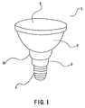
- Fig. 1 is a perspective view illustrating the light emitting element lamp.
- Fig. 2 is a sectional elevation view illustrating a portion of the light emitting element lamp.
- Fig. 3 is a schematic top view illustrating the light emitting element lamp with a translucent cover being removed therefrom. It is first to be noted that a following description is based on the assumption that the light emitting element lamp according to the present embodiment may be mounted instead of an existing reflective incandescent light bulb referred to as a so-called beam lamp, and has an outer appearance and dimensions substantially equivalent to those of the beam lamp.
- the beam lamp is suitable for spotlights used in various stores, floodlights for lighting buildings or signs, and lights at construction sites or the like.
- a light emitting element lamp 1 has an outer appearance similar to that of the existing beam lamp.
- the light emitting element lamp 1 includes a reflector 2, a cover portion 3, a base 4, and a front lens 5 as a translucent cover.
- the reflector 2 is formed as an integrally molded article of aluminum, for example.
- the reflector 2 is formed in a bowl shape so as to be widened from a base portion 2b toward an emission opening portion 2c with a reflecting surface 2a being provided on an inner surface side and an outer peripheral surface being exposed to an outside.
- the reflector 2 may be made of not only aluminum, but also a metal material or a resin material having good heat conductivity.
- the cover portion 3 is an integrally molded article of aluminum, for example, which is formed in a substantially cylindrical shape.
- the base portion 2b of the reflector 2 is fixed to one end of the cover portion 3, and the base 4 is fixed to the other end thereof.
- the base 4 is a standard E26 base.
- the base 4 is screwed into a lamp socket of a lighting equipment or apparatus when the light emitting element lamp 1 is mounted in the lighting equipment.
- the front lens 5 is attached to the reflector 2 via a seal so as to hermetically cover the opening portion 2c of the reflector 2.
- a collecting lens or a diffusing lens may be selected according to the intended use as the front lens 5.
- components of the existing beam lamp are directly used as the components (the reflector 2, the cover portion 3, the base 4, and the front lens 5) mentioned above.
- a light emitting element as a light source is provided in the base portion 2b of the reflector 2.
- the light emitting element is an LED chip 6.
- the LED chips 6 are mounted on a printed substrate 7 using chip-on-board technology. That is, 100 LED chips 6 are disposed in a matrix of 10 columns and 10 rows on a front surface of the printed substrate 7. A coating material is applied to surfaces of the LED chips 6.
- the printed substrate 7 is a substantially square flat plate of metal or an insulating material (see Fig. 3 ).
- a material having good heat conductivity and excellent in heat radiation property such as aluminum is preferably used.
- the printed substrate 7 is made of an insulating material, a ceramic material or a synthetic resin material having relatively good heat radiation property and excellent in durability may be used. In the case where the synthetic resin material is used, glass epoxy resin or the like may be employed, for example.
- the substrate 7 is bonded to a heat radiating member 8 with an adhesive.
- a material having good heat conductivity obtained by mixing a metal oxide or the like into a silicone resin adhesive is preferably used as the adhesive.
- the heat radiating member 8 is an integrally molded article of aluminum, and is formed in a substantially circular disc shape.
- the heat radiating member 8 has a flat mounting surface 8a on which the substrate 7 is to be mounted.
- a flange portion 8b is formed from the mounting surface 8a in an outer circumferential direction.
- the flange portion 8b of the heat radiating member 8 is formed on the inner surface side of the reflector 2, that is, in a shape along the reflecting surface 2a, and is thereby mounted on the reflector 2 in close surface contact therewith.
- the adhesive having good heat conductivity as described above is also preferably used to mount the flange portion 8b on the reflector 2. That is, the heat radiating member 8 forms a continuous surface with the reflecting surface 2a of the reflector 2.
- a lighting circuit 9 is housed in the cover portion 3.
- the lighting circuit 9 is used for lighting the LED chips 6.
- Components such as a capacitor and a transistor as a switching element are mounted on a circuit board of the lighting circuit 9.
- a lead wire extends from the lighting circuit 9 so as to be electrically connected to the printed substrate 7 and the base 4, not shown.
- An insulating protection tube 10 for electrically insulating the lighting circuit 9 is arranged around the lighting circuit 9.
- the lighting circuit 9 may be entirely housed within the cover portion 3, or may be partially housed within the cover portion 3 with a remaining portion being housed within the base 4.
- the lighting circuit 9 When the light emitting element lamp 1 is electrified by mounting the base 4 in a socket of a lighting equipment, the lighting circuit 9 is activated to supply power to the substrate 7.
- the LED chips 6 thereby emit light.
- the light emitted from the LED chips 6 mostly passes directly through the front lens 5 to be projected frontward.
- the light is partially reflected by the reflecting surface 2a of the reflector 2, and passes through the front lens 5 to be projected frontward. Meanwhile, heat generated from the LED chips 6 in association therewith is mainly conducted to the heat radiating member 8 through the adhesive from substantially the entire rear surface of the substrate 7.
- the heat is further conducted through the flange portion 8b of the heat radiating member 8 to the reflector 2 having a large heat radiation area in surface contact with the flange portion 8b, and is radiated therefrom.
- the respective members are thermally connected to each other as described above, so that a temperature rising of the substrate 7 can be suppressed by radiating the heat through the heat conducting path.
- the temperature rising of the substrate 7 on which the LED chips 6 are mounted can be effectively suppressed by use of the reflector 2. Since the substrate 7 is in surface contact with the heat radiating member 8, good heat conductivity will be achieved. Since the heat radiating member 8 is also in surface contact with the reflector 2, good heat conductivity will be also achieved. As a result, the heat radiation property can be improved. Furthermore, since the reflector 2 flares in a light emitting direction, the outer peripheral surface that produces a heat radiation effect has a large area, and is provided away from the lighting circuit 9 that is another heat generating source and requires thermal protection. Thus, it is effective to utilize the reflector 2 as a heat radiating element to suppress the temperature rising of the substrate 7.
- the heat radiating member 8 since the heat radiating member 8, particularly, the flange portion 8b has the shape along the reflecting surface 2a to form the continuous surface with the reflecting surface 2a of the reflector 2, the heat radiating member 8 is less likely to deteriorate a reflection effect of the reflecting surface 2a. Additionally, since the components of the existing so-called beam lamp can be used, the components can be shared between the light emitting element lamp and the existing beam lamp, so that the light emitting element lamp can be provided at a low cost.
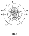
- a printed substrate 7-2 is a circular flat plate.
- the LED chips 6 are regularly mounted on the circular plate.
- the circular printed substrate 7-2 is disposed substantially concentrically with the heat radiating member 8 and the reflector 2 as shown in the drawing.
- the temperature rise of the printed substrate 7-2 can be substantially uniformly suppressed in addition to the effect described in the first embodiment.
- FIG. 5 is a sectional elevation view illustrating an essential portion of the light emitting element lamp according to the third embodiment.
- a heat radiating member 8-2 has a cap shape. The heat radiating member 8-2 is bonded to the base portion 2b of the reflector 2 with the adhesive with an outer peripheral surface 8-2b being in close surface contact with the base portion 2b.
- heat generated from the LED chips 6 is conducted to the heat radiating member 8-2 through the adhesive from substantially the entire rear surface of the substrate 7.
- the heat is further conducted through the outer peripheral surface 8-2b of the heat radiating member 8-2 to the reflector 2 having a large heat radiation area in surface contact with the outer peripheral surface 8-2b, and is radiated therefrom.
- the temperature rising of the substrate 7 can be thereby suppressed.
- the heat radiating member 8-2 forms a continuous surface with the reflecting surface 2a of the reflector 2 without projecting therefrom, the heat radiating member 8-2 does not deteriorate the reflection effect of the reflecting surface 2a.
- Fig. 6 is a sectional elevation view illustrating the light emitting element lamp according to the fourth embodiment.
- a heat radiating member 8-3 is formed in substantially the same shape as that of the reflector 2, and is mounted thereon so as to enclose a rim of the emission opening portion 2c of the reflector 2 from the inner side toward the outer side in a surface contact state.
- heat generated from the LED chips 6 is also conducted to the heat radiating member 8-3 through the adhesive from substantially the entire rear surface of the substrate 7.
- the heat is further conducted through an opening rim 8-3b of the heat radiating member 8-3 to the rim of the emission opening portion 2c of the reflector 2 in surface contact with the opening rim 8-3b, is conducted to the outer peripheral surface of the reflector 2 having a large heat radiation area, and is effectively radiated therefrom.
- the temperature rising of the substrate 7 can be thereby suppressed.
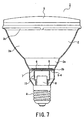
- Fig. 7 is a sectional elevation view illustrating the light emitting element lamp according to the fifth embodiment, which does not have a recessed portion on a back surface side of a heat radiating member and does not fall within the scope of the claims.
- a heat radiating member 8-4 is formed integrally with the base portion 2b of the reflector 2. According to the present embodiment, heat generated from the LED chips 6 is conducted to the heat radiating member 8-4 through the adhesive from substantially the entire rear surface of the substrate 7. The heat is further directly conducted to the reflector 2 having a large heat radiation area and is radiated therefrom. The temperature rising of the substrate 7 can be thereby suppressed. Since the heat radiating member 8-4 is integrated with the reflecting surface 2a of the reflector 2 and forms a continuous surface with the reflecting surface 2a without projecting therefrom, the heat radiating member 8-4 does not deteriorate the reflection effect of the reflecting surface 2a.
- a light emitting element lamp according to a sixth embodiment which does not have a recessed portion on a back surface side of a heat radiating member and does not fall within the scope of the claims, will be described with reference to Figs. 8 to 11 .
- Fig. 8 is a sectional view illustrating a light emitting element lamp (Example 1), which does not have a recessed portion on a back surface side of a heat radiating member and does not fall within the scope of the claims.
- Fig. 9 is a plan view illustrating the light emitting element lamp with a first reflector being removed therefrom.
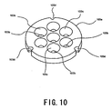
- Fig. 10 is a perspective view illustrating a second reflector.
- Fig. 8 is a sectional view illustrating a light emitting element lamp (Example 1), which does not have a recessed portion on a back surface side of a heat radiating member and does not fall within the scope of the claims.
- Fig. 9 is a plan view illustrating the light emitting element lamp with a first reflect
- FIG. 11 is a sectional view illustrating a light emitting element lamp (Example 2) , which does not have a recessed portion on a back surface side of a heat radiating member and does not fall within the scope of the claims.
- the light emitting element lamp according to the present embodiment is a lamp referred to as a so-called beam lamp in a similar manner to the first embodiment.
- the heat radiating member is formed integrally with the reflector in a similar manner to the fifth embodiment.
- a light emitting element lamp 101 has an outer appearance similar to that of the existing beam lamp, and has a waterproof function to be appropriately used outdoors.
- the light emitting element lamp 101 includes a heat-conductive first reflector 102, a light source portion 103, a second reflector 103a, a light emitting element 104, a heat-conductive cover 105, an insulating cover 106, a base 107 and a front lens 108 as a translucent cover.
- the first reflector 102 is an integrally molded article of aluminum, for example, and white acrylic baking paint is applied thereon.
- the first reflector 102 is formed in a bottomed bowl shape so as to flare (be widened) from a base portion 102a toward an emission opening portion 102b with an outer peripheral surface being exposed to an outside.
- a bottom wall of an inner peripheral surface has a flat surface, and a heat radiating member 102c is formed integrally therewith. Meanwhile, a bottom wall rim of the outer peripheral surface forms a ring-shaped connection portion 102d to be connected to the heat-conductive cover 105 described below.
- Three threaded through holes are formed in the bottom wall with an interval of about 120 degrees therebetween.
- the first reflector 102 may be made of not only aluminum, but also a metal material or a resin material having good heat conductivity. Furthermore, alumite treatment is preferably applied to the inner peripheral surface of the first reflector 102. By applying the alumite treatment, a heat radiation effect of the first reflector 102 can be improved. When the alumite treatment is applied thereto, although a reflection effect of the inner peripheral surface of the first reflector 102 is reduced, the reduction in reflection effect does not degrade the performance of the light emitting element lamp as the second reflector 103a described below is separately provided. Further, in order to improve the reflection effect of the first reflector 102, the inner peripheral surface may be mirror-finished or the like.
- the light source portion 103 is provided on the bottom wall of the first reflector 102.
- the light source portion (unit or section) 103 includes a substrate 109 and the light emitting elements 104 mounted on the substrate 109.
- the light emitting elements 104 are LED chips, which are mounted on the substrate 109 using chip-on-board technology. That is, a plurality of LED chips are disposed in a matrix on a front surface of the substrate 109. A coating material is applied to surfaces of the LED chips.
- the substrate 109 is a substantially circular flat plate made of metal, for example, a material having good heat conductivity and excellent in heat radiation property such as aluminum.
- a ceramic material or a synthetic resin material having relatively good heat radiation property and excellent in durability can be applied.
- glass epoxy resin or the like may be employed, for example.
- the substrate 109 is mounted on the heat radiating member 102c formed on the bottom wall of the first reflector 102 in close surface contact therewith.
- an adhesive may be used to mount the substrate 109.
- the adhesive a material having good heat conductivity obtained by mixing a metal oxide or the like into a silicone resin adhesive is preferably used.
- the substrate 109 and the heat radiating member 102c may not be in full surface contact, but may be in partial surface contact with each other.
- the second reflector 103a made of white polycarbonate, ASA resin or the like is mounted on the front surface of the substrate 109.
- the second reflector 103a enables effective light emission by controlling distribution of light emitted from each of the LED chips.
- the second reflector 103a has a circular disc shape.
- a plurality of incident openings 103b are defined by a ridge line to be formed in the second reflector 103a. Each of the incident openings 103b of the second reflector 103a is disposed so as to face each of the LED chips of the substrate, 109.
- a substantially bowl-shaped reflecting surface 103c flaring from each of the incident openings 103b in an emission direction, that is, toward the ridge line is formed in the second reflector 103a with respect to each of the incident openings 103b.
- Three cutouts 103d to which screws are inserted and engaged are formed in an outer peripheral portion of the second reflector 103a with an interval of about 120 degrees therebetween.
- the heat-conductive cover 105 is made of aluminum die casting. White acrylic baking paint is applied thereon.
- the heat-conductive cover 105 is formed in a substantially cylindrical shape tapered to a distal end continuously from the outer peripheral surface of the first reflector 102. The length and thickness of the cover 105 may be appropriately determined in consideration of the heat radiation effect or the like.
- a connection portion 105a of the cover 105 with the first reflector 102 has a ring shape with a predetermined width (see Fig. 2 ).
- the connection portion 102d of the first reflector 102 is formed so as to face the connection portion 105a.
- the connection portions 102d and 105a are thermally connected to each other in a surface contact state.
- a ring-shaped groove is formed in the connection portion 105a.
- An O-ring 110 made of synthetic rubber or the like is fitted into the groove. Three threaded holes 111 are formed on an inner side of the O-ring 110 with an interval of about 120 degrees therebetween.
- the insulating cover 106 molded from PBT resin is provided along the shape of the heat-conductive cover 105 on an inner side of the heat-conductive cover 105.
- the insulating cover 106 is connected to the heat-conductive cover 105 on one end side so as to project from the heat-conductive cover 105 on the other end side.
- the base 107 is fixed to a projecting portion 106a.
- the base 107 is a standard E26 base.
- the base 107 is screwed into a lamp socket of a lighting equipment when the light emitting element lamp 101 is mounted in the lighting equipment.
- An air outlet 106b is formed in the projecting portion 106a.
- the air outlet 106b is a small hole for reducing a pressure when an internal pressure in the insulating cover 106 is increased.
- a lighting circuit 112 is housed in the insulating cover 106.
- the lighting circuit 112 is used for controlling the lighting of the LED chips, and includes components such as a capacitor and a transistor as a switching element.
- the lighting circuit 112 is mounted on a circuit board.
- the circuit board has a substantially T-shape and is housed longitudinally in the insulating cover 106. A narrow space can be thereby effectively utilized for mounting the circuit board therein.
- a lead wire 112a extends from the lighting circuit 112 to be electrically connected to the substrate 109 of the light source portion 103 through a lead wire insertion hole 112b formed in the heat radiating member 102c.
- the lighting circuit 112 is also electrically connected to the base 107.
- the lighting circuit 112 may be entirely housed within the insulating cover 106 or may be partially housed within the insulating cover 106 with a remaining portion being housed within the base 107.
- a filling material 113 fills the insulating cover 106 so as to cover the lighting circuit 112.
- the filling material 113 is made of silicone resin and has elasticity, insulating property and heat conductivity.
- a liquid filling material 113 is first injected from above the insulating cover 106.
- the filling material 113 is injected to reach the level at a top end portion of the insulating cover 106.
- the filling material 113 is then hardened and stabilized in a high temperature atmosphere.
- the front lens 108 is attached to the first reflector 102 via a silicone resin packing or seal so as to hermetically cover the emission opening portion 102b of the first reflector 102.
- a collecting lens or a diffusing lens may be appropriately selected according to the intended use as the front lens 108.
- the heat-conductive first reflector 102 and the heat-conductive cover 105 will be connected in the following manner.
- the connection portion 102d of the first reflector 102 is disposed so as to face the connection portion 105a of the heat-conductive cover 105.
- the substrate 109 is arranged on the heat radiating member 102c of the first reflector 102, and the second reflector 103a is overlapped thereon.
- screws 114 are screwed into the threaded holes 111 of the heat-conductive cover 105 through the cutouts 103d of the second reflector 103a and the threaded through holes of the first reflector 102.
- the heat-conductive first reflector 102 is thereby fixed to the heat-conductive cover 105.
- a bottom end of the second reflector 103a presses the front surface of the substrate 109, so that the second reflector 103a and the substrate 109 are fixed to the bottom wall of the first reflector 102.
- the O-ring 110 is elastically deformed between the connection portion 105a and the connection portion 102d to thereby connect the connection portions 105a and 102d in an airtight state. That is, the inner side of the O-ring 110 is maintained in an airtight state.
- the wiring for electrical connection between the lighting circuit 112 and the substrate 109 on which the LED chips are mounted by the lead wire 112a is done on the inner side of the O-ring 110.
- the lighting circuit 112 is activated to supply power to the substrate 109.
- the LED chips thereby emit light.
- Distribution of the light emitted from each of the LED chips is controlled by each of the reflecting surfaces 103c of the second reflector 103a.
- the light is also reflected by the first reflector 102, and passes through the front lens 108 to be projected frontward. Heat generated from the LED chips in association therewith is conducted to the heat radiating member 102c from a substantially entire rear surface of the substrate 109.
- the heat is further conducted to the first reflector 102 having a large heat radiation area. Furthermore, the heat is conducted to the connection portion 105a of the heat conductive cover 5 from the connection portion 102d of the first reflector 102, and is conducted to the entire heat conductive cover 105.
- the respective members are thermally connected to each other as described above, so that a temperature rising of the substrate 109 can be suppressed by radiating the heat through the heat conducting path. Meanwhile, the heat generated from the lighting circuit 112 is conducted to the first reflector 102 via the filling material 113 and is radiated therefrom. The heat is then transferred to the base 107, which is then conducted to the lamp socket of the lighting equipment or the like, and is radiated therefrom.
- the front lens 108 is attached to the emission opening portion 102b of the first reflector 102 via the packing.
- the O-ring 110 is provided between the connection portion 102d of the first reflector 102 and the connection portion 105a of the heat-conductive cover 105a.
- the lighting circuit 112 is covered by the filling material 113. Accordingly, the electric insulating property is maintained, and a weather-resistance and rain-proof function is provided.
- the light emitting element lamp 101 is thereby appropriately used in outdoors. If the lighting circuit components function abnormally and the capacitor is damaged or blown to increase the internal pressure in the insulating cover 106, a secondary damage may be caused because of employment of the sealed structure for the above purpose. However, the increasing pressure inside the insulating cover 106 can be discharged through the air outlet 106b.
- the temperature rising of the substrate 109 on which the light emitting elements 104 are mounted can be effectively suppressed by use of the heat conductive first reflector 102 and the heat-conductive cover 105 Since the first reflector 102 flares toward the emission opening portion 102b, the outer peripheral surface that produces a heat radiation effect has a large area, and the heat radiation effect is effectively improved. Since the heatconductive first reflector 102 is in surface contact with the heat-conductive cover 105, good heat conductivity is achieved. Furthermore, the light distribution can be controlled with respect to each of the LED chips by each of the reflecting surfaces 103c of the second reflector 103a, so that the desired optical processing could be performed.
- the O-ring 110 is provided between the connection portion 102d of the first reflector 102 and the connection portion 105a of the heat-conductive cover 105 to maintain the sealability, the waterproof function can be maintained and the power supply path to the light source portion 103 can also be ensured with the simple configuration. Additionally, since the components of the existing so-called beam lamp can be used, the components will be shared between the light emitting element lamp and the existing beam lamp. Accordingly, the light emitting element lamp can be provided at a low cost.
- Fig. 11 shows a configuration in which the second reflector in the first example is not provided according to the present example.
- the same portions as those of the first example are assigned with the same reference numerals and duplicated description is omitted herein.
- the heat generated from the LED chips is also conducted to the heat radiating member 102c from substantially the entire rear surface of the substrate 109 and is further conducted to the first reflector 102 having a large heat radiation area in a manner similar to the first example, thus performing the effective heat radiation.
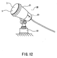
- a garden light is shown as a lighting equipment 20.
- the lighting equipment 20 includes an apparatus body 21 and a base 22 on which the apparatus body 21 is mounted.
- a socket 23 is provided in the apparatus body 21.
- the base 4 of the light emitting element lamp 1 is screwed into the socket 23.
- the lighting equipment or apparatus 20 is installed by fixing the base 22 to the ground or the like.
- the apparatus body 21 can be changed in direction relative to the base 22, so that a light emitting direction can be changed to any direction.
- the heat generated from the substrate by lighting the light emitting element can be effectively radiated by using the relatively large outer peripheral surface of the reflector having the flaring shape toward the emission opening portion. Accordingly, the temperature rising of the light emitting element lamp can be effectively suppressed.
Landscapes
- Engineering & Computer Science (AREA)
- General Engineering & Computer Science (AREA)
- Microelectronics & Electronic Packaging (AREA)
- Physics & Mathematics (AREA)
- Optics & Photonics (AREA)
- Arrangement Of Elements, Cooling, Sealing, Or The Like Of Lighting Devices (AREA)
- Led Device Packages (AREA)
- Non-Portable Lighting Devices Or Systems Thereof (AREA)
Claims (2)
- Lichtemissionselementlampe (1) mit
einem wärmeleitenden Reflektor (2), der an einer Endseite mit einem Emissionsöffnungsabschnitt und an einer anderen Endseite mit einem inneren flachen wärmeabstrahlenden Teil (8) und einem ausgesparten Abschnitt auf einer Rückflächenseite des wärmeabstrahlenden Elements (8) versehen ist und der derart ausgebildet ist, dass er sich in Richtung des Emissionsöffnungsabschnitts von der anderen Endseite aus aufweitet, und der eine Reflektionsoberfläche (2a) hat, die auf einer Innenseite und einer Außenumfangsfläche, die gegenüber dem Äußeren freiliegt, vorgesehen ist,
einem Abdeckungsabschnitt (3) mit einem an der anderen Endseite des Reflektors (2) derart befestigten einen Ende, dass er mit dem ausgesparten Abschnitt des Reflektors (2) verbunden ist,
einer an dem anderen Ende des Abdeckungsabschnitts (3) befestigten Basis (4), einem Drucksubstrat (7), das mit einem Lichtemissionselement (6) versehen ist und das an dem wärmeabstrahlenden Teil (8) mit einer Substratoberfläche, die thermisch mit der inneren flachen Oberfläche (8a) des wärmeabstrahlenden Teils (8) in einem Oberflächenkontaktzustand thermisch verbunden ist, befestigt ist, und
einem Beleuchtungskreis (9), der in einem derart in dem Abdeckungsabschnitt (3) und dem Reflektor (2) ausgebildeten Bereich getrennt von der Außenfläche des wärmeabstrahlenden Teils (8) des Reflektors (2) untergebracht ist, um das Lichtemissionselement zu erleuchten. - Beleuchtungsgerät (2) mit
einem Gerätekörper (21) mit einer Fassung (23), und
einer Lichtemissionselementlampe (1) gemäß Anspruch 1 zum Anbringen in der Fassung (23) des Gerätekörpers (21).
Priority Applications (1)
| Application Number | Priority Date | Filing Date | Title |
|---|---|---|---|
| EP12188866.3A EP2562469A3 (de) | 2007-10-16 | 2008-10-15 | Lampe mit lichtemittierendem Element und Beleuchtungseinheit |
Applications Claiming Priority (3)
| Application Number | Priority Date | Filing Date | Title |
|---|---|---|---|
| JP2007268769 | 2007-10-16 | ||
| JP2008198625A JP4569683B2 (ja) | 2007-10-16 | 2008-07-31 | 発光素子ランプ及び照明器具 |
| PCT/JP2008/068625 WO2009051128A1 (ja) | 2007-10-16 | 2008-10-15 | 発光素子ランプ及び照明器具 |
Related Child Applications (2)
| Application Number | Title | Priority Date | Filing Date |
|---|---|---|---|
| EP12188866.3A Division EP2562469A3 (de) | 2007-10-16 | 2008-10-15 | Lampe mit lichtemittierendem Element und Beleuchtungseinheit |
| EP12188866.3 Division-Into | 2012-10-17 |
Publications (4)
| Publication Number | Publication Date |
|---|---|
| EP2199658A1 EP2199658A1 (de) | 2010-06-23 |
| EP2199658A4 EP2199658A4 (de) | 2011-06-29 |
| EP2199658B1 EP2199658B1 (de) | 2012-11-28 |
| EP2199658B9 true EP2199658B9 (de) | 2013-03-27 |
Family
ID=40567390
Family Applications (2)
| Application Number | Title | Priority Date | Filing Date |
|---|---|---|---|
| EP08838942A Not-in-force EP2199658B9 (de) | 2007-10-16 | 2008-10-15 | Lampe mit lichtemittierendem element und beleuchtungseinheit |
| EP12188866.3A Withdrawn EP2562469A3 (de) | 2007-10-16 | 2008-10-15 | Lampe mit lichtemittierendem Element und Beleuchtungseinheit |
Family Applications After (1)
| Application Number | Title | Priority Date | Filing Date |
|---|---|---|---|
| EP12188866.3A Withdrawn EP2562469A3 (de) | 2007-10-16 | 2008-10-15 | Lampe mit lichtemittierendem Element und Beleuchtungseinheit |
Country Status (5)
| Country | Link |
|---|---|
| US (2) | US8384275B2 (de) |
| EP (2) | EP2199658B9 (de) |
| JP (1) | JP4569683B2 (de) |
| CN (1) | CN101828069A (de) |
| WO (1) | WO2009051128A1 (de) |
Families Citing this family (80)
| Publication number | Priority date | Publication date | Assignee | Title |
|---|---|---|---|---|
| US7758223B2 (en) | 2005-04-08 | 2010-07-20 | Toshiba Lighting & Technology Corporation | Lamp having outer shell to radiate heat of light source |
| JP4569683B2 (ja) | 2007-10-16 | 2010-10-27 | 東芝ライテック株式会社 | 発光素子ランプ及び照明器具 |
| JP5353216B2 (ja) | 2008-01-07 | 2013-11-27 | 東芝ライテック株式会社 | Led電球及び照明器具 |
| CN101978209A (zh) * | 2008-06-27 | 2011-02-16 | 东芝照明技术株式会社 | 发光元件灯以及照明设备 |
| JP5333758B2 (ja) | 2009-02-27 | 2013-11-06 | 東芝ライテック株式会社 | 照明装置および照明器具 |
| JP2011003341A (ja) * | 2009-06-17 | 2011-01-06 | Wun Song Hu | Ledやsmdled電球及び電灯のハレーション消去且つ均一光と増光及び射角調整可能の構造 |
| JP5348410B2 (ja) | 2009-06-30 | 2013-11-20 | 東芝ライテック株式会社 | 口金付ランプおよび照明器具 |
| WO2011010535A1 (ja) * | 2009-07-22 | 2011-01-27 | 帝人株式会社 | Led照明具 |
| JP2011049527A (ja) | 2009-07-29 | 2011-03-10 | Toshiba Lighting & Technology Corp | Led照明装置 |
| EP2341277B1 (de) * | 2009-09-09 | 2013-06-19 | Panasonic Corporation | Birnenförmige lampe und beleuchtungsvorrichtung |
| JP5601512B2 (ja) | 2009-09-14 | 2014-10-08 | 東芝ライテック株式会社 | 発光装置および照明装置 |
| US20110062868A1 (en) * | 2009-09-14 | 2011-03-17 | Domagala Thomas W | High luminous output LED lighting devices |
| KR101414640B1 (ko) * | 2009-09-23 | 2014-07-03 | 엘지전자 주식회사 | 방열 장치 |
| JP2011071242A (ja) | 2009-09-24 | 2011-04-07 | Toshiba Lighting & Technology Corp | 発光装置及び照明装置 |
| US9713211B2 (en) | 2009-09-24 | 2017-07-18 | Cree, Inc. | Solid state lighting apparatus with controllable bypass circuits and methods of operation thereof |
| US10264637B2 (en) | 2009-09-24 | 2019-04-16 | Cree, Inc. | Solid state lighting apparatus with compensation bypass circuits and methods of operation thereof |
| US8901845B2 (en) | 2009-09-24 | 2014-12-02 | Cree, Inc. | Temperature responsive control for lighting apparatus including light emitting devices providing different chromaticities and related methods |
| US9464801B2 (en) * | 2009-09-25 | 2016-10-11 | Cree, Inc. | Lighting device with one or more removable heat sink elements |
| US8777449B2 (en) | 2009-09-25 | 2014-07-15 | Cree, Inc. | Lighting devices comprising solid state light emitters |
| US8602579B2 (en) | 2009-09-25 | 2013-12-10 | Cree, Inc. | Lighting devices including thermally conductive housings and related structures |
| JP2011091033A (ja) | 2009-09-25 | 2011-05-06 | Toshiba Lighting & Technology Corp | 発光モジュール、電球形ランプおよび照明器具 |
| US8678618B2 (en) | 2009-09-25 | 2014-03-25 | Toshiba Lighting & Technology Corporation | Self-ballasted lamp having a light-transmissive member in contact with light emitting elements and lighting equipment incorporating the same |
| US9285103B2 (en) * | 2009-09-25 | 2016-03-15 | Cree, Inc. | Light engines for lighting devices |
| US8324789B2 (en) | 2009-09-25 | 2012-12-04 | Toshiba Lighting & Technology Corporation | Self-ballasted lamp and lighting equipment |
| CN102032481B (zh) | 2009-09-25 | 2014-01-08 | 东芝照明技术株式会社 | 附带灯口的照明灯及照明器具 |
| US9068719B2 (en) | 2009-09-25 | 2015-06-30 | Cree, Inc. | Light engines for lighting devices |
| JP2011076880A (ja) * | 2009-09-30 | 2011-04-14 | Toshiba Lighting & Technology Corp | 電球形ランプおよび照明器具 |
| JP5558273B2 (ja) * | 2009-11-05 | 2014-07-23 | ミサワホーム株式会社 | Led照明灯 |
| DE102009053957A1 (de) * | 2009-11-19 | 2011-06-01 | Osram Gesellschaft mit beschränkter Haftung | Reflektor für eine Leuchtvorrichtung und Leuchtvorrichtung |
| USD673322S1 (en) | 2009-11-19 | 2012-12-25 | Cree, Inc. | Light engine for a lighting device |
| CN102102816A (zh) * | 2009-12-22 | 2011-06-22 | 富准精密工业(深圳)有限公司 | 发光二极管灯具 |
| US8613530B2 (en) | 2010-01-11 | 2013-12-24 | General Electric Company | Compact light-mixing LED light engine and white LED lamp with narrow beam and high CRI using same |
| DE102010001974A1 (de) * | 2010-02-16 | 2011-08-18 | Osram Gesellschaft mit beschränkter Haftung, 81543 | Leuchtmittel sowie Verfahren zu dessen Herstellung |
| JP5257622B2 (ja) | 2010-02-26 | 2013-08-07 | 東芝ライテック株式会社 | 電球形ランプおよび照明器具 |
| US8729781B2 (en) * | 2010-03-03 | 2014-05-20 | Koninklijke Philips N.V. | Electric lamp having reflector for transferring heat from light source |
| TWM387195U (en) * | 2010-04-08 | 2010-08-21 | Ge Investment Co Ltd | LED illumination apparatus |
| US8476836B2 (en) | 2010-05-07 | 2013-07-02 | Cree, Inc. | AC driven solid state lighting apparatus with LED string including switched segments |
| JP4854798B2 (ja) * | 2010-05-31 | 2012-01-18 | シャープ株式会社 | 照明装置 |
| JP5427294B2 (ja) * | 2010-06-07 | 2014-02-26 | アイリスオーヤマ株式会社 | Ledランプ |
| JP5609332B2 (ja) * | 2010-07-05 | 2014-10-22 | 住友ベークライト株式会社 | 光源装置および照明器具 |
| US8789969B2 (en) | 2010-08-17 | 2014-07-29 | GE Lighting Solutions, LLC | Compact LED light engine with reflector cups and highly directional lamps using same |
| US8757852B2 (en) | 2010-10-27 | 2014-06-24 | Cree, Inc. | Lighting apparatus |
| USD683063S1 (en) | 2010-10-27 | 2013-05-21 | Cree, Inc. | Lighting fixture |
| JP5677806B2 (ja) * | 2010-11-02 | 2015-02-25 | ローム株式会社 | Led電球 |
| US9188292B2 (en) * | 2010-11-17 | 2015-11-17 | Light & Motion Industries | Diver's underwater light for selecting between two types of light |
| US9863622B1 (en) | 2010-11-17 | 2018-01-09 | Light & Motion Industries | Underwater lights for divers |
| JP5666882B2 (ja) * | 2010-11-18 | 2015-02-12 | 株式会社小糸製作所 | ハイビーム用灯具ユニット |
| EP2463576A3 (de) * | 2010-12-10 | 2014-03-19 | Toshiba Lighting & Technology Corporation | Montagevorrichtung für Abdeckungselement, sockelbefestigte Lampe und Beleuchtungskörper |
| EP2667090B1 (de) * | 2011-01-21 | 2016-03-09 | Citizen Electronics Co., Ltd. | Beleuchtungsvorrichtung und herstellungsverfahren einer halterung einer beleuchtungsvorrichtung |
| JP5015357B1 (ja) | 2011-01-27 | 2012-08-29 | パナソニック株式会社 | 光源装置 |
| USD683890S1 (en) | 2011-04-11 | 2013-06-04 | Cree, Inc. | Lighting fixture |
| US8919999B2 (en) | 2011-04-29 | 2014-12-30 | Joy Mm Delaware, Inc. | Flat panel light with clear potting material |
| US9839083B2 (en) | 2011-06-03 | 2017-12-05 | Cree, Inc. | Solid state lighting apparatus and circuits including LED segments configured for targeted spectral power distribution and methods of operating the same |
| CN202176934U (zh) * | 2011-07-20 | 2012-03-28 | 深圳市众明半导体照明有限公司 | 一种led灯具及照明设备 |
| US8742671B2 (en) | 2011-07-28 | 2014-06-03 | Cree, Inc. | Solid state lighting apparatus and methods using integrated driver circuitry |
| KR101911762B1 (ko) * | 2011-08-09 | 2018-10-26 | 엘지이노텍 주식회사 | 조명 장치 |
| WO2013024557A1 (ja) * | 2011-08-12 | 2013-02-21 | パナソニック株式会社 | Ledランプおよび照明装置 |
| CN103765078A (zh) * | 2011-08-26 | 2014-04-30 | Lg伊诺特有限公司 | 照明装置 |
| TWM442454U (en) * | 2011-11-11 | 2012-12-01 | Yi-Ming Chen | Light emitting diode bulb |
| CN103322438A (zh) * | 2012-03-22 | 2013-09-25 | 李文雄 | 大功率发光二极管投光灯及其制造方法 |
| JP5073865B2 (ja) * | 2012-05-18 | 2012-11-14 | シャープ株式会社 | 電球型の照明装置 |
| JP5468662B2 (ja) * | 2012-10-02 | 2014-04-09 | シャープ株式会社 | 電球型の照明装置 |
| US9188312B2 (en) * | 2013-03-14 | 2015-11-17 | GE Lighting Solutions, LLC | Optical system for a directional lamp |
| US9041303B2 (en) * | 2013-03-29 | 2015-05-26 | Posco Led Company Ltd. | AC LED lighting apparatus |
| US9157625B2 (en) * | 2013-04-23 | 2015-10-13 | P.T. Padma Soode Indonesia | Lightweight lighting fixture with improved heat management configuration |
| US9103510B2 (en) * | 2013-05-23 | 2015-08-11 | Feit Electric Company, Inc. | Hard-pressed glass light emitting diode flood lamp |
| JP5620595B2 (ja) * | 2014-02-14 | 2014-11-05 | シャープ株式会社 | 電球型の照明装置 |
| JP5632979B2 (ja) * | 2014-02-28 | 2014-11-26 | シャープ株式会社 | 電球型の照明装置 |
| CA2946133A1 (en) * | 2014-04-18 | 2015-10-22 | Butterfly Network, Inc. | Ultrasonic transducers in complementary metal oxide semiconductor (cmos) wafers and related apparatus and methods |
| JP6349186B2 (ja) * | 2014-07-25 | 2018-06-27 | 日立アプライアンス株式会社 | 照明装置 |
| KR102209034B1 (ko) * | 2014-07-30 | 2021-01-28 | 엘지이노텍 주식회사 | 발광 모듈 |
| JP6469402B2 (ja) * | 2014-09-30 | 2019-02-13 | 信越ポリマー株式会社 | ライト部材 |
| USD763475S1 (en) * | 2015-03-24 | 2016-08-09 | Green Creative Ltd. | Low-profile LED lightbulb |
| USD764077S1 (en) * | 2015-03-24 | 2016-08-16 | Green Creative Ltd | Low-profile LED lightbulb |
| USD763474S1 (en) * | 2015-03-24 | 2016-08-09 | Green Creative Ltd. | Low-profile LED lightbulb |
| US10288266B2 (en) | 2015-05-18 | 2019-05-14 | Feit Electric Company, Inc. | Adjustable recessed light fixture |
| JP6179821B2 (ja) * | 2015-08-19 | 2017-08-16 | 日本発條株式会社 | 照明器具 |
| US10448503B1 (en) * | 2018-05-07 | 2019-10-15 | Light & Motion Industries | Coplaner LED array and driver assembly |
| CN111536442A (zh) * | 2020-06-22 | 2020-08-14 | 晋江万代好光电照明有限公司 | 一种led灯具及其生产工艺 |
| DE102024108625A1 (de) * | 2023-03-27 | 2024-10-02 | Nichia Corporation | Lichtemittierende vorrichtung |
Family Cites Families (180)
| Publication number | Priority date | Publication date | Assignee | Title |
|---|---|---|---|---|
| US356107A (en) * | 1887-01-18 | Ella b | ||
| US534665A (en) * | 1895-02-26 | Method of casting projectiles | ||
| US534038A (en) * | 1895-02-12 | Dynamo-electric machine | ||
| US1972790A (en) | 1932-07-15 | 1934-09-04 | Crouse Hinds Co | Electric hand lamp |
| JPS5752706Y2 (de) | 1976-12-30 | 1982-11-16 | ||
| GB1601461A (en) | 1977-05-21 | 1981-10-28 | Amp Inc | Electrical junction box |
| JPS57152706A (en) | 1981-03-17 | 1982-09-21 | T C Denshi Kk | Antenna |
| JPS58150163U (ja) | 1982-03-31 | 1983-10-07 | 日本精機株式会社 | 積算計の照明装置 |
| US4503360A (en) | 1982-07-26 | 1985-03-05 | North American Philips Lighting Corporation | Compact fluorescent lamp unit having segregated air-cooling means |
| JPS6039656U (ja) | 1983-08-24 | 1985-03-19 | 池田物産株式会社 | シ−トの物品収納構造 |
| JPH071374B2 (ja) | 1984-03-06 | 1995-01-11 | 株式会社ニコン | 光源装置 |
| JPS6135216A (ja) | 1984-07-27 | 1986-02-19 | Sony Corp | 金属外観ある一体成形品の製造方法 |
| JPS62190366U (de) | 1986-05-24 | 1987-12-03 | ||
| JPS63102265A (ja) | 1986-10-20 | 1988-05-07 | Agency Of Ind Science & Technol | 半導体装置の製造方法 |
| US4939420A (en) | 1987-04-06 | 1990-07-03 | Lim Kenneth S | Fluorescent reflector lamp assembly |
| JPH01206505A (ja) | 1988-02-12 | 1989-08-18 | Toshiba Corp | けい光ランプ装置 |
| JPH0291105U (de) | 1988-12-28 | 1990-07-19 | ||
| USD356107S (en) | 1992-05-15 | 1995-03-07 | Fujitsu Limited | Developing cartridge for copier |
| JP3121916B2 (ja) | 1992-06-25 | 2001-01-09 | 矢橋工業株式会社 | 石灰焼結体の製造方法 |
| JP2662488B2 (ja) | 1992-12-04 | 1997-10-15 | 株式会社小糸製作所 | 自動車用灯具における前面レンズ脚部とシール溝間のシール構造 |
| US5327332A (en) | 1993-04-29 | 1994-07-05 | Hafemeister Beverly J | Decorative light socket extension |
| US5632551A (en) | 1994-07-18 | 1997-05-27 | Grote Industries, Inc. | LED vehicle lamp assembly |
| US5537301A (en) | 1994-09-01 | 1996-07-16 | Pacific Scientific Company | Fluorescent lamp heat-dissipating apparatus |
| US5585697A (en) | 1994-11-17 | 1996-12-17 | General Electric Company | PAR lamp having an integral photoelectric circuit arrangement |
| US6465743B1 (en) | 1994-12-05 | 2002-10-15 | Motorola, Inc. | Multi-strand substrate for ball-grid array assemblies and method |
| US5587757A (en) | 1995-02-15 | 1996-12-24 | Eastman Kodak Company | Camera access door interlock mechanism |
| EP0835408B1 (de) * | 1995-06-29 | 2001-08-22 | Siemens Microelectronics, Inc. | Gezielte beleuchtung unter verwendung der tir-technologie |
| US6095668A (en) | 1996-06-19 | 2000-08-01 | Radiant Imaging, Inc. | Incandescent visual display system having a shaped reflector |
| US5785418A (en) | 1996-06-27 | 1998-07-28 | Hochstein; Peter A. | Thermally protected LED array |
| US5857767A (en) | 1996-09-23 | 1999-01-12 | Relume Corporation | Thermal management system for L.E.D. arrays |
| JPH1125919A (ja) | 1997-07-04 | 1999-01-29 | Moriyama Sangyo Kk | 電球装置および照明装置 |
| US5947588A (en) | 1997-10-06 | 1999-09-07 | Grand General Accessories Manufacturing Inc. | Light fixture with an LED light bulb having a conventional connection post |
| JP2000083343A (ja) | 1998-09-03 | 2000-03-21 | Mitsubishi Electric Corp | モーターフレーム及びモーターフレームの製造方法 |
| DE69936375T2 (de) | 1998-09-17 | 2008-02-28 | Koninklijke Philips Electronics N.V. | Led-leuchte |
| JP3753291B2 (ja) | 1998-09-30 | 2006-03-08 | 東芝ライテック株式会社 | 電球形蛍光ランプ |
| JP2000173330A (ja) | 1998-12-08 | 2000-06-23 | Nissei Denki Kk | 光源装置 |
| US6502968B1 (en) | 1998-12-22 | 2003-01-07 | Mannesmann Vdo Ag | Printed circuit board having a light source |
| US6186646B1 (en) | 1999-03-24 | 2001-02-13 | Hinkley Lighting Incorporated | Lighting fixture having three sockets electrically connected and mounted to bowl and cover plate |
| JP2000294434A (ja) | 1999-04-02 | 2000-10-20 | Hanshin Electric Co Ltd | 内燃機関用点火コイル |
| US6161910A (en) | 1999-12-14 | 2000-12-19 | Aerospace Lighting Corporation | LED reading light |
| JP2001243809A (ja) | 2000-02-28 | 2001-09-07 | Mitsubishi Electric Lighting Corp | Led電球 |
| US6814470B2 (en) * | 2000-05-08 | 2004-11-09 | Farlight Llc | Highly efficient LED lamp |
| US7122900B2 (en) | 2000-06-26 | 2006-10-17 | Renesas Technology Corp. | Semiconductor device and method manufacturing the same |
| JP2002075011A (ja) | 2000-08-30 | 2002-03-15 | Matsushita Electric Ind Co Ltd | 管 球 |
| US6517217B1 (en) | 2000-09-18 | 2003-02-11 | Hwa Hsia Glass Co., Ltd. | Ornamental solar lamp assembly |
| GB0027330D0 (en) * | 2000-11-09 | 2000-12-27 | Ncr Int Inc | Disseminating consumer information |
| JP2002280617A (ja) * | 2001-03-19 | 2002-09-27 | Matsushita Electric Ind Co Ltd | 照明装置 |
| US6598996B1 (en) | 2001-04-27 | 2003-07-29 | Pervaiz Lodhie | LED light bulb |
| JP3940596B2 (ja) * | 2001-05-24 | 2007-07-04 | 松下電器産業株式会社 | 照明光源 |
| CN2489462Y (zh) | 2001-06-17 | 2002-05-01 | 广东伟雄集团有限公司 | 带镶嵌条的节能灯 |
| JP4674418B2 (ja) | 2001-06-29 | 2011-04-20 | パナソニック株式会社 | 照明装置 |
| JP4076329B2 (ja) | 2001-08-13 | 2008-04-16 | エイテックス株式会社 | Led電球 |
| JP2003059330A (ja) | 2001-08-16 | 2003-02-28 | Matsushita Electric Works Ltd | Led照明器具 |
| JP2003092022A (ja) | 2001-09-19 | 2003-03-28 | Yamada Shomei Kk | 照明器具の放熱構造及び照明器具 |
| JP2003115203A (ja) | 2001-10-03 | 2003-04-18 | Matsushita Electric Ind Co Ltd | 低圧水銀蒸気放電ランプ及びその製造方法 |
| US6942365B2 (en) | 2002-12-10 | 2005-09-13 | Robert Galli | LED lighting assembly |
| EP1467414A4 (de) | 2001-12-29 | 2007-07-11 | Hangzhou Fuyang Xinying Dianzi | Led und led-lampe |
| US6936855B1 (en) | 2002-01-16 | 2005-08-30 | Shane Harrah | Bendable high flux LED array |
| US6685339B2 (en) | 2002-02-14 | 2004-02-03 | Polaris Pool Systems, Inc. | Sparkle light bulb with controllable memory function |
| JP2004006096A (ja) | 2002-05-31 | 2004-01-08 | Nippon Seiki Co Ltd | 照明装置 |
| US6824296B2 (en) | 2002-07-02 | 2004-11-30 | Leviton Manufacturing Co., Inc. | Night light assembly |
| US20040012955A1 (en) | 2002-07-17 | 2004-01-22 | Wen-Chang Hsieh | Flashlight |
| JP4123886B2 (ja) | 2002-09-24 | 2008-07-23 | 東芝ライテック株式会社 | Led点灯装置 |
| US7111961B2 (en) | 2002-11-19 | 2006-09-26 | Automatic Power, Inc. | High flux LED lighting device |
| US7188980B2 (en) | 2002-12-02 | 2007-03-13 | Honda Motor Co., Ltd. | Head light system |
| US7153004B2 (en) | 2002-12-10 | 2006-12-26 | Galli Robert D | Flashlight housing |
| JP2004193053A (ja) | 2002-12-13 | 2004-07-08 | Toshiba Lighting & Technology Corp | 電球形蛍光ランプおよび照明器具 |
| US6964501B2 (en) | 2002-12-24 | 2005-11-15 | Altman Stage Lighting Co., Ltd. | Peltier-cooled LED lighting assembly |
| JP4038136B2 (ja) | 2003-01-13 | 2008-01-23 | シーシーエス株式会社 | パワーledを利用したスポット照明装置 |
| EP1447619A1 (de) | 2003-02-12 | 2004-08-18 | Exterieur Vert S.A. | Beleuchtungsseinrichtung, insbesondere Scheinwerfer z.B. dichte Bodeneinbauleuchte, die durch Luftströmung gekühlt ist |
| CN2637885Y (zh) | 2003-02-20 | 2004-09-01 | 高勇 | 发光面为曲面的led灯泡 |
| JP3885032B2 (ja) | 2003-02-28 | 2007-02-21 | 松下電器産業株式会社 | 蛍光ランプ |
| CN100443797C (zh) * | 2003-03-24 | 2008-12-17 | 东芝照明技术株式会社 | 小型自镇流荧光灯及照明器具 |
| AU2003902031A0 (en) | 2003-04-29 | 2003-05-15 | Eveready Battery Company, Inc | Lighting device |
| US6921181B2 (en) | 2003-07-07 | 2005-07-26 | Mei-Feng Yen | Flashlight with heat-dissipation device |
| US7679096B1 (en) | 2003-08-21 | 2010-03-16 | Opto Technology, Inc. | Integrated LED heat sink |
| TWI329724B (en) | 2003-09-09 | 2010-09-01 | Koninkl Philips Electronics Nv | Integrated lamp with feedback and wireless control |
| US7300173B2 (en) | 2004-04-08 | 2007-11-27 | Technology Assessment Group, Inc. | Replacement illumination device for a miniature flashlight bulb |
| JP4236544B2 (ja) | 2003-09-12 | 2009-03-11 | 三洋電機株式会社 | 照明装置 |
| US7329024B2 (en) | 2003-09-22 | 2008-02-12 | Permlight Products, Inc. | Lighting apparatus |
| US6982518B2 (en) * | 2003-10-01 | 2006-01-03 | Enertron, Inc. | Methods and apparatus for an LED light |
| US6942360B2 (en) * | 2003-10-01 | 2005-09-13 | Enertron, Inc. | Methods and apparatus for an LED light engine |
| US7144135B2 (en) * | 2003-11-26 | 2006-12-05 | Philips Lumileds Lighting Company, Llc | LED lamp heat sink |
| JP2005166578A (ja) | 2003-12-05 | 2005-06-23 | Hamai Denkyu Kogyo Kk | 電球形ledランプ |
| US7281818B2 (en) | 2003-12-11 | 2007-10-16 | Dialight Corporation | Light reflector device for light emitting diode (LED) array |
| US7198387B1 (en) | 2003-12-18 | 2007-04-03 | B/E Aerospace, Inc. | Light fixture for an LED-based aircraft lighting system |
| US6948829B2 (en) | 2004-01-28 | 2005-09-27 | Dialight Corporation | Light emitting diode (LED) light bulbs |
| JP2005286267A (ja) | 2004-03-31 | 2005-10-13 | Hitachi Lighting Ltd | 発光ダイオードランプ |
| US7059748B2 (en) | 2004-05-03 | 2006-06-13 | Osram Sylvania Inc. | LED bulb |
| US7367692B2 (en) | 2004-04-30 | 2008-05-06 | Lighting Science Group Corporation | Light bulb having surfaces for reflecting light produced by electronic light generating sources |
| TWI257991B (en) | 2004-05-12 | 2006-07-11 | Kun-Lieh Huang | Lighting device with auxiliary heat dissipation functions |
| US7125146B2 (en) | 2004-06-30 | 2006-10-24 | H-Tech, Inc. | Underwater LED light |
| CN2740880Y (zh) * | 2004-07-22 | 2005-11-16 | 杭州富阳新颖电子有限公司 | 以大功率发光二极管为光源的照明灯 |
| EP1774570A2 (de) | 2004-07-27 | 2007-04-18 | Koninklijke Philips Electronics N.V. | Integrierte reflektorlampe |
| JP2006040727A (ja) | 2004-07-27 | 2006-02-09 | Matsushita Electric Works Ltd | 発光ダイオード点灯装置及び照明器具 |
| USD534038S1 (en) | 2004-08-26 | 2006-12-26 | Bullet Line, Inc. | Ribbed mug |
| DE102004042186B4 (de) | 2004-08-31 | 2010-07-01 | Osram Opto Semiconductors Gmbh | Optoelektronisches Bauelement |
| US7165866B2 (en) | 2004-11-01 | 2007-01-23 | Chia Mao Li | Light enhanced and heat dissipating bulb |
| JP2005123200A (ja) | 2004-11-04 | 2005-05-12 | Toshiba Lighting & Technology Corp | 電球形蛍光ランプ |
| JP2006156187A (ja) | 2004-11-30 | 2006-06-15 | Mitsubishi Electric Corp | Led光源装置及びled電球 |
| JP3787148B1 (ja) | 2005-09-06 | 2006-06-21 | 株式会社未来 | 照明ユニット及び照明装置 |
| TWI256456B (en) * | 2005-01-06 | 2006-06-11 | Anteya Technology Corp | High intensity light-emitting diode based color light bulb with infrared remote control function |
| TWM272039U (en) * | 2005-01-21 | 2005-08-01 | Edison Opto Corp | Heat dissipation structure of lighting appliances |
| US7144140B2 (en) * | 2005-02-25 | 2006-12-05 | Tsung-Ting Sun | Heat dissipating apparatus for lighting utility |
| JP2006244725A (ja) * | 2005-02-28 | 2006-09-14 | Atex Co Ltd | Led照明装置 |
| US7255460B2 (en) | 2005-03-23 | 2007-08-14 | Nuriplan Co., Ltd. | LED illumination lamp |
| JP4482706B2 (ja) * | 2005-04-08 | 2010-06-16 | 東芝ライテック株式会社 | 電球型ランプ |
| US7758223B2 (en) | 2005-04-08 | 2010-07-20 | Toshiba Lighting & Technology Corporation | Lamp having outer shell to radiate heat of light source |
| JP4725231B2 (ja) | 2005-04-08 | 2011-07-13 | 東芝ライテック株式会社 | 電球型ランプ |
| CN100559073C (zh) * | 2005-04-08 | 2009-11-11 | 东芝照明技术株式会社 | 灯 |
| USD534665S1 (en) | 2005-04-15 | 2007-01-02 | Toshiba Lighting & Technology Corporation | Light emitting diode lamp |
| USD535038S1 (en) | 2005-04-15 | 2007-01-09 | Toshiba Lighting & Technology Corporation | Light emitting diode lamp |
| US7226189B2 (en) | 2005-04-15 | 2007-06-05 | Taiwan Oasis Technology Co., Ltd. | Light emitting diode illumination apparatus |
| JP2006310057A (ja) | 2005-04-27 | 2006-11-09 | Arumo Technos Kk | Led照明灯及びled点灯制御回路 |
| ES2376350T3 (es) | 2005-07-20 | 2012-03-13 | Tbt Asset Management International Limited | Unidad de iluminación con l�?mpara fluorescente de c�?todo fr�?o de forma serpentina. |
| EP1922227A4 (de) | 2005-09-06 | 2011-03-02 | Lsi Industries Inc | Lineares beleuchtungssystem |
| JP4715422B2 (ja) | 2005-09-27 | 2011-07-06 | 日亜化学工業株式会社 | 発光装置 |
| TWM286407U (en) * | 2005-10-11 | 2006-01-21 | Augux Co Ltd | Heat dissipation module |
| US20070103904A1 (en) | 2005-11-09 | 2007-05-10 | Ching-Chao Chen | Light emitting diode lamp |
| CN1963989B (zh) * | 2005-11-10 | 2010-06-09 | 黄甜仔 | 一体化紧凑型节能荧光灯 |
| US7213940B1 (en) * | 2005-12-21 | 2007-05-08 | Led Lighting Fixtures, Inc. | Lighting device and lighting method |
| JP2007188832A (ja) | 2006-01-16 | 2007-07-26 | Toshiba Lighting & Technology Corp | ランプ |
| JP2007207576A (ja) | 2006-02-01 | 2007-08-16 | Jefcom Kk | Ledランプ |
| US8596819B2 (en) * | 2006-05-31 | 2013-12-03 | Cree, Inc. | Lighting device and method of lighting |
| TWM309051U (en) | 2006-06-12 | 2007-04-01 | Grand Halo Technology Co Ltd | Light-emitting device |
| JP4300223B2 (ja) | 2006-06-30 | 2009-07-22 | 株式会社 日立ディスプレイズ | 照明装置および照明装置を用いた表示装置 |
| US7922359B2 (en) | 2006-07-17 | 2011-04-12 | Liquidleds Lighting Corp. | Liquid-filled LED lamp with heat dissipation means |
| US7396146B2 (en) | 2006-08-09 | 2008-07-08 | Augux Co., Ltd. | Heat dissipating LED signal lamp source structure |
| US7766512B2 (en) * | 2006-08-11 | 2010-08-03 | Enertron, Inc. | LED light in sealed fixture with heat transfer agent |
| CN101128041B (zh) | 2006-08-15 | 2010-05-12 | 华为技术有限公司 | 接入网和核心网间下行数据隧道失效后的处理方法和系统 |
| WO2008036873A2 (en) * | 2006-09-21 | 2008-03-27 | Cree Led Lighting Solutions, Inc. | Lighting assemblies, methods of installing same, and methods of replacing lights |
| JP2008091140A (ja) | 2006-09-29 | 2008-04-17 | Toshiba Lighting & Technology Corp | Led電球および照明器具 |
| US7794114B2 (en) * | 2006-10-11 | 2010-09-14 | Cree, Inc. | Methods and apparatus for improved heat spreading in solid state lighting systems |
| JP5324458B2 (ja) * | 2006-11-14 | 2013-10-23 | クリー インコーポレイテッド | 照明アセンブリー、および照明アセンブリーのための構成要素 |
| KR101408613B1 (ko) * | 2006-11-30 | 2014-06-20 | 크리, 인코포레이티드 | 셀프 밸러스트형 고상 조명 장치 |
| US7968900B2 (en) | 2007-01-19 | 2011-06-28 | Cree, Inc. | High performance LED package |
| TWM321582U (en) * | 2007-03-01 | 2007-11-01 | Edison Opto Corp | Heat sink structure for light source device |
| JP4753904B2 (ja) | 2007-03-15 | 2011-08-24 | シャープ株式会社 | 発光装置 |
| US7549774B2 (en) * | 2007-04-24 | 2009-06-23 | Hong Kuan Technology Co., Ltd. | LED lamp with plural radially arranged heat sinks |
| JP2008277561A (ja) | 2007-04-27 | 2008-11-13 | Toshiba Lighting & Technology Corp | 照明装置 |
| US7540761B2 (en) * | 2007-05-01 | 2009-06-02 | Tyco Electronics Corporation | LED connector assembly with heat sink |
| CN101307887A (zh) | 2007-05-14 | 2008-11-19 | 穆学利 | 一种led照明灯泡 |
| US8226270B2 (en) | 2007-05-23 | 2012-07-24 | Sharp Kabushiki Kaisha | Lighting device |
| US8403531B2 (en) | 2007-05-30 | 2013-03-26 | Cree, Inc. | Lighting device and method of lighting |
| US7824076B2 (en) * | 2007-05-31 | 2010-11-02 | Koester George H | LED reflector lamp |
| JP5029893B2 (ja) | 2007-07-06 | 2012-09-19 | 東芝ライテック株式会社 | 電球形ledランプおよび照明装置 |
| US7961698B2 (en) * | 2007-07-10 | 2011-06-14 | Qualcomm Incorporated | Methods and apparatus for controlling interference to broadcast signaling in a peer to peer network |
| CA2697253C (en) | 2007-08-22 | 2017-07-04 | Quantum Leap Research Inc. | Lighting assembly featuring a plurality of light sources with a windage and elevation control mechanism therefor |
| US8317358B2 (en) * | 2007-09-25 | 2012-11-27 | Enertron, Inc. | Method and apparatus for providing an omni-directional lamp having a light emitting diode light engine |
| PL3051586T3 (pl) | 2007-10-09 | 2018-08-31 | Philips Lighting North America Corporation | Zintegrowana oprawa oświetleniowa do oświetlenia ogólnego oparta na diodach led |
| KR101722265B1 (ko) * | 2007-10-10 | 2017-03-31 | 크리, 인코포레이티드 | 조명 장치 및 그 제조 방법 |
| JP4569683B2 (ja) | 2007-10-16 | 2010-10-27 | 東芝ライテック株式会社 | 発光素子ランプ及び照明器具 |
| US7871947B2 (en) | 2007-11-05 | 2011-01-18 | Milliken & Company | Non-woven composite office panel |
| TWM332793U (en) * | 2007-11-28 | 2008-05-21 | Cooler Master Co Ltd | Heat radiating structure and the lighting apparatus |
| JP2009135026A (ja) | 2007-11-30 | 2009-06-18 | Toshiba Lighting & Technology Corp | Led照明器具 |
| KR101253821B1 (ko) * | 2007-12-07 | 2013-04-12 | 오스람 게엠베하 | 히트싱크와 히트싱크를 포함하는 조명장치 |
| US20090184646A1 (en) | 2007-12-21 | 2009-07-23 | John Devaney | Light emitting diode cap lamp |
| JP5353216B2 (ja) | 2008-01-07 | 2013-11-27 | 東芝ライテック株式会社 | Led電球及び照明器具 |
| TWM336390U (en) | 2008-01-28 | 2008-07-11 | Neng Tyi Prec Ind Co Ltd | LED lamp |
| US8461613B2 (en) | 2008-05-27 | 2013-06-11 | Interlight Optotech Corporation | Light emitting device |
| CN101978209A (zh) * | 2008-06-27 | 2011-02-16 | 东芝照明技术株式会社 | 发光元件灯以及照明设备 |
| CN102175000B (zh) | 2008-07-30 | 2013-11-06 | 东芝照明技术株式会社 | 灯装置及照明器具 |
| US7891842B2 (en) * | 2008-08-07 | 2011-02-22 | Hong Kong Applied Science And Technology Research Institute Co. Ltd. | Heat-dissipating reflector for lighting device |
| KR101292481B1 (ko) * | 2008-08-26 | 2013-07-31 | 딩구오 판 | 동일한 단면을 구비하는 삼각형에 기초한 프리즘을 구비하는 원형 광 반사판 및 그것을 이용하여 만들어지는 원판형 램프 |
| US8143769B2 (en) | 2008-09-08 | 2012-03-27 | Intematix Corporation | Light emitting diode (LED) lighting device |
| US7919339B2 (en) | 2008-09-08 | 2011-04-05 | Iledm Photoelectronics, Inc. | Packaging method for light emitting diode module that includes fabricating frame around substrate |
| US8188486B2 (en) | 2008-09-16 | 2012-05-29 | Osram Sylvania Inc. | Optical disk for lighting module |
| KR100902631B1 (ko) * | 2008-10-24 | 2009-06-12 | 현대통신 주식회사 | 나노스프레더를 이용한 원형구조의 led 발광 조명등 |
| DE202008016231U1 (de) | 2008-12-08 | 2009-03-05 | Huang, Tsung-Hsien, Yuan Shan | Wärmeableiter-Modul |
| KR20120032472A (ko) | 2009-05-01 | 2012-04-05 | 익스프레스 이미징 시스템즈, 엘엘씨 | 수동 냉각을 구비한 가스-방전 램프 교체 |
| US7963686B2 (en) | 2009-07-15 | 2011-06-21 | Wen-Sung Hu | Thermal dispersing structure for LED or SMD LED lights |
| US8066417B2 (en) | 2009-08-28 | 2011-11-29 | General Electric Company | Light emitting diode-light guide coupling apparatus |
| US8777449B2 (en) * | 2009-09-25 | 2014-07-15 | Cree, Inc. | Lighting devices comprising solid state light emitters |
| US8602579B2 (en) * | 2009-09-25 | 2013-12-10 | Cree, Inc. | Lighting devices including thermally conductive housings and related structures |
| US9353933B2 (en) * | 2009-09-25 | 2016-05-31 | Cree, Inc. | Lighting device with position-retaining element |
| JP5257622B2 (ja) * | 2010-02-26 | 2013-08-07 | 東芝ライテック株式会社 | 電球形ランプおよび照明器具 |
| US8684559B2 (en) * | 2010-06-04 | 2014-04-01 | Cree, Inc. | Solid state light source emitting warm light with high CRI |
| US8164237B2 (en) * | 2010-07-29 | 2012-04-24 | GEM-SUN Technologies Co., Ltd. | LED lamp with flow guide function |
| US8616724B2 (en) * | 2011-06-23 | 2013-12-31 | Cree, Inc. | Solid state directional lamp including retroreflective, multi-element directional lamp optic |
| US20130088848A1 (en) * | 2011-10-06 | 2013-04-11 | Intematix Corporation | Solid-state lamps with improved radial emission and thermal performance |
-
2008
- 2008-07-31 JP JP2008198625A patent/JP4569683B2/ja not_active Expired - Fee Related
- 2008-10-15 EP EP08838942A patent/EP2199658B9/de not_active Not-in-force
- 2008-10-15 CN CN200880112314A patent/CN101828069A/zh active Pending
- 2008-10-15 WO PCT/JP2008/068625 patent/WO2009051128A1/ja not_active Ceased
- 2008-10-15 EP EP12188866.3A patent/EP2562469A3/de not_active Withdrawn
- 2008-10-15 US US12/738,081 patent/US8384275B2/en not_active Expired - Fee Related
-
2012
- 2012-11-16 US US13/679,206 patent/US9018828B2/en not_active Expired - Fee Related
Also Published As
| Publication number | Publication date |
|---|---|
| EP2562469A3 (de) | 2014-04-23 |
| EP2199658A1 (de) | 2010-06-23 |
| EP2199658A4 (de) | 2011-06-29 |
| JP4569683B2 (ja) | 2010-10-27 |
| EP2562469A2 (de) | 2013-02-27 |
| JP2009117342A (ja) | 2009-05-28 |
| US20100225220A1 (en) | 2010-09-09 |
| CN101828069A (zh) | 2010-09-08 |
| WO2009051128A1 (ja) | 2009-04-23 |
| EP2199658B1 (de) | 2012-11-28 |
| US8384275B2 (en) | 2013-02-26 |
| US20130077310A1 (en) | 2013-03-28 |
| US9018828B2 (en) | 2015-04-28 |
Similar Documents
| Publication | Publication Date | Title |
|---|---|---|
| EP2199658B9 (de) | Lampe mit lichtemittierendem element und beleuchtungseinheit | |
| JP5320555B2 (ja) | 発光素子ランプ及び照明器具 | |
| JP5152698B2 (ja) | 発光素子ランプ及び照明装置 | |
| US20060193130A1 (en) | LED lighting system | |
| JP4406854B2 (ja) | 発光素子ランプ及び照明器具 | |
| JP2010141171A (ja) | 発光モジュールおよび照明装置 | |
| US20100072894A1 (en) | Lamp device and lighting apparatus | |
| JP5126631B2 (ja) | 発光素子ランプ及び照明器具 | |
| JP2014146563A (ja) | 照明装置 | |
| JP2011071354A (ja) | 発光装置、電球形ランプおよび照明器具 | |
| JP6277014B2 (ja) | 電球型照明装置 | |
| JP2009206026A (ja) | 発光素子ランプ及び照明器具 | |
| JP5320563B2 (ja) | 照明器具 | |
| JP2010073569A (ja) | ランプ装置および照明器具 | |
| JP2010129275A (ja) | ランプ装置および照明器具 | |
| JP5448011B2 (ja) | 発光素子ランプ及び照明器具 | |
| KR20150075462A (ko) | Led 조명 장치 | |
| JP6136196B2 (ja) | ランプ | |
| JP5761542B2 (ja) | 照明器具 | |
| JP2011076880A (ja) | 電球形ランプおよび照明器具 | |
| JP2011204866A (ja) | 発光装置 | |
| KR20180067890A (ko) | 엘이디 전구 | |
| JP2012074249A (ja) | ランプ |
Legal Events
| Date | Code | Title | Description |
|---|---|---|---|
| PUAI | Public reference made under article 153(3) epc to a published international application that has entered the european phase |
Free format text: ORIGINAL CODE: 0009012 |
|
| 17P | Request for examination filed |
Effective date: 20100409 |
|
| AK | Designated contracting states |
Kind code of ref document: A1 Designated state(s): AT BE BG CH CY CZ DE DK EE ES FI FR GB GR HR HU IE IS IT LI LT LU LV MC MT NL NO PL PT RO SE SI SK TR |
|
| AX | Request for extension of the european patent |
Extension state: AL BA MK RS |
|
| DAX | Request for extension of the european patent (deleted) | ||
| A4 | Supplementary search report drawn up and despatched |
Effective date: 20110601 |
|
| RIN1 | Information on inventor provided before grant (corrected) |
Inventor name: OSAWA, SHIGERU Inventor name: HISAYASU, TAKESHI Inventor name: TANAKA, TOSHIYA |
|
| 17Q | First examination report despatched |
Effective date: 20120228 |
|
| GRAP | Despatch of communication of intention to grant a patent |
Free format text: ORIGINAL CODE: EPIDOSNIGR1 |
|
| GRAS | Grant fee paid |
Free format text: ORIGINAL CODE: EPIDOSNIGR3 |
|
| GRAA | (expected) grant |
Free format text: ORIGINAL CODE: 0009210 |
|
| AK | Designated contracting states |
Kind code of ref document: B1 Designated state(s): AT BE BG CH CY CZ DE DK EE ES FI FR GB GR HR HU IE IS IT LI LT LU LV MC MT NL NO PL PT RO SE SI SK TR |
|
| REG | Reference to a national code |
Ref country code: GB Ref legal event code: FG4D |
|
| RIN1 | Information on inventor provided before grant (corrected) |
Inventor name: OSAWA, SHIGERU C/O TOSHIBA LIGHTING & TECHNOLOGY C Inventor name: TANAKA, TOSHIYA C/O TOSHIBA LIGHTING & TECHNOLOGY Inventor name: HISAYASU, TAKESHI C/O TOSHIBA LIGHTING & TECHNOLOG |
|
| REG | Reference to a national code |
Ref country code: CH Ref legal event code: EP |
|
| REG | Reference to a national code |
Ref country code: AT Ref legal event code: REF Ref document number: 586392 Country of ref document: AT Kind code of ref document: T Effective date: 20121215 |
|
| REG | Reference to a national code |
Ref country code: IE Ref legal event code: FG4D |
|
| REG | Reference to a national code |
Ref country code: DE Ref legal event code: R096 Ref document number: 602008020492 Country of ref document: DE Effective date: 20130124 |
|
| REG | Reference to a national code |
Ref country code: AT Ref legal event code: MK05 Ref document number: 586392 Country of ref document: AT Kind code of ref document: T Effective date: 20121128 |
|
| REG | Reference to a national code |
Ref country code: NL Ref legal event code: VDEP Effective date: 20121128 |
|
| REG | Reference to a national code |
Ref country code: LT Ref legal event code: MG4D |
|
| PG25 | Lapsed in a contracting state [announced via postgrant information from national office to epo] |
Ref country code: ES Free format text: LAPSE BECAUSE OF FAILURE TO SUBMIT A TRANSLATION OF THE DESCRIPTION OR TO PAY THE FEE WITHIN THE PRESCRIBED TIME-LIMIT Effective date: 20130311 Ref country code: SE Free format text: LAPSE BECAUSE OF FAILURE TO SUBMIT A TRANSLATION OF THE DESCRIPTION OR TO PAY THE FEE WITHIN THE PRESCRIBED TIME-LIMIT Effective date: 20121128 Ref country code: NO Free format text: LAPSE BECAUSE OF FAILURE TO SUBMIT A TRANSLATION OF THE DESCRIPTION OR TO PAY THE FEE WITHIN THE PRESCRIBED TIME-LIMIT Effective date: 20130228 Ref country code: FI Free format text: LAPSE BECAUSE OF FAILURE TO SUBMIT A TRANSLATION OF THE DESCRIPTION OR TO PAY THE FEE WITHIN THE PRESCRIBED TIME-LIMIT Effective date: 20121128 Ref country code: LT Free format text: LAPSE BECAUSE OF FAILURE TO SUBMIT A TRANSLATION OF THE DESCRIPTION OR TO PAY THE FEE WITHIN THE PRESCRIBED TIME-LIMIT Effective date: 20121128 |
|
| PG25 | Lapsed in a contracting state [announced via postgrant information from national office to epo] |
Ref country code: LV Free format text: LAPSE BECAUSE OF FAILURE TO SUBMIT A TRANSLATION OF THE DESCRIPTION OR TO PAY THE FEE WITHIN THE PRESCRIBED TIME-LIMIT Effective date: 20121128 Ref country code: GR Free format text: LAPSE BECAUSE OF FAILURE TO SUBMIT A TRANSLATION OF THE DESCRIPTION OR TO PAY THE FEE WITHIN THE PRESCRIBED TIME-LIMIT Effective date: 20130301 Ref country code: BE Free format text: LAPSE BECAUSE OF FAILURE TO SUBMIT A TRANSLATION OF THE DESCRIPTION OR TO PAY THE FEE WITHIN THE PRESCRIBED TIME-LIMIT Effective date: 20121128 Ref country code: SI Free format text: LAPSE BECAUSE OF FAILURE TO SUBMIT A TRANSLATION OF THE DESCRIPTION OR TO PAY THE FEE WITHIN THE PRESCRIBED TIME-LIMIT Effective date: 20121128 Ref country code: PT Free format text: LAPSE BECAUSE OF FAILURE TO SUBMIT A TRANSLATION OF THE DESCRIPTION OR TO PAY THE FEE WITHIN THE PRESCRIBED TIME-LIMIT Effective date: 20130328 Ref country code: PL Free format text: LAPSE BECAUSE OF FAILURE TO SUBMIT A TRANSLATION OF THE DESCRIPTION OR TO PAY THE FEE WITHIN THE PRESCRIBED TIME-LIMIT Effective date: 20121128 |
|
| PG25 | Lapsed in a contracting state [announced via postgrant information from national office to epo] |
Ref country code: AT Free format text: LAPSE BECAUSE OF FAILURE TO SUBMIT A TRANSLATION OF THE DESCRIPTION OR TO PAY THE FEE WITHIN THE PRESCRIBED TIME-LIMIT Effective date: 20121128 |
|
| PG25 | Lapsed in a contracting state [announced via postgrant information from national office to epo] |
Ref country code: DK Free format text: LAPSE BECAUSE OF FAILURE TO SUBMIT A TRANSLATION OF THE DESCRIPTION OR TO PAY THE FEE WITHIN THE PRESCRIBED TIME-LIMIT Effective date: 20121128 Ref country code: BG Free format text: LAPSE BECAUSE OF FAILURE TO SUBMIT A TRANSLATION OF THE DESCRIPTION OR TO PAY THE FEE WITHIN THE PRESCRIBED TIME-LIMIT Effective date: 20130228 Ref country code: CZ Free format text: LAPSE BECAUSE OF FAILURE TO SUBMIT A TRANSLATION OF THE DESCRIPTION OR TO PAY THE FEE WITHIN THE PRESCRIBED TIME-LIMIT Effective date: 20121128 Ref country code: EE Free format text: LAPSE BECAUSE OF FAILURE TO SUBMIT A TRANSLATION OF THE DESCRIPTION OR TO PAY THE FEE WITHIN THE PRESCRIBED TIME-LIMIT Effective date: 20121128 Ref country code: SK Free format text: LAPSE BECAUSE OF FAILURE TO SUBMIT A TRANSLATION OF THE DESCRIPTION OR TO PAY THE FEE WITHIN THE PRESCRIBED TIME-LIMIT Effective date: 20121128 |
|
| PG25 | Lapsed in a contracting state [announced via postgrant information from national office to epo] |
Ref country code: NL Free format text: LAPSE BECAUSE OF FAILURE TO SUBMIT A TRANSLATION OF THE DESCRIPTION OR TO PAY THE FEE WITHIN THE PRESCRIBED TIME-LIMIT Effective date: 20121128 Ref country code: IT Free format text: LAPSE BECAUSE OF FAILURE TO SUBMIT A TRANSLATION OF THE DESCRIPTION OR TO PAY THE FEE WITHIN THE PRESCRIBED TIME-LIMIT Effective date: 20121128 Ref country code: RO Free format text: LAPSE BECAUSE OF FAILURE TO SUBMIT A TRANSLATION OF THE DESCRIPTION OR TO PAY THE FEE WITHIN THE PRESCRIBED TIME-LIMIT Effective date: 20121128 |
|
| REG | Reference to a national code |
Ref country code: DE Ref legal event code: R084 Ref document number: 602008020492 Country of ref document: DE Effective date: 20130729 |
|
| PLBE | No opposition filed within time limit |
Free format text: ORIGINAL CODE: 0009261 |
|
| STAA | Information on the status of an ep patent application or granted ep patent |
Free format text: STATUS: NO OPPOSITION FILED WITHIN TIME LIMIT |
|
| 26N | No opposition filed |
Effective date: 20130829 |
|
| PG25 | Lapsed in a contracting state [announced via postgrant information from national office to epo] |
Ref country code: CY Free format text: LAPSE BECAUSE OF FAILURE TO SUBMIT A TRANSLATION OF THE DESCRIPTION OR TO PAY THE FEE WITHIN THE PRESCRIBED TIME-LIMIT Effective date: 20121128 |
|
| REG | Reference to a national code |
Ref country code: DE Ref legal event code: R097 Ref document number: 602008020492 Country of ref document: DE Effective date: 20130829 |
|
| PG25 | Lapsed in a contracting state [announced via postgrant information from national office to epo] |
Ref country code: HR Free format text: LAPSE BECAUSE OF FAILURE TO SUBMIT A TRANSLATION OF THE DESCRIPTION OR TO PAY THE FEE WITHIN THE PRESCRIBED TIME-LIMIT Effective date: 20130731 |
|
| PG25 | Lapsed in a contracting state [announced via postgrant information from national office to epo] |
Ref country code: MC Free format text: LAPSE BECAUSE OF FAILURE TO SUBMIT A TRANSLATION OF THE DESCRIPTION OR TO PAY THE FEE WITHIN THE PRESCRIBED TIME-LIMIT Effective date: 20121128 |
|
| REG | Reference to a national code |
Ref country code: CH Ref legal event code: PL |
|
| GBPC | Gb: european patent ceased through non-payment of renewal fee |
Effective date: 20131015 |
|
| REG | Reference to a national code |
Ref country code: IE Ref legal event code: MM4A |
|
| PG25 | Lapsed in a contracting state [announced via postgrant information from national office to epo] |
Ref country code: CH Free format text: LAPSE BECAUSE OF NON-PAYMENT OF DUE FEES Effective date: 20131031 Ref country code: LI Free format text: LAPSE BECAUSE OF NON-PAYMENT OF DUE FEES Effective date: 20131031 Ref country code: GB Free format text: LAPSE BECAUSE OF NON-PAYMENT OF DUE FEES Effective date: 20131015 |
|
| PG25 | Lapsed in a contracting state [announced via postgrant information from national office to epo] |
Ref country code: IE Free format text: LAPSE BECAUSE OF NON-PAYMENT OF DUE FEES Effective date: 20131015 |
|
| PGFP | Annual fee paid to national office [announced via postgrant information from national office to epo] |
Ref country code: FR Payment date: 20140925 Year of fee payment: 7 Ref country code: DE Payment date: 20140924 Year of fee payment: 7 |
|
| PG25 | Lapsed in a contracting state [announced via postgrant information from national office to epo] |
Ref country code: TR Free format text: LAPSE BECAUSE OF FAILURE TO SUBMIT A TRANSLATION OF THE DESCRIPTION OR TO PAY THE FEE WITHIN THE PRESCRIBED TIME-LIMIT Effective date: 20121128 |
|
| PG25 | Lapsed in a contracting state [announced via postgrant information from national office to epo] |
Ref country code: LU Free format text: LAPSE BECAUSE OF NON-PAYMENT OF DUE FEES Effective date: 20131015 Ref country code: HU Free format text: LAPSE BECAUSE OF FAILURE TO SUBMIT A TRANSLATION OF THE DESCRIPTION OR TO PAY THE FEE WITHIN THE PRESCRIBED TIME-LIMIT; INVALID AB INITIO Effective date: 20081015 |
|
| PG25 | Lapsed in a contracting state [announced via postgrant information from national office to epo] |
Ref country code: MT Free format text: LAPSE BECAUSE OF FAILURE TO SUBMIT A TRANSLATION OF THE DESCRIPTION OR TO PAY THE FEE WITHIN THE PRESCRIBED TIME-LIMIT Effective date: 20121128 |
|
| REG | Reference to a national code |
Ref country code: DE Ref legal event code: R119 Ref document number: 602008020492 Country of ref document: DE |
|
| PG25 | Lapsed in a contracting state [announced via postgrant information from national office to epo] |
Ref country code: IS Free format text: LAPSE BECAUSE OF FAILURE TO SUBMIT A TRANSLATION OF THE DESCRIPTION OR TO PAY THE FEE WITHIN THE PRESCRIBED TIME-LIMIT Effective date: 20121128 |
|
| PG25 | Lapsed in a contracting state [announced via postgrant information from national office to epo] |
Ref country code: DE Free format text: LAPSE BECAUSE OF NON-PAYMENT OF DUE FEES Effective date: 20160503 |
|
| REG | Reference to a national code |
Ref country code: FR Ref legal event code: ST Effective date: 20160630 |
|
| PG25 | Lapsed in a contracting state [announced via postgrant information from national office to epo] |
Ref country code: FR Free format text: LAPSE BECAUSE OF NON-PAYMENT OF DUE FEES Effective date: 20151102 |