EP2199674B1 - Brenner einer Gasturbine mit einer speziellen Lanzenkonfiguration - Google Patents
Brenner einer Gasturbine mit einer speziellen Lanzenkonfiguration Download PDFInfo
- Publication number
- EP2199674B1 EP2199674B1 EP20080172239 EP08172239A EP2199674B1 EP 2199674 B1 EP2199674 B1 EP 2199674B1 EP 20080172239 EP20080172239 EP 20080172239 EP 08172239 A EP08172239 A EP 08172239A EP 2199674 B1 EP2199674 B1 EP 2199674B1
- Authority
- EP
- European Patent Office
- Prior art keywords
- burner
- lance
- nozzles
- tubular element
- nozzle groups
- Prior art date
- Legal status (The legal status is an assumption and is not a legal conclusion. Google has not performed a legal analysis and makes no representation as to the accuracy of the status listed.)
- Active
Links
Images
Classifications
-
- F—MECHANICAL ENGINEERING; LIGHTING; HEATING; WEAPONS; BLASTING
- F23—COMBUSTION APPARATUS; COMBUSTION PROCESSES
- F23D—BURNERS
- F23D14/00—Burners for combustion of a gas, e.g. of a gas stored under pressure as a liquid
- F23D14/46—Details
- F23D14/62—Mixing devices; Mixing tubes
- F23D14/64—Mixing devices; Mixing tubes with injectors
-
- F—MECHANICAL ENGINEERING; LIGHTING; HEATING; WEAPONS; BLASTING
- F23—COMBUSTION APPARATUS; COMBUSTION PROCESSES
- F23D—BURNERS
- F23D11/00—Burners using a direct spraying action of liquid droplets or vaporised liquid into the combustion space
- F23D11/36—Details
- F23D11/40—Mixing tubes; Burner heads
- F23D11/402—Mixing chambers downstream of the nozzle
-
- F—MECHANICAL ENGINEERING; LIGHTING; HEATING; WEAPONS; BLASTING
- F23—COMBUSTION APPARATUS; COMBUSTION PROCESSES
- F23D—BURNERS
- F23D17/00—Burners for combustion simultaneously or alternately of gaseous or liquid or pulverulent fuel
- F23D17/002—Burners for combustion simultaneously or alternately of gaseous or liquid or pulverulent fuel gaseous or liquid fuel
-
- F—MECHANICAL ENGINEERING; LIGHTING; HEATING; WEAPONS; BLASTING
- F23—COMBUSTION APPARATUS; COMBUSTION PROCESSES
- F23R—GENERATING COMBUSTION PRODUCTS OF HIGH PRESSURE OR HIGH VELOCITY, e.g. GAS-TURBINE COMBUSTION CHAMBERS
- F23R3/00—Continuous combustion chambers using liquid or gaseous fuel
- F23R3/02—Continuous combustion chambers using liquid or gaseous fuel characterised by the air-flow or gas-flow configuration
- F23R3/04—Air inlet arrangements
- F23R3/10—Air inlet arrangements for primary air
- F23R3/12—Air inlet arrangements for primary air inducing a vortex
-
- F—MECHANICAL ENGINEERING; LIGHTING; HEATING; WEAPONS; BLASTING
- F23—COMBUSTION APPARATUS; COMBUSTION PROCESSES
- F23R—GENERATING COMBUSTION PRODUCTS OF HIGH PRESSURE OR HIGH VELOCITY, e.g. GAS-TURBINE COMBUSTION CHAMBERS
- F23R3/00—Continuous combustion chambers using liquid or gaseous fuel
- F23R3/28—Continuous combustion chambers using liquid or gaseous fuel characterised by the fuel supply
- F23R3/286—Continuous combustion chambers using liquid or gaseous fuel characterised by the fuel supply having fuel-air premixing devices
-
- F—MECHANICAL ENGINEERING; LIGHTING; HEATING; WEAPONS; BLASTING
- F23—COMBUSTION APPARATUS; COMBUSTION PROCESSES
- F23C—METHODS OR APPARATUS FOR COMBUSTION USING FLUID FUEL OR SOLID FUEL SUSPENDED IN A CARRIER GAS OR AIR
- F23C2900/00—Special features of, or arrangements for combustion apparatus using fluid fuels or solid fuels suspended in air; Combustion processes therefor
- F23C2900/07021—Details of lances
-
- F—MECHANICAL ENGINEERING; LIGHTING; HEATING; WEAPONS; BLASTING
- F23—COMBUSTION APPARATUS; COMBUSTION PROCESSES
- F23D—BURNERS
- F23D2900/00—Special features of, or arrangements for burners using fluid fuels or solid fuels suspended in a carrier gas
- F23D2900/14—Special features of gas burners
- F23D2900/14021—Premixing burners with swirling or vortices creating means for fuel or air
Definitions
- the present invention relates to a burner of a gas turbine.
- the present invention relates to a sequential combustion gas turbine, which comprises a compressor for compressing a main air flow, a first burner for mixing a first fuel with the main air flow and generating a first mixture to be combusted, a high pressure turbine where the gases coming from the first burner are expanded, a second burner where a second fuel is injected in the already expanded gases to generate a second mixture to be combusted, and a low pressure turbine where also the gases coming from the second burner are expanded.
- the burner of the present invention is the second burner of the sequential combustion gas turbine and comprises a tubular body with a trapezoidal cross section.
- the body houses, downstream of an inlet for the gas flow, four tetrahedral in shape vortex generators, arranged to generate four pairs of counter rotating vortices.
- the vortex generators are located at the upper, bottom and side walls of the body and, specifically, the upper and bottom vortex generators are closer to the inlet of the body than the side vortex generators.
- the upper and bottom vortex generators have trailing edges which lay in a first plane perpendicular to the longitudinal axis of the burner and the side vortex generators have trailing edges which lay in a second plane perpendicular to the longitudinal axis of the burner; the first plane is closer to the inlet than the second plane.
- the burner also comprises a lance to inject a fuel into the main compressed air flow, such that the fuel mixes with the compressed air and generates a mixture to be burnt.
- the lance is made of a number of coaxial tubular elements for injecting a liquid fuel, a gaseous fuel and air; each of these tubular elements is provided at the end of the lance with nozzles, which are coaxial with each other and define a plurality of nozzle groups for injecting fuel and air into the burner.
- nozzle groups are all placed in a plane (the injection plane) and inject fuel along this injection plane.
- the injection plane is typically very far away from the second plane containing the trailing edges of the side vortex generators.
- the nozzle groups are also symmetrically placed both with respect to a transversal plane of the terminal portion of the lance and a longitudinal plane perpendicular to the transversal plane.
- the quality of mixing greatly influences the NOx emissions (according to an exponential correlation between NOx and unmixedness); it is therefore of great importance the optimization of the burner and, in particular, of the lance which injects the fuel, in order to guarantee an optimised mixing of the fuel with the main flow of compressed air and thus low NOx emissions.
- WO 2009/019 113 discloses a burner with a conical swirl chamber and a mixing tube downstream of it; a lance, whose position is axially adjustable, projects within the swirl chamber/mixing tube.
- EP 0 623 786 discloses a burner with a tubular body and vortex generators extending from its walls. A lance extends within the tubular body; the lance has a tip with nozzles close to the vortex generator trailing edges.
- DE 10 2004 041 272 discloses a lance with six nozzle groups equally spaced over the lance circumference.
- the technical aim of the present invention is therefore to provide a burner of a gas turbine by which the said problems of the known art are significantly reduced.
- an object of the invention is to provide a burner, which improves the mixing of the fuel with the gas flow coming from the high pressure turbine with respect to the traditional burners.
- a further object of the present invention is to provide a burner by which the NOx emissions of the gas turbine are sensibly reduced when compared to the NOx emissions of a traditional gas turbine.
- the burner according to the invention also allows the CO emissions to be reduced.
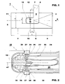
- the burner 1 is a part of a sequential combustion machine wherein a first portion of fuel is injected (in a first burner) in a main air flow to form a mixture; this mixture is combusted and is expanded in a high pressure turbine. Afterwards further fuel is injected (in a second burner) in the already expanded flow to form a mixture; also this mixture is combusted and expanded in a low pressure turbine.
- the burner 1 of the present invention is the second burner of the sequential combustion machine and has a tubular body 2 (which has a trapezoidal cross section with a high H) with an inlet 3 for the entrance of the gas flow A.
- the burner 1 Downstream of the inlet 3 the burner 1 has four vortex generators 4 of known type which extend along the longitudinal axis 5 of the burner 1.
- An upper and bottom vortex generators protrude from the upper and bottom walls of the trapezoidal body; these vortex generators are not shown in the figures.
- Two side vortex generators projects from the two side walls of the vortex generators and have trailing edges which lay in the same plane 6 perpendicular to the axis 5 of the burner 1.
- the burner 1 further comprises a lance 7 projecting into the body 2.
- the lance 7 has a fuel supply portion 8 which is outside the tubular body 2, an intermediate portion 9 which is inside the tubular body 2 and extends perpendicularly to the axis 5 of the burner 1, and a terminal portion 10 which is housed inside the tubular body 2 and extends from the intermediate part 9 of the lance.
- the terminal portion 10 extends in a direction opposite the inlet 3 and parallel to the longitudinal axis 5 of the burner 1.
- the terminal portion 10 is provided with four nozzle groups 12 for injecting a fuel into the tubular body 2.
- All of the nozzle groups 12 lay in an injection plane 15 which is perpendicular to the axis of the terminal portion 10 of the lance 7 (in the embodiment of figure 1 the axis of the terminal portion 10 of the lance 7 overlaps the axis 5, nevertheless in different embodiments the axis of the terminal portion of the lance does not overlap the axis 5 and is preferably parallel to it).
- the burner 1 Downstream of the lance 7, the burner 1 comprises an outlet 11 for supplying the mixture of gas (containing air) and fuel formed in the body 2 to the combustion chamber.
- the ratio x/L between the axial distance x between the side trailing edges of the vortex generators 4 and the injection plane 15 is equal to or less than 0.1052, preferably it is comprised between 0.000 and 0.1052.
- the ratio z/d is comprised between 0.17 and 1.35 and preferably between 0.420 and 0.854.
- the very particular configuration of the burner 1 allows the fuel to be injected in a zone where vortices with a very high swirl number exist.
- This configuration also allows a long mixing length to be obtained, without causing the fuel to be withheld in the burner for a too long time, in order to avoid flashback problems.
- the lance 7 comprises a first tubular element 20 arranged to carry a fuel and an outer tubular element 22 defining with said first tubular element 20 an annular conduit 24 arranged to carry air.
- the first tubular element 20 is provided with first nozzles 26 of said nozzle groups 12 and also the outer tubular element 22 is provided with outer nozzles 27 of the nozzle groups 12.
- each outer nozzle 27 is provided with a sleeve 28 protruding outwards.
- each sleeve 28 of the outer nozzles 27 is conical in shape and has a length from the external surface of the outer tubular element 22 to the free edge 29 which is equal or less than 10 millimetres and preferably it is comprised between 1-10 millimetres.
- the ratio between the outlet inner diameter and the inlet inner diameter of the sleeves 28 is greater than 50%, preferably comprised between 78 and 98% and more preferably between 85 and 91%.
- the conical sleeves contract the flow and keep it perpendicular to the main flow.
- This value of the length of the sleeves 28 let the penetration distance of the air/fuel injected be increased.
- each sleeve 28 of the outer nozzles 27 is rounded at the outer tubular element 22.
- the first tubular element 20 encloses a second tubular element 32 and defines with it an annular conduit 34; this second tubular element 32 has a closed end with second nozzles 36 of the nozzle groups 12.
- Such a structure allows the lance to eject a liquid fuel (through the tubular element 32) and/or a gaseous fuel (through the conduit 34) and also air (through the conduit 24).
- the second nozzles 36 are coaxial with the first nozzles 26, the outer nozzles 27 and the sleeves 28.
- first nozzles 26 and the second nozzles 36 of each group of nozzles 12 are provided with a cylindrical outwardly protruding portion 37, 38 having aligned free edges 39.
- the cylindrical portion 37 guides the gaseous fuel toward the exit and the cylindrical portion 38 guides the liquid fuel toward the exit.
- cylindrical portion 37 also has the function of guiding the carrier air toward the exit (the carrier air flows outside the cylindrical portion 37); in this respect the outer wall of the cylindrical portion 37 is conical in shape.
- cylindrical portions 37, 38 of the first and second nozzles 26, 36 are housed within the outer tubular element 22 and they are also outside the corresponding sleeves 28 of the outer tubular element 22 (in other words the free edges 39 are outside the sleeves 28 and inside the outer tubular element 22).
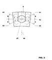
- the terminal portion 10 of the lance 7 has four nozzle groups 12 which are placed in the injection plane 15.
- the four nozzle groups have their axes 41, 42 which are differently angled with respect to a transversal plane 43.
- angles B of the nozzle groups 12 towards the intermediate portion 9 of the lance 7 are smaller than the corresponding angles C of the nozzle groups 12 opposite the intermediate portion 9 of the lance 7.
- angles B of the nozzle groups 12 towards the intermediate portion 9 of the lance 7 are smaller than 25° and greater than 15° and they are preferably about 20°.
- the nozzle groups 12 are symmetrically placed with respect to a longitudinal plane 45 which is perpendicular to the transversal plane 43.
- the gas flow coming from the high pressure turbine (which contains air) enters the burner from the inlet 3 and passes through the vortex generators; in this zone the turbulence of the gas flow increases and the vortices acquire a great swirl number.
- the fuel is injected along the injection plane 15, i.e. in a region of the burner which has a very precise distance from the side vortex generators trailing edges (this distance being defined by the ratio x/L); the ratio x/L allows the injection of fuel in a zone where the turbulence and the swirl number of the vortices are so high that optimization of the mixing of the fuel with the gas flow is obtained.
- angles B, C allow injection of the fuel also in a transversal zone where the turbulence and the swirl number of the vortices are very high and the presence of the sleeves at the outer nozzles allow penetration of the fuel jet into the gas flow.
- the fuel mixing performances have been measured in a water channel facility with a LIF system and the combustion performances including emissions have been assessed in a combustion rig at high pressure.
Landscapes
- Engineering & Computer Science (AREA)
- Chemical & Material Sciences (AREA)
- Combustion & Propulsion (AREA)
- Mechanical Engineering (AREA)
- General Engineering & Computer Science (AREA)
- Pre-Mixing And Non-Premixing Gas Burner (AREA)
- Gas Burners (AREA)
Claims (15)
- Brenner (1) einer Gasturbine, die Folgendes aufweist: einen rohrförmigen Körper (2) mit einem Einlass (3) für den Eintritt eines Gasstromes (A), stromabwärts vom Einlass (3) mindestens einen Seitenwirbelerzeuger (4) und eine Lanze (7), die in den rohrförmigen Körper (2) hineinragt und einen Endteil (10) aufweist, der sich parallel zur Längsachse (5) des Brenners (1) erstreckt, welcher mit vier Düsengruppen (12) versehen ist, um Brennstoff in den rohrförmigen Körper (2) einzuspritzen, wobei die vier Düsengruppen (12) in einer Einspritzebene (15) senkrecht zur Achse des Endteils (10) der Lanze (7) an einem stromabseitigen Teil der Lanze (7) liegen, wobei der Brenner (1) ferner einen Auslass (11) aufweist, wobei das Verhältnis x/L des axialen Abstands x zwischen einer Hinterkante des mindestens einen Seitenwirbelerzeugers (4) und der Einspritzebene (15) zur Länge L des rohrförmigen Körpers (2) gleich oder kleiner als 0,1052 ist, wobei:sich der Endteil (10) der Lanze (7) von einem Zwischenteil (9) aus erstreckt, der in das rohrförmige Element (2) eingesetzt ist und den Endteil (10) mit einem Brennstoffzuführungsteil (8) der Lanze (7) verbindet, der außerhalb des rohrförmigen Elements (2) liegt, wobei die vier Düsengruppen (12) ihre Achsen (41, 42) unter unterschiedlichen Winkeln bezüglich einer Transversalebene (43) ausgerichtet haben,wobei die Winkel (B), die von den zwei Achsen (41) der Düsengruppen (12), die zum Zwischenteil (9) der Lanze (7) hin liegen, und der Transversalebene (43) eingeschlossen werden, zueinander gleich sind,wobei die Winkel (C), die von den zwei Achsen (42) der Düsengruppen (12), die dem Zwischenteil (9) der Lanze (7) gegenüberliegen, und der Transversalebene (43) eingeschlossen werden, untereinander gleich sind,wobei die Winkel (B), die von den zwei Achsen (41) der Düsengruppen (12), die zum Zwischenteil (9) der Lanze (7) hin liegen, und der Transversalebene (43) eingeschlossen werden, kleiner als die Winkel (C) sind, die von den zwei Achsen (42) der Düsengruppen (12), die dem Zwischenteil (9) der Lanze (7) gegenüberliegen, und der Transversalebene (43) eingeschlossen werden.
- Brenner (1) nach Anspruch 1, dadurch gekennzeichnet, dass das Verhältnis x/L zwischen 0,000 und 0,1052 liegt.
- Brenner (1) nach Anspruch 1, dadurch gekennzeichnet, dass er zwei Seitenwirbelerzeuger aufweist, die Hinterkanten aufweisen, welche in einer Ebene (6) senkrecht zur Achse des Brenners (1) liegen.
- Brenner (1) nach Anspruch 1, dadurch gekennzeichnet, dass die Lanze (7) mindestens ein erstes rohrförmiges Element (20), das für den Transport eines Brennstoffs eingerichtet ist, und ein äußeres rohrförmiges Element (22) aufweist, das mit dem ersten rohrförmigen Element (20) einen ringförmigen Kanal (24) festlegt, der für die Luftzufuhr eingerichtet ist, wobei das erste rohrförmige Element (20) mit ersten Düsen (26) der Düsengruppen (12) versehen ist und wobei das äußere rohrförmige Element (22) mit äußeren Düsen (27) der Düsengruppen (12) versehen ist, wobei jede äußere Düse (27) mit einer Muffe (28) versehen ist, die nach außen ragt.
- Brenner (1) nach Anspruch 4, dadurch gekennzeichnet, dass die Länge einer jeden Muffe (28) der äußeren Düsen (27) von der Außenfläche des äußeren rohrförmigen Elements (22) zu ihrer freien Kante (29) gleich oder kleiner als 10 Millimeter ist und vorzugsweise zwischen 1-10 Millimeter liegt.
- Brenner (1) nach Anspruch 4, dadurch gekennzeichnet, dass die Innenfläche einer jeden Muffe (28) der äußeren Düsen (27) kegelförmig ist.
- Brenner (1) nach Anspruch 6, dadurch gekennzeichnet, dass das Verhältnis zwischen dem Auslassinnendurchmesser und dem Einlassinnendurchmesser der Muffe (28) größer als 50% ist, vorzugsweise zwischen 78-98% und insbesondere zwischen 85-91% liegt.
- Brenner (1) nach einem der Ansprüche 4 bis 7, dadurch gekennzeichnet, dass die Einlasskante (30) einer jeden Muffe (28) der äußeren Düsen (27) an dem äußeren rohrförmigen Element (22) abgerundet ist.
- Brenner (1) nach Anspruch 4, dadurch gekennzeichnet, dass das erste rohrförmige Element (20) ein zweites rohrförmiges Element (32) umschließt und mit ihm einen ringförmigen Kanal (34) festlegt, wobei das zweite rohrförmige Element (32) ein geschlossenes Ende mit zweiten Düsen (36) der zweiten Düsengruppen (12) aufweist, die koaxial mit den ersten Düsen (26) und den äußeren Düsen (27) und den Muffen (28) der äußeren Düsen sind.
- Brenner (1) nach Anspruch 9, dadurch gekennzeichnet, dass die ersten Düsen (26) und die zweiten Düsen (36) einer jeden Düsengruppe (12) mit zylindrisch nach außen vorstehenden Teilen (37, 38) versehen sind, die ausgerichtete freie Kanten (39) aufweisen.
- Brenner (1) nach Anspruch 10, dadurch gekennzeichnet, dass die Außenwand des zylindrischen Teils (37) der ersten Düsen (26) kegelförmig ist.
- Brenner (1) nach Anspruch 10, dadurch gekennzeichnet, dass die zylindrisch nach außen vorstehenden Teile (37, 38) der ersten und zweiten Düsen (26, 36) im äußeren rohrförmigen Element (22) und außerhalb der entsprechenden Muffen (28) des äußeren rohrförmigen Elements (22) untergebracht sind.
- Brenner (1) nach Anspruch 1, dadurch gekennzeichnet, dass die Winkel (B), die von den Achsen (41) der Düsengruppen (12), die zum Zwischenteil (9) der Lanze (7) hin liegen, und der Transversalebene (43) eingeschlossen werden, kleiner als 25° und größer als 15° und vorzugsweise circa 20° sind.
- Brenner (1) nach einem der vorhergehenden Ansprüche, dadurch gekennzeichnet, dass die Düsengruppen (12) symmetrisch bezüglich einer Longitudinalebene (45) angeordnet sind, die senkrecht zu der Transversalebene (43) ist.
- Brenner (1) nach einem der vorhergehenden Ansprüche, dadurch gekennzeichnet, dass er der zweite Brenner einer sequenziellen Verbrennungsmaschine ist.
Priority Applications (3)
| Application Number | Priority Date | Filing Date | Title |
|---|---|---|---|
| ES08172239T ES2400247T3 (es) | 2008-12-19 | 2008-12-19 | Quemador de una turbina de gas que tiene una configuración de lanza especial |
| EP20080172239 EP2199674B1 (de) | 2008-12-19 | 2008-12-19 | Brenner einer Gasturbine mit einer speziellen Lanzenkonfiguration |
| US12/642,086 US8938968B2 (en) | 2008-12-19 | 2009-12-18 | Burner of a gas turbine |
Applications Claiming Priority (1)
| Application Number | Priority Date | Filing Date | Title |
|---|---|---|---|
| EP20080172239 EP2199674B1 (de) | 2008-12-19 | 2008-12-19 | Brenner einer Gasturbine mit einer speziellen Lanzenkonfiguration |
Publications (2)
| Publication Number | Publication Date |
|---|---|
| EP2199674A1 EP2199674A1 (de) | 2010-06-23 |
| EP2199674B1 true EP2199674B1 (de) | 2012-11-21 |
Family
ID=40690258
Family Applications (1)
| Application Number | Title | Priority Date | Filing Date |
|---|---|---|---|
| EP20080172239 Active EP2199674B1 (de) | 2008-12-19 | 2008-12-19 | Brenner einer Gasturbine mit einer speziellen Lanzenkonfiguration |
Country Status (3)
| Country | Link |
|---|---|
| US (1) | US8938968B2 (de) |
| EP (1) | EP2199674B1 (de) |
| ES (1) | ES2400247T3 (de) |
Families Citing this family (15)
| Publication number | Priority date | Publication date | Assignee | Title |
|---|---|---|---|---|
| EP2388520B1 (de) * | 2010-05-20 | 2016-10-26 | General Electric Technology GmbH | Lanze eines Gasturbinenbrenners |
| EP2420730B1 (de) | 2010-08-16 | 2018-03-07 | Ansaldo Energia IP UK Limited | Nachbrenner |
| US20130152555A1 (en) * | 2011-12-15 | 2013-06-20 | Caterpillar Inc. | Fluid injection lance with balanced flow distribution |
| CN104204680B (zh) * | 2012-03-23 | 2016-01-06 | 阿尔斯通技术有限公司 | 燃烧装置 |
| EP2685170A1 (de) | 2012-07-10 | 2014-01-15 | Alstom Technology Ltd | Gekühlte Wandstruktur für die Heißgasteile einer Gasturbine und Verfahren zur Herstellung solch einer Struktur |
| EP2789915A1 (de) * | 2013-04-10 | 2014-10-15 | Alstom Technology Ltd | Verfahren zum Betrieb einer Brennkammer und Brennkammer |
| WO2014179956A1 (en) * | 2013-05-09 | 2014-11-13 | Zheng Shi | System and method for small-scale combustion of pulverized solid fuels |
| US10094570B2 (en) | 2014-12-11 | 2018-10-09 | General Electric Company | Injector apparatus and reheat combustor |
| US10107498B2 (en) | 2014-12-11 | 2018-10-23 | General Electric Company | Injection systems for fuel and gas |
| US10094569B2 (en) | 2014-12-11 | 2018-10-09 | General Electric Company | Injecting apparatus with reheat combustor and turbomachine |
| US10094571B2 (en) | 2014-12-11 | 2018-10-09 | General Electric Company | Injector apparatus with reheat combustor and turbomachine |
| CN106642127A (zh) * | 2016-11-24 | 2017-05-10 | 兴化市紫邦燃器具科技有限公司 | 强制全预混三维混气室 |
| GB201700459D0 (en) * | 2017-01-11 | 2017-02-22 | Rolls Royce Plc | Fuel injector |
| GB201700465D0 (en) * | 2017-01-11 | 2017-02-22 | Rolls Royce Plc | Fuel injector |
| EP3657072B1 (de) * | 2018-11-23 | 2021-08-11 | Ansaldo Energia Switzerland AG | Lanze für einen brenner und verfahren zum nachrüsten einer lanze |
Family Cites Families (12)
| Publication number | Priority date | Publication date | Assignee | Title |
|---|---|---|---|---|
| DE3261484D1 (en) * | 1981-03-04 | 1985-01-24 | Bbc Brown Boveri & Cie | Annular combustion chamber with an annular burner for gas turbines |
| US5293843A (en) * | 1992-12-09 | 1994-03-15 | A. Ahlstrom Corporation | Combustor or gasifier for application in pressurized systems |
| EP0623786B1 (de) | 1993-04-08 | 1997-05-21 | Asea Brown Boveri Ag | Brennkammer |
| DE4326802A1 (de) * | 1993-08-10 | 1995-02-16 | Abb Management Ag | Brennstofflanze für flüssige und/oder gasförmige Brennstoffe sowie Verfahren zu deren Betrieb |
| DE4446611A1 (de) * | 1994-12-24 | 1996-06-27 | Abb Management Ag | Brennkammer |
| DE19510744A1 (de) | 1995-03-24 | 1996-09-26 | Abb Management Ag | Brennkammer mit Zweistufenverbrennung |
| GB2307980B (en) * | 1995-12-06 | 2000-07-05 | Europ Gas Turbines Ltd | A fuel injector arrangement; a method of operating a fuel injector arrangement |
| US6325818B1 (en) * | 1999-10-07 | 2001-12-04 | Innercool Therapies, Inc. | Inflatable cooling apparatus for selective organ hypothermia |
| DE19905996A1 (de) | 1999-02-15 | 2000-08-17 | Abb Alstom Power Ch Ag | Brennstofflanze zum Eindüsen von flüssigen und/oder gasförmigen Brennstoffen in eine Brennkammer |
| DE102004041272B4 (de) * | 2004-08-23 | 2017-07-13 | General Electric Technology Gmbh | Hybridbrennerlanze |
| WO2009019114A2 (de) * | 2007-08-07 | 2009-02-12 | Alstom Technology Ltd | Brenner für eine brennkammer einer turbogruppe |
| EP2179222B2 (de) * | 2007-08-07 | 2021-12-01 | Ansaldo Energia IP UK Limited | Brenner für eine brennkammer einer turbogruppe |
-
2008
- 2008-12-19 ES ES08172239T patent/ES2400247T3/es active Active
- 2008-12-19 EP EP20080172239 patent/EP2199674B1/de active Active
-
2009
- 2009-12-18 US US12/642,086 patent/US8938968B2/en active Active
Also Published As
| Publication number | Publication date |
|---|---|
| EP2199674A1 (de) | 2010-06-23 |
| ES2400247T3 (es) | 2013-04-08 |
| US20100236246A1 (en) | 2010-09-23 |
| US8938968B2 (en) | 2015-01-27 |
Similar Documents
| Publication | Publication Date | Title |
|---|---|---|
| EP2199674B1 (de) | Brenner einer Gasturbine mit einer speziellen Lanzenkonfiguration | |
| CN106164592B (zh) | 燃烧器、具有这种燃烧器的燃气轮机和燃料喷嘴 | |
| EP2400216B1 (de) | Lanze für einen Reheat Brenner | |
| RU2450211C2 (ru) | Трубчатая камера сгорания с ударным охлаждением | |
| US7565794B2 (en) | Premix burner for a gas turbine combustion chamber | |
| EP2496880A2 (de) | Injektionssystem für einen nachbrenner | |
| WO2011054757A2 (en) | Reheat burner injection system with fuel lances | |
| CN102165258A (zh) | 燃料喷嘴 | |
| EP2211109A1 (de) | Brenner einer Gasturbine und Verfahren zum Mischen eines Kraftstoffs mit einem gasförmigen Strom | |
| US20120227407A1 (en) | Burner for a turbine | |
| CN107525096B (zh) | 多管延迟贫喷射器 | |
| CN102759122A (zh) | 燃料喷嘴和用于运行燃烧器的方法 | |
| US9441837B2 (en) | Premix burner of the multi-cone type for a gas turbine | |
| KR101546216B1 (ko) | 가스 터빈용 다중 원추형 예혼합 버너 | |
| US5505615A (en) | Device for mixing a gaseous fuel with air and combustor provided with such a device | |
| EP2253888B1 (de) | Gasturbinenbrenner mit einem Wirbelerzeuger mit Brennstofflanze | |
| EP2420730B1 (de) | Nachbrenner | |
| JP6134510B2 (ja) | ターボ機械の燃焼器 | |
| RO131144B1 (ro) | Cameră de ardere cu preamestec şi turbionare |
Legal Events
| Date | Code | Title | Description |
|---|---|---|---|
| PUAI | Public reference made under article 153(3) epc to a published international application that has entered the european phase |
Free format text: ORIGINAL CODE: 0009012 |
|
| AK | Designated contracting states |
Kind code of ref document: A1 Designated state(s): AT BE BG CH CY CZ DE DK EE ES FI FR GB GR HR HU IE IS IT LI LT LU LV MC MT NL NO PL PT RO SE SI SK TR |
|
| AX | Request for extension of the european patent |
Extension state: AL BA MK RS |
|
| 17P | Request for examination filed |
Effective date: 20101213 |
|
| AKX | Designation fees paid |
Designated state(s): AT BE BG CH CY CZ DE DK EE ES FI FR GB GR HR HU IE IS IT LI LT LU LV MC MT NL NO PL PT RO SE SI SK TR |
|
| GRAP | Despatch of communication of intention to grant a patent |
Free format text: ORIGINAL CODE: EPIDOSNIGR1 |
|
| GRAS | Grant fee paid |
Free format text: ORIGINAL CODE: EPIDOSNIGR3 |
|
| GRAA | (expected) grant |
Free format text: ORIGINAL CODE: 0009210 |
|
| AK | Designated contracting states |
Kind code of ref document: B1 Designated state(s): AT BE BG CH CY CZ DE DK EE ES FI FR GB GR HR HU IE IS IT LI LT LU LV MC MT NL NO PL PT RO SE SI SK TR |
|
| REG | Reference to a national code |
Ref country code: GB Ref legal event code: FG4D |
|
| REG | Reference to a national code |
Ref country code: CH Ref legal event code: EP |
|
| REG | Reference to a national code |
Ref country code: AT Ref legal event code: REF Ref document number: 585285 Country of ref document: AT Kind code of ref document: T Effective date: 20121215 |
|
| REG | Reference to a national code |
Ref country code: IE Ref legal event code: FG4D |
|
| REG | Reference to a national code |
Ref country code: DE Ref legal event code: R096 Ref document number: 602008020219 Country of ref document: DE Effective date: 20130117 |
|
| REG | Reference to a national code |
Ref country code: NL Ref legal event code: T3 |
|
| REG | Reference to a national code |
Ref country code: ES Ref legal event code: FG2A Ref document number: 2400247 Country of ref document: ES Kind code of ref document: T3 Effective date: 20130408 |
|
| REG | Reference to a national code |
Ref country code: AT Ref legal event code: MK05 Ref document number: 585285 Country of ref document: AT Kind code of ref document: T Effective date: 20121121 |
|
| REG | Reference to a national code |
Ref country code: LT Ref legal event code: MG4D |
|
| PG25 | Lapsed in a contracting state [announced via postgrant information from national office to epo] |
Ref country code: LT Free format text: LAPSE BECAUSE OF FAILURE TO SUBMIT A TRANSLATION OF THE DESCRIPTION OR TO PAY THE FEE WITHIN THE PRESCRIBED TIME-LIMIT Effective date: 20121121 Ref country code: NO Free format text: LAPSE BECAUSE OF FAILURE TO SUBMIT A TRANSLATION OF THE DESCRIPTION OR TO PAY THE FEE WITHIN THE PRESCRIBED TIME-LIMIT Effective date: 20130221 Ref country code: FI Free format text: LAPSE BECAUSE OF FAILURE TO SUBMIT A TRANSLATION OF THE DESCRIPTION OR TO PAY THE FEE WITHIN THE PRESCRIBED TIME-LIMIT Effective date: 20121121 Ref country code: SE Free format text: LAPSE BECAUSE OF FAILURE TO SUBMIT A TRANSLATION OF THE DESCRIPTION OR TO PAY THE FEE WITHIN THE PRESCRIBED TIME-LIMIT Effective date: 20121121 |
|
| PG25 | Lapsed in a contracting state [announced via postgrant information from national office to epo] |
Ref country code: LV Free format text: LAPSE BECAUSE OF FAILURE TO SUBMIT A TRANSLATION OF THE DESCRIPTION OR TO PAY THE FEE WITHIN THE PRESCRIBED TIME-LIMIT Effective date: 20121121 Ref country code: SI Free format text: LAPSE BECAUSE OF FAILURE TO SUBMIT A TRANSLATION OF THE DESCRIPTION OR TO PAY THE FEE WITHIN THE PRESCRIBED TIME-LIMIT Effective date: 20121121 Ref country code: BE Free format text: LAPSE BECAUSE OF FAILURE TO SUBMIT A TRANSLATION OF THE DESCRIPTION OR TO PAY THE FEE WITHIN THE PRESCRIBED TIME-LIMIT Effective date: 20121121 Ref country code: GR Free format text: LAPSE BECAUSE OF FAILURE TO SUBMIT A TRANSLATION OF THE DESCRIPTION OR TO PAY THE FEE WITHIN THE PRESCRIBED TIME-LIMIT Effective date: 20130222 Ref country code: PL Free format text: LAPSE BECAUSE OF FAILURE TO SUBMIT A TRANSLATION OF THE DESCRIPTION OR TO PAY THE FEE WITHIN THE PRESCRIBED TIME-LIMIT Effective date: 20121121 Ref country code: PT Free format text: LAPSE BECAUSE OF FAILURE TO SUBMIT A TRANSLATION OF THE DESCRIPTION OR TO PAY THE FEE WITHIN THE PRESCRIBED TIME-LIMIT Effective date: 20130321 |
|
| PG25 | Lapsed in a contracting state [announced via postgrant information from national office to epo] |
Ref country code: AT Free format text: LAPSE BECAUSE OF FAILURE TO SUBMIT A TRANSLATION OF THE DESCRIPTION OR TO PAY THE FEE WITHIN THE PRESCRIBED TIME-LIMIT Effective date: 20121121 |
|
| PG25 | Lapsed in a contracting state [announced via postgrant information from national office to epo] |
Ref country code: DK Free format text: LAPSE BECAUSE OF FAILURE TO SUBMIT A TRANSLATION OF THE DESCRIPTION OR TO PAY THE FEE WITHIN THE PRESCRIBED TIME-LIMIT Effective date: 20121121 Ref country code: EE Free format text: LAPSE BECAUSE OF FAILURE TO SUBMIT A TRANSLATION OF THE DESCRIPTION OR TO PAY THE FEE WITHIN THE PRESCRIBED TIME-LIMIT Effective date: 20121121 Ref country code: CZ Free format text: LAPSE BECAUSE OF FAILURE TO SUBMIT A TRANSLATION OF THE DESCRIPTION OR TO PAY THE FEE WITHIN THE PRESCRIBED TIME-LIMIT Effective date: 20121121 Ref country code: SK Free format text: LAPSE BECAUSE OF FAILURE TO SUBMIT A TRANSLATION OF THE DESCRIPTION OR TO PAY THE FEE WITHIN THE PRESCRIBED TIME-LIMIT Effective date: 20121121 Ref country code: BG Free format text: LAPSE BECAUSE OF FAILURE TO SUBMIT A TRANSLATION OF THE DESCRIPTION OR TO PAY THE FEE WITHIN THE PRESCRIBED TIME-LIMIT Effective date: 20130221 Ref country code: MC Free format text: LAPSE BECAUSE OF NON-PAYMENT OF DUE FEES Effective date: 20121231 |
|
| REG | Reference to a national code |
Ref country code: CH Ref legal event code: PL |
|
| PG25 | Lapsed in a contracting state [announced via postgrant information from national office to epo] |
Ref country code: RO Free format text: LAPSE BECAUSE OF FAILURE TO SUBMIT A TRANSLATION OF THE DESCRIPTION OR TO PAY THE FEE WITHIN THE PRESCRIBED TIME-LIMIT Effective date: 20121121 |
|
| PLBE | No opposition filed within time limit |
Free format text: ORIGINAL CODE: 0009261 |
|
| STAA | Information on the status of an ep patent application or granted ep patent |
Free format text: STATUS: NO OPPOSITION FILED WITHIN TIME LIMIT |
|
| 26N | No opposition filed |
Effective date: 20130822 |
|
| PG25 | Lapsed in a contracting state [announced via postgrant information from national office to epo] |
Ref country code: LI Free format text: LAPSE BECAUSE OF NON-PAYMENT OF DUE FEES Effective date: 20121231 Ref country code: CH Free format text: LAPSE BECAUSE OF NON-PAYMENT OF DUE FEES Effective date: 20121231 |
|
| PG25 | Lapsed in a contracting state [announced via postgrant information from national office to epo] |
Ref country code: MT Free format text: LAPSE BECAUSE OF FAILURE TO SUBMIT A TRANSLATION OF THE DESCRIPTION OR TO PAY THE FEE WITHIN THE PRESCRIBED TIME-LIMIT Effective date: 20121121 |
|
| REG | Reference to a national code |
Ref country code: DE Ref legal event code: R097 Ref document number: 602008020219 Country of ref document: DE Effective date: 20130822 |
|
| PG25 | Lapsed in a contracting state [announced via postgrant information from national office to epo] |
Ref country code: HR Free format text: LAPSE BECAUSE OF FAILURE TO SUBMIT A TRANSLATION OF THE DESCRIPTION OR TO PAY THE FEE WITHIN THE PRESCRIBED TIME-LIMIT Effective date: 20130731 |
|
| PG25 | Lapsed in a contracting state [announced via postgrant information from national office to epo] |
Ref country code: TR Free format text: LAPSE BECAUSE OF FAILURE TO SUBMIT A TRANSLATION OF THE DESCRIPTION OR TO PAY THE FEE WITHIN THE PRESCRIBED TIME-LIMIT Effective date: 20121121 |
|
| PG25 | Lapsed in a contracting state [announced via postgrant information from national office to epo] |
Ref country code: LU Free format text: LAPSE BECAUSE OF NON-PAYMENT OF DUE FEES Effective date: 20121219 Ref country code: CY Free format text: LAPSE BECAUSE OF FAILURE TO SUBMIT A TRANSLATION OF THE DESCRIPTION OR TO PAY THE FEE WITHIN THE PRESCRIBED TIME-LIMIT Effective date: 20121121 |
|
| PG25 | Lapsed in a contracting state [announced via postgrant information from national office to epo] |
Ref country code: HU Free format text: LAPSE BECAUSE OF FAILURE TO SUBMIT A TRANSLATION OF THE DESCRIPTION OR TO PAY THE FEE WITHIN THE PRESCRIBED TIME-LIMIT Effective date: 20081219 |
|
| REG | Reference to a national code |
Ref country code: FR Ref legal event code: PLFP Year of fee payment: 8 |
|
| PG25 | Lapsed in a contracting state [announced via postgrant information from national office to epo] |
Ref country code: IS Free format text: LAPSE BECAUSE OF FAILURE TO SUBMIT A TRANSLATION OF THE DESCRIPTION OR TO PAY THE FEE WITHIN THE PRESCRIBED TIME-LIMIT Effective date: 20121121 |
|
| REG | Reference to a national code |
Ref country code: DE Ref legal event code: R081 Ref document number: 602008020219 Country of ref document: DE Owner name: GENERAL ELECTRIC TECHNOLOGY GMBH, CH Free format text: FORMER OWNER: ALSTOM TECHNOLOGY LTD., BADEN, CH Ref country code: DE Ref legal event code: R081 Ref document number: 602008020219 Country of ref document: DE Owner name: ANSALDO ENERGIA IP UK LIMITED, GB Free format text: FORMER OWNER: ALSTOM TECHNOLOGY LTD., BADEN, CH |
|
| REG | Reference to a national code |
Ref country code: ES Ref legal event code: PC2A Owner name: GENERAL ELECTRIC TECHNOLOGY GMBH Effective date: 20161021 |
|
| REG | Reference to a national code |
Ref country code: NL Ref legal event code: HC Owner name: GENERAL ELECTRIC TECHNOLOGY GMBH; CH Free format text: DETAILS ASSIGNMENT: VERANDERING VAN EIGENAAR(S), VERANDERING VAN NAAM VAN DE EIGENAAR(S); FORMER OWNER NAME: ALSTOM TECHNOLOGY LTD Effective date: 20161006 |
|
| REG | Reference to a national code |
Ref country code: FR Ref legal event code: CD Owner name: ALSTOM TECHNOLOGY LTD, CH Effective date: 20161110 |
|
| REG | Reference to a national code |
Ref country code: FR Ref legal event code: PLFP Year of fee payment: 9 |
|
| PGFP | Annual fee paid to national office [announced via postgrant information from national office to epo] |
Ref country code: IE Payment date: 20161227 Year of fee payment: 9 Ref country code: GB Payment date: 20161222 Year of fee payment: 9 Ref country code: NL Payment date: 20161221 Year of fee payment: 9 |
|
| REG | Reference to a national code |
Ref country code: NL Ref legal event code: PD Owner name: ANSALDO ENERGIA IP UK LIMITED; GB Free format text: DETAILS ASSIGNMENT: CHANGE OF OWNER(S), ASSIGNMENT; FORMER OWNER NAME: GENERAL ELECTRIC TECHNOLOGY GMBH Effective date: 20170301 |
|
| REG | Reference to a national code |
Ref country code: DE Ref legal event code: R081 Ref document number: 602008020219 Country of ref document: DE Owner name: ANSALDO ENERGIA IP UK LIMITED, GB Free format text: FORMER OWNER: GENERAL ELECTRIC TECHNOLOGY GMBH, BADEN, CH |
|
| REG | Reference to a national code |
Ref country code: GB Ref legal event code: 732E Free format text: REGISTERED BETWEEN 20170824 AND 20170830 |
|
| REG | Reference to a national code |
Ref country code: ES Ref legal event code: PC2A Owner name: ANSALDO ENERGIA IP UK LIMITED Effective date: 20170927 |
|
| REG | Reference to a national code |
Ref country code: FR Ref legal event code: PLFP Year of fee payment: 10 |
|
| REG | Reference to a national code |
Ref country code: FR Ref legal event code: TP Owner name: ANSALDO ENERGIA IP UK LIMITED, GB Effective date: 20171221 |
|
| PGFP | Annual fee paid to national office [announced via postgrant information from national office to epo] |
Ref country code: FR Payment date: 20171221 Year of fee payment: 10 |
|
| PGFP | Annual fee paid to national office [announced via postgrant information from national office to epo] |
Ref country code: ES Payment date: 20180124 Year of fee payment: 10 |
|
| REG | Reference to a national code |
Ref country code: NL Ref legal event code: MM Effective date: 20180101 |
|
| GBPC | Gb: european patent ceased through non-payment of renewal fee |
Effective date: 20171219 |
|
| REG | Reference to a national code |
Ref country code: IE Ref legal event code: MM4A |
|
| PG25 | Lapsed in a contracting state [announced via postgrant information from national office to epo] |
Ref country code: NL Free format text: LAPSE BECAUSE OF NON-PAYMENT OF DUE FEES Effective date: 20180101 |
|
| PG25 | Lapsed in a contracting state [announced via postgrant information from national office to epo] |
Ref country code: IE Free format text: LAPSE BECAUSE OF NON-PAYMENT OF DUE FEES Effective date: 20171219 |
|
| PG25 | Lapsed in a contracting state [announced via postgrant information from national office to epo] |
Ref country code: GB Free format text: LAPSE BECAUSE OF NON-PAYMENT OF DUE FEES Effective date: 20171219 |
|
| PG25 | Lapsed in a contracting state [announced via postgrant information from national office to epo] |
Ref country code: FR Free format text: LAPSE BECAUSE OF NON-PAYMENT OF DUE FEES Effective date: 20181231 |
|
| REG | Reference to a national code |
Ref country code: ES Ref legal event code: FD2A Effective date: 20200204 |
|
| PG25 | Lapsed in a contracting state [announced via postgrant information from national office to epo] |
Ref country code: ES Free format text: LAPSE BECAUSE OF NON-PAYMENT OF DUE FEES Effective date: 20181220 |
|
| P01 | Opt-out of the competence of the unified patent court (upc) registered |
Effective date: 20240430 |
|
| PGFP | Annual fee paid to national office [announced via postgrant information from national office to epo] |
Ref country code: DE Payment date: 20251222 Year of fee payment: 18 |
|
| PGFP | Annual fee paid to national office [announced via postgrant information from national office to epo] |
Ref country code: IT Payment date: 20251231 Year of fee payment: 18 |