EP2199744A2 - Sensorvorrichtung - Google Patents
Sensorvorrichtung Download PDFInfo
- Publication number
- EP2199744A2 EP2199744A2 EP09178581A EP09178581A EP2199744A2 EP 2199744 A2 EP2199744 A2 EP 2199744A2 EP 09178581 A EP09178581 A EP 09178581A EP 09178581 A EP09178581 A EP 09178581A EP 2199744 A2 EP2199744 A2 EP 2199744A2
- Authority
- EP
- European Patent Office
- Prior art keywords
- angular velocity
- sensing signal
- signal
- acceleration
- sensor
- Prior art date
- Legal status (The legal status is an assumption and is not a legal conclusion. Google has not performed a legal analysis and makes no representation as to the accuracy of the status listed.)
- Ceased
Links
- 230000001133 acceleration Effects 0.000 claims description 54
- 238000001514 detection method Methods 0.000 claims description 17
- 230000008054 signal transmission Effects 0.000 description 7
- 238000010586 diagram Methods 0.000 description 3
- 239000000284 extract Substances 0.000 description 2
- 238000000034 method Methods 0.000 description 2
- 238000005259 measurement Methods 0.000 description 1
Images

Classifications
-
- G—PHYSICS
- G01—MEASURING; TESTING
- G01P—MEASURING LINEAR OR ANGULAR SPEED, ACCELERATION, DECELERATION, OR SHOCK; INDICATING PRESENCE, ABSENCE, OR DIRECTION, OF MOVEMENT
- G01P15/00—Measuring acceleration; Measuring deceleration; Measuring shock, i.e. sudden change of acceleration
- G01P15/02—Measuring acceleration; Measuring deceleration; Measuring shock, i.e. sudden change of acceleration by making use of inertia forces using solid seismic masses
-
- G—PHYSICS
- G01—MEASURING; TESTING
- G01C—MEASURING DISTANCES, LEVELS OR BEARINGS; SURVEYING; NAVIGATION; GYROSCOPIC INSTRUMENTS; PHOTOGRAMMETRY OR VIDEOGRAMMETRY
- G01C21/00—Navigation; Navigational instruments not provided for in groups G01C1/00 - G01C19/00
- G01C21/10—Navigation; Navigational instruments not provided for in groups G01C1/00 - G01C19/00 by using measurements of speed or acceleration
- G01C21/12—Navigation; Navigational instruments not provided for in groups G01C1/00 - G01C19/00 by using measurements of speed or acceleration executed aboard the object being navigated; Dead reckoning
- G01C21/16—Navigation; Navigational instruments not provided for in groups G01C1/00 - G01C19/00 by using measurements of speed or acceleration executed aboard the object being navigated; Dead reckoning by integrating acceleration or speed, i.e. inertial navigation
-
- G—PHYSICS
- G01—MEASURING; TESTING
- G01P—MEASURING LINEAR OR ANGULAR SPEED, ACCELERATION, DECELERATION, OR SHOCK; INDICATING PRESENCE, ABSENCE, OR DIRECTION, OF MOVEMENT
- G01P3/00—Measuring linear or angular speed; Measuring differences of linear or angular speeds
Definitions
- the present invention relates to sensor devices used in electronic devices and vehicles, including digital cameras and automobile navigation systems.
- a conventional sensor device includes angular velocity sensor 1 for outputting an angular velocity sensing signal, and acceleration sensor 2 for outputting an acceleration sensing signal.
- a prior art related to the present invention is disclosed, for example, in Japanese Patent Unexamined Publication No. 2005-283481 .
- the conventional sensor device has a disadvantage of its low detection accuracy.
- the sensor device uses gravitational acceleration information from acceleration sensor 2 for correcting angular velocity information from angular velocity sensor 1. This enables detection of a spiral travel of the vehicle in the multistory parking lot.
- an output on gravitational acceleration from acceleration sensor 2 and an output on angular velocity sensor 1 are not linked timewise. Accordingly, if there is a difference in signal transmission time between a circuit of angular velocity sensor 1 and a circuit of acceleration sensor 2, the angular velocity information cannot be accurately corrected using the gravitational acceleration information from acceleration sensor 2. This results in low detection accuracy.
- An object of the present invention is to improve the detection accuracy of sensor device.
- the present invention includes an output circuit for outputting an angular velocity sensing signal and an acceleration sensing signal detected at the same timing in a digital format according to the time-division system, so as to link these signals timewise.
- This structure enables output of the angular velocity sensing signal and the acceleration sensing signal linked timewise as one signal. Accordingly, the angular velocity sensing signal can be accurately corrected using the acceleration sensing signal. As a result, the detection accuracy of sensor device improves.
- Fig 1 is an electrical circuit diagram of the sensor device in the first exemplary embodiment of the present invention.
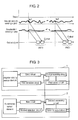
- Fig. 2 illustrates changes in an output signal of the sensor device in the first exemplary embodiment.
- the sensor device includes angular velocity sensor 9 for outputting an angular velocity sensing signal, acceleration sensor 10 for outputting an acceleration sensing signal, and output circuit 19 for outputting the angular velocity sensing signal and the acceleration sensing signal.
- Angular velocity sensor 9 includes drive circuit 11 for outputting a drive signal that drives an angular velocity sensor element, and angular velocity sensor element 12 that receives the drive signal from drive circuit 11.
- Angular velocity sensor 9 also includes detection circuit 13 for taking out a response signal from angular velocity sensor element 12, and first processing circuit 14 that receives a response signal from first detection circuit 13.
- First processing circuit 14 extracts and outputs the angular velocity sensing signal from the response signal.
- Acceleration sensor 10 includes bias circuit 15 for outputting a bias signal, and acceleration sensor element 16 that receives the bias signal. Acceleration sensor 10 also includes second detection circuit 17 for taking out a response signal from acceleration sensor element 16, and second processing circuit 18 that receives a response signal from second detection circuit 17. Second processing circuit 18 extracts and outputs the acceleration sensing signal from the response signal.
- output circuit 19 outputs in a digital format according to the time-division system the angular velocity sensing signal and the acceleration sensing signal detected at ts1 point, i.e., the angular velocity sensing signal and the acceleration sensing signal detected at the same timing, so as to link these signals timewise.
- an A/D converter is provided in output circuit 19, instead of providing it in first and second detection circuits 13 and 17 or first and second processing circuits 14 and 18, a chopper needs to be provided before the A/D converter so as to separate to analog angular velocity signal and analog acceleration signal for output.
- the chopper is not necessarily provided before the A/D converter (not illustrated).
- the angular velocity sensing signal and the acceleration sensing signal can be linked timewise as one signal. This enables accurate correction of the angular velocity sensing signal using the acceleration sensing signal. Accordingly, the detection accuracy of the sensor device can be improved.
- the sensor device corrects the angular velocity sensing signal from angular velocity sensor 9, using gravitational acceleration information included in the acceleration sensing signal from acceleration sensor 10, and detects a spiral travel of the vehicle in the multistory parking lot.
- the sensor device in this exemplary embodiment can accurately correct the angular velocity information based on the gravitational acceleration information from acceleration sensor 10, even if there is a time difference in signal transmission between a circuit of angular velocity sensor 9 and a circuit of acceleration sensor 10. This is because the acceleration sensing signal including the gravitational acceleration information from acceleration sensor 10 and the angular velocity sensing signal from angular velocity sensor 9 are linked timewise. As a result, the detection accuracy of the sensor device can be improved.
- a time difference in signal transmission between the circuit of angular velocity sensor 9 and the circuit of acceleration sensor 10 is calculated. If the signal transmission time in the circuit of angular velocity sensor 9 is shorter than the signal transmission time in the circuit of acceleration sensor 10, a delay circuit is provided in angular velocity sensor 9. Contrarily, if the signal transmission time in the circuit of acceleration sensor 10 is shorter than the signal transmission time in the circuit of angular velocity sensor 9, a delay circuit is provided in acceleration sensor 10.
- the angular velocity sensing signal and the acceleration sensing signal detected at the same timing are input to output circuit 19 at the same timing.
- the angular velocity sensing signal and the acceleration sensing signal detected at the same timing can thus be linked timewise and output as one signal when output circuit 19 sequentially outputs the angular velocity sensing signal and the acceleration sensing signal.
- Another method is to provide a time-point information measurement unit for calculating time-point information, and adding this time-point information to the angular velocity sensing signal and the acceleration sensing signal. Then, output circuit 19 links the angular velocity sensing signal and the acceleration sensing signal having the same time-point information, and outputs these signals as one signal.
Landscapes
- Engineering & Computer Science (AREA)
- Radar, Positioning & Navigation (AREA)
- Remote Sensing (AREA)
- Physics & Mathematics (AREA)
- General Physics & Mathematics (AREA)
- Automation & Control Theory (AREA)
- Gyroscopes (AREA)
- Navigation (AREA)
Applications Claiming Priority (1)
| Application Number | Priority Date | Filing Date | Title |
|---|---|---|---|
| JP2008323685A JP2010145274A (ja) | 2008-12-19 | 2008-12-19 | 慣性センサ |
Publications (2)
| Publication Number | Publication Date |
|---|---|
| EP2199744A2 true EP2199744A2 (de) | 2010-06-23 |
| EP2199744A3 EP2199744A3 (de) | 2011-04-06 |
Family
ID=41566433
Family Applications (1)
| Application Number | Title | Priority Date | Filing Date |
|---|---|---|---|
| EP09178581A Ceased EP2199744A3 (de) | 2008-12-19 | 2009-12-10 | Sensorvorrichtung |
Country Status (5)
| Country | Link |
|---|---|
| US (1) | US8276448B2 (de) |
| EP (1) | EP2199744A3 (de) |
| JP (1) | JP2010145274A (de) |
| KR (1) | KR20100071927A (de) |
| CN (1) | CN101750510A (de) |
Families Citing this family (7)
| Publication number | Priority date | Publication date | Assignee | Title |
|---|---|---|---|---|
| US9008757B2 (en) | 2012-09-26 | 2015-04-14 | Stryker Corporation | Navigation system including optical and non-optical sensors |
| JP2014149218A (ja) * | 2013-02-01 | 2014-08-21 | Hitachi Automotive Systems Ltd | 慣性力検出装置 |
| WO2015039330A1 (en) * | 2013-09-22 | 2015-03-26 | Telefonaktiebolaget L M Ericsson (Publ) | Pll and adaptive compensation method in pll |
| TWI650558B (zh) * | 2015-05-20 | 2019-02-11 | 美商路梅戴尼科技公司 | 用於決定慣性參數之方法及系統 |
| US10316884B2 (en) | 2015-06-18 | 2019-06-11 | Matthew C. Prestwich | Motion activated switch and method |
| DE102017221868A1 (de) * | 2017-12-05 | 2019-06-06 | BSH Hausgeräte GmbH | Haushaltsgerät mit Sensor zum Detektieren einer Türbewegung |
| CN112611883A (zh) * | 2020-12-04 | 2021-04-06 | 北京融智世纪节能技术服务有限公司 | 一种转速信号同步测量方法 |
Citations (1)
| Publication number | Priority date | Publication date | Assignee | Title |
|---|---|---|---|---|
| US20040064252A1 (en) | 2002-09-26 | 2004-04-01 | Honeywell International Inc. | Method and system for processing pulse signals within an inertial navigation system |
Family Cites Families (20)
| Publication number | Priority date | Publication date | Assignee | Title |
|---|---|---|---|---|
| JPH0672899B2 (ja) * | 1988-04-01 | 1994-09-14 | 株式会社日立製作所 | 加速度センサ |
| JPH07239236A (ja) | 1994-02-28 | 1995-09-12 | Hitachi Ltd | 移動体の状態量計測方法と装置および移動体の姿勢角演算装置 |
| US5935191A (en) * | 1994-11-08 | 1999-08-10 | Matsushita Electric Industrial Co., Ltd. | Navigation apparatus for a vehicle |
| WO1996038712A1 (fr) * | 1995-05-30 | 1996-12-05 | Matsushita Electric Industrial Co., Ltd. | Capteur de vitesse angulaire |
| JP3272960B2 (ja) | 1996-08-19 | 2002-04-08 | 株式会社データ・テック | ドライビングレコーダ及び車両の運行解析装置 |
| DE19827688A1 (de) * | 1997-06-20 | 1999-01-28 | Aisin Seiki | Winkelgeschwindigkeitssensor |
| JPH11248456A (ja) * | 1998-02-27 | 1999-09-17 | Olympus Optical Co Ltd | 3軸姿勢検出装置 |
| US6584845B1 (en) * | 1999-02-10 | 2003-07-01 | California Institute Of Technology | Inertial sensor and method of use |
| JP2002252850A (ja) * | 2001-02-26 | 2002-09-06 | Matsushita Electric Ind Co Ltd | 実験結果管理システム及び実験結果管理方法 |
| JP2002329281A (ja) * | 2001-05-01 | 2002-11-15 | Tokyo Gas Co Ltd | 測定データ管理方法及び測定データ管理装置 |
| JP4881517B2 (ja) * | 2001-07-12 | 2012-02-22 | マイクロストーン株式会社 | 身体状態の監視装置 |
| WO2003009680A1 (en) * | 2001-07-24 | 2003-02-06 | The Regents Of The University Of Michigan | Electronic measurement of the motion of a moving body of sports equipment |
| JPWO2005019790A1 (ja) * | 2003-08-26 | 2006-10-19 | 松下電工株式会社 | センサ装置 |
| JP4645013B2 (ja) | 2003-10-03 | 2011-03-09 | パナソニック株式会社 | 加速度センサ及びそれを用いた複合センサ |
| US7028546B2 (en) * | 2003-10-21 | 2006-04-18 | Instrumented Sensor Technology, Inc. | Data recorder |
| JP2005274457A (ja) * | 2004-03-25 | 2005-10-06 | Denso Corp | 加速度センサシステム |
| JP2005283481A (ja) * | 2004-03-30 | 2005-10-13 | Denso Corp | センサシステム |
| KR100651549B1 (ko) * | 2005-05-13 | 2007-02-28 | 삼성전자주식회사 | 이동체의 속력 측정 장치 및 방법 |
| US7730782B2 (en) * | 2008-04-04 | 2010-06-08 | Panasonic Corporation | Sensor device |
| JP2010145273A (ja) * | 2008-12-19 | 2010-07-01 | Panasonic Corp | センサ装置 |
-
2008
- 2008-12-19 JP JP2008323685A patent/JP2010145274A/ja active Pending
-
2009
- 2009-12-07 US US12/632,066 patent/US8276448B2/en not_active Expired - Fee Related
- 2009-12-10 EP EP09178581A patent/EP2199744A3/de not_active Ceased
- 2009-12-18 KR KR1020090126834A patent/KR20100071927A/ko not_active Withdrawn
- 2009-12-21 CN CN200910259406A patent/CN101750510A/zh active Pending
Patent Citations (1)
| Publication number | Priority date | Publication date | Assignee | Title |
|---|---|---|---|---|
| US20040064252A1 (en) | 2002-09-26 | 2004-04-01 | Honeywell International Inc. | Method and system for processing pulse signals within an inertial navigation system |
Non-Patent Citations (1)
| Title |
|---|
| KOUROGI M ET AL: "A method of personal positioning based on sensor data fusion of wearable camera and self-contained sensors", MULTISENSOR FUSION AND INTEGRATION FOR INTELLIGENT SYSTEMS, MFI2003. P ROCEEDINGS OF IEEE INTERNATIONAL CONFERENCE ON JULY 30-AUG. 1, 2003, PISCATAWAY, NJ, USA,IEEE, 30 July 2003 (2003-07-30), pages 287 - 292, XP010658336, ISBN: 978-0-7803-7987-9 * |
Also Published As
| Publication number | Publication date |
|---|---|
| US8276448B2 (en) | 2012-10-02 |
| JP2010145274A (ja) | 2010-07-01 |
| CN101750510A (zh) | 2010-06-23 |
| US20100154540A1 (en) | 2010-06-24 |
| KR20100071927A (ko) | 2010-06-29 |
| EP2199744A3 (de) | 2011-04-06 |
Similar Documents
| Publication | Publication Date | Title |
|---|---|---|
| US8276448B2 (en) | Sensor device with timewise linked sensing signals | |
| KR100277119B1 (ko) | 속도연산장치 | |
| US9269269B2 (en) | Blind spot warning system and method | |
| US8393213B2 (en) | Sensor device | |
| US8131507B2 (en) | Sensor apparatus | |
| US7775109B2 (en) | Sensor device | |
| EP1862777A3 (de) | System und Verfahren zum Einstellen einer auf ein Signal angewandten Offsetkompensation | |
| US8131508B2 (en) | Sensor apparatus | |
| KR100740577B1 (ko) | 전동차의 자동열차운전시스템 및 이 시스템을 이용한자동열차운전 구현방법 | |
| CN101173860B (zh) | 车辆精确定位系统及方法 | |
| CN101680761B (zh) | 传感器装置 | |
| PH12019000095A1 (en) | Method and apparatus for compensating air data using inertial navigation data | |
| US20150211856A1 (en) | Apparatus for driving gyro sensor and control method thereof | |
| JP4808131B2 (ja) | 停車判定方法 | |
| EP1884907A1 (de) | Fahrzeug- und spurmarkierungs-erkennungsvorrichtung | |
| CN104169133A (zh) | 多通道传感器单元和相应的运行方法 | |
| JPH10332719A (ja) | 速度計測装置 | |
| CN112305263A (zh) | 一种基于惯性传感器的加速度信号测量方法及装置 | |
| JPH06162387A (ja) | 交通量計測装置 | |
| JPH10253659A (ja) | 加速度センサの出力信号の処理方法 | |
| KR20050075843A (ko) | 자이로 센서 일체형 네비게이션 시스템 및 그 제어방법 | |
| JP2006284319A (ja) | 現在位置算出装置および現在位置算出方法 |
Legal Events
| Date | Code | Title | Description |
|---|---|---|---|
| PUAI | Public reference made under article 153(3) epc to a published international application that has entered the european phase |
Free format text: ORIGINAL CODE: 0009012 |
|
| AK | Designated contracting states |
Kind code of ref document: A2 Designated state(s): AT BE BG CH CY CZ DE DK EE ES FI FR GB GR HR HU IE IS IT LI LT LU LV MC MK MT NL NO PL PT RO SE SI SK SM TR |
|
| AX | Request for extension of the european patent |
Extension state: AL BA RS |
|
| PUAL | Search report despatched |
Free format text: ORIGINAL CODE: 0009013 |
|
| AK | Designated contracting states |
Kind code of ref document: A3 Designated state(s): AT BE BG CH CY CZ DE DK EE ES FI FR GB GR HR HU IE IS IT LI LT LU LV MC MK MT NL NO PL PT RO SE SI SK SM TR |
|
| AX | Request for extension of the european patent |
Extension state: AL BA RS |
|
| RIC1 | Information provided on ipc code assigned before grant |
Ipc: G01C 21/16 20060101ALI20110225BHEP Ipc: H04N 5/232 20060101ALI20110225BHEP Ipc: G01C 21/12 20060101AFI20100129BHEP |
|
| 17P | Request for examination filed |
Effective date: 20111006 |
|
| 17Q | First examination report despatched |
Effective date: 20111111 |
|
| STAA | Information on the status of an ep patent application or granted ep patent |
Free format text: STATUS: THE APPLICATION HAS BEEN REFUSED |
|
| 18R | Application refused |
Effective date: 20130225 |