EP2199760A1 - Limnimètre de mesure de liquide en continu sous toutes conditions pour un ballon de vapeur d'une chaudière et son procédé de mesure de niveau de liquide correspondant - Google Patents
Limnimètre de mesure de liquide en continu sous toutes conditions pour un ballon de vapeur d'une chaudière et son procédé de mesure de niveau de liquide correspondant Download PDFInfo
- Publication number
- EP2199760A1 EP2199760A1 EP07816625A EP07816625A EP2199760A1 EP 2199760 A1 EP2199760 A1 EP 2199760A1 EP 07816625 A EP07816625 A EP 07816625A EP 07816625 A EP07816625 A EP 07816625A EP 2199760 A1 EP2199760 A1 EP 2199760A1
- Authority
- EP
- European Patent Office
- Prior art keywords
- probe
- liquid level
- steam
- probes
- water
- Prior art date
- Legal status (The legal status is an assumption and is not a legal conclusion. Google has not performed a legal analysis and makes no representation as to the accuracy of the status listed.)
- Withdrawn
Links
Images
Classifications
-
- G—PHYSICS
- G01—MEASURING; TESTING
- G01F—MEASURING VOLUME, VOLUME FLOW, MASS FLOW OR LIQUID LEVEL; METERING BY VOLUME
- G01F23/00—Indicating or measuring liquid level or level of fluent solid material, e.g. indicating in terms of volume or indicating by means of an alarm
- G01F23/22—Indicating or measuring liquid level or level of fluent solid material, e.g. indicating in terms of volume or indicating by means of an alarm by measuring physical variables, other than linear dimensions, pressure or weight, dependent on the level to be measured, e.g. by difference of heat transfer of steam or water
- G01F23/26—Indicating or measuring liquid level or level of fluent solid material, e.g. indicating in terms of volume or indicating by means of an alarm by measuring physical variables, other than linear dimensions, pressure or weight, dependent on the level to be measured, e.g. by difference of heat transfer of steam or water by measuring variations of capacity or inductance of capacitors or inductors arising from the presence of liquid or fluent solid material in the electric or electromagnetic fields
- G01F23/263—Indicating or measuring liquid level or level of fluent solid material, e.g. indicating in terms of volume or indicating by means of an alarm by measuring physical variables, other than linear dimensions, pressure or weight, dependent on the level to be measured, e.g. by difference of heat transfer of steam or water by measuring variations of capacity or inductance of capacitors or inductors arising from the presence of liquid or fluent solid material in the electric or electromagnetic fields by measuring variations in capacitance of capacitors
-
- F—MECHANICAL ENGINEERING; LIGHTING; HEATING; WEAPONS; BLASTING
- F22—STEAM GENERATION
- F22B—METHODS OF STEAM GENERATION; STEAM BOILERS
- F22B37/00—Component parts or details of steam boilers
- F22B37/78—Adaptations or mounting of level indicators
-
- G—PHYSICS
- G01—MEASURING; TESTING
- G01F—MEASURING VOLUME, VOLUME FLOW, MASS FLOW OR LIQUID LEVEL; METERING BY VOLUME
- G01F23/00—Indicating or measuring liquid level or level of fluent solid material, e.g. indicating in terms of volume or indicating by means of an alarm
- G01F23/22—Indicating or measuring liquid level or level of fluent solid material, e.g. indicating in terms of volume or indicating by means of an alarm by measuring physical variables, other than linear dimensions, pressure or weight, dependent on the level to be measured, e.g. by difference of heat transfer of steam or water
- G01F23/26—Indicating or measuring liquid level or level of fluent solid material, e.g. indicating in terms of volume or indicating by means of an alarm by measuring physical variables, other than linear dimensions, pressure or weight, dependent on the level to be measured, e.g. by difference of heat transfer of steam or water by measuring variations of capacity or inductance of capacitors or inductors arising from the presence of liquid or fluent solid material in the electric or electromagnetic fields
- G01F23/263—Indicating or measuring liquid level or level of fluent solid material, e.g. indicating in terms of volume or indicating by means of an alarm by measuring physical variables, other than linear dimensions, pressure or weight, dependent on the level to be measured, e.g. by difference of heat transfer of steam or water by measuring variations of capacity or inductance of capacitors or inductors arising from the presence of liquid or fluent solid material in the electric or electromagnetic fields by measuring variations in capacitance of capacitors
- G01F23/268—Indicating or measuring liquid level or level of fluent solid material, e.g. indicating in terms of volume or indicating by means of an alarm by measuring physical variables, other than linear dimensions, pressure or weight, dependent on the level to be measured, e.g. by difference of heat transfer of steam or water by measuring variations of capacity or inductance of capacitors or inductors arising from the presence of liquid or fluent solid material in the electric or electromagnetic fields by measuring variations in capacitance of capacitors mounting arrangements of probes
Definitions
- This invention involves the technical field of liquid level measurement, and especially involves a liquid level gauge with the function for continuous measurement of liquid level of a boiler steam drum under full conditions and its method for calculation of liquid level.
- the pressure of a boiler steam drum varies from 2MPa to 20MPa in general according to the size of unit, and the corresponding temperatures of saturated water and steam vary from 212°C to 365°C.
- the dielectric constants of water and steam at normal temperature are 80 and 1, respectively, the dielectric constants of water and steam at 365°C are 9.94 and 2.65, respectively, the change in dielectric constant of water is approximately 10 times, while the conventional capacitive level gauge can only be used on the occasions when the dielectric constant of the medium being measured is relative stable, and therefore, it can not be used for liquid level measurement of boiler steam drums.
- the object of this invention is to provide a type of liquid level gauge for continuous measurement of a boiler steam drum under all conditions, and with this level gauge, the value of liquid level can be calculated according to the water and steam dielectric constants monitored in a real-time manner. Whichever status the boiler is under such as boiler startup and boiler shutdown, or boiler joint discharge, etc, the values of liquid level can be continuously outputted reliably and accurately in all cases with this liquid level gauge, thus to achieve the function of a continuous measurement of liquid level under all conditions.
- Another object of this invention is to provide a calculation method with a type of liquid level of a boiler steam drum through continuous measurement in all work conditions.
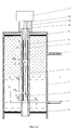
- a type of liquid level gauge for continuous measurement of a boiler steam drum under all conditions and the liquid level gauge for a boiler steam drum mentioned includes a metal measurement tube and a transmitter.
- the steam-side pipe connected to the steam drum is fitted on the upper part of the metal measurement tube mentioned and the water-side pipe connected to steam drum is fitted on the lower part of the metal measurement tube mentioned, an insulated jacket pipe is provided inside the metal measurement tube mentioned, a 1# probe, a 2# probe, and a 3# probe are mounted in turn from bottom to top inside the insulated jacket pipe mentioned, and the respective probes are mutually insulated and are not conducted.
- the three probes mentioned are respectively connected with the transmitter through lead wires.
- the lead wires for the probes mentioned are the shielded conducting wires, the core on one end of the shielded conducting wire is connected with the probe, and the core on the other end of the shielded conducting wire mentioned and the shielding layer are connected to the transmitter.
- the three probes mentioned measure capacitance by turns, and both the other probes will stop measurement at the same time when any of the three probes is measuring the capacitance.
- the parameters calibrated for the liquid level gauge are used, to measure the capacitance values of the 1# probe, the 2# probe, and the 3# probe during the work of the gauge, and the 1# probe and the 3# probe are used to respectively monitor the dielectric constants of water and steam.
- the parameters calibrated for the liquid level gauge are used, to measure the capacitance values of the 1# probe, the 2# probe, and the 3# probe during operation of the gauge, the 1# probe and the 3# probe are used to respectively monitor the dielectric constants of water and steam, and the capacitances of null value Ce1, Ce2, and Ce3 as well as the capacitances of full value Cm1, Cm2, and Cm3 are used to calculate and get the mapping heights of the 1# probe and the 3# probe relative to the 2# probe.
- H ⁇ 12 Cm ⁇ 1 - Ce ⁇ 1 Cm ⁇ 2 - Ce ⁇ 2 ⁇ H ⁇ 2
- H ⁇ 32 Cm ⁇ 3 - Ce ⁇ 3 Cm ⁇ 2 - Ce ⁇ 2 ⁇ H ⁇ 2
- the beneficial effect of this invention is: As the changes in water and steam dielectric constants are only reflected for the situations of boiler startup, boiler shutdown, and boiler joint discharge, etc. as far as the liquid level gauge is concerned, while this liquid level gauge for a boiler steam drum is able to monitor the dielectric constants of water and steam in a real-time manner, the liquid level values can be outputted reliably and accurately in a continuous way with the liquid level gauge for a boiler steam drum designed according to this invention in all cases, no matter if the boiler is under startup and shutdown, or joint discharge status, thus to achieve the function of continuous measurement of liquid levels under all conditions.
- H1, H2, and H3 are respectively the physical heights of the 1# probe, the 2# probe, and the 3# probe
- E1 is the distance from the lower end of the 1# probe to the centerline of the water-side pipe of steam drum
- E2 and E3 are the clearances between the 1# probe and the 2# probe and between the 2# probe and the 3# probe, respectively.
- L is the range of the liquid level gauge, namely the center distance of the boiler water-side pipe and the steam-side pipe.
- H1 100mm
- H2 400mm
- H3 150mm
- E1 0
- the liquid level gauge mentioned for a boiler steam drum includes a metal measurement tube 4 and a transmitter 11.
- the steam-side pipe 2 connected to the steam drum is fitted on the upper part of the metal measurement tube mentioned and the water-side pipe 1 connected to steam drum is fitted on the lower part of the metal measurement tube mentioned, an insulated jacket pipe 8 is provided inside the metal measurement tube mentioned, a 1# probe 5, a 2# probe 6, and a 3# probe 7 are mounted in turn from bottom to top inside the insulated jacket pipe mentioned, and respective probes are mutually insulated and not conducted, of which the 1# probe is mainly used for monitoring the dielectric constant of water, the 3# probe is mainly used for monitoring the dielectric constant of steam, and the 2# probe is the main measurement probe.
- the three probes mentioned are respectively connected with the transmitter 11 through the lead wires 10.
- the lead wire 10 of the probe is a shielded conducting wire
- the core on one end of the shielded conducting wire is connected with the probe and the core on the other end of the shielded conducting wire and the shielding layer are connected with the transmitter.
- the three probes undertake the measurement by turns.
- the 1# probe is making measurement
- the 2# and 3# probes stop measurement
- the 1# and 3# probes stop measurement
- the 3# probe is making measurement
- an insulated jacket 8 is provided inside the metal measurement tube 4, and both the upper part and the lower part of the metal measurement tube 4 are insulated.
- three measurement probes are provided from bottom to top: a 1# probe 5, a 2# probe 6, and a 3# probe 7, and these three probes are mutually insulated and not conducted.
- the core on one end of the three shielded conducting wires is respectively connected to the three probes, and the core on the other end and the shielding layer are connected to the transmitter 11, thus the three probes have formed three capacitances respectively with the metal measurement tube.
- Transmitter 11 is used for measuring the three values of the capacitances, to calculate the liquid level values, to output the simulated current signals of liquid level and digital communication signals of liquid level.
- the transmitter 11 is built-in with single chip microcomputer, capacitance measurement, current transformation and transmission, digital communication interface, and other circuits.
- the microcomputer fulfills signal processing for capacitance measurement, calculation of the liquid level value, output of current value, digital communication, and other tasks.
- the transmitter calculates the liquid level value through measurement of the three capacitance values between the three probes and the metal measurement tube and outputs the simulated current signal of liquid level through a current transmission circuit, for digital communication to be performed on digital communication interface and master computer.
- Two connecting pipes namely the steam-side pipe 2 and the water-side pipe 1 are led out from the metal measurement tube, and the steam-side pipe 2 and the water-side pipe 1 are respectively connected to the steam-side pipe and the water-side pipe of the steam drum, to measure out the liquid level inside the measurement tube, to rightly get the liquid level inside the steam drum, according to the principle of a connected vessel.
- heat insulation measures shall be applied to the outside of the measurement tube, so that the temperatures of water and steam inside the measurement tube are approximate to the temperatures of water and steam inside the steam drum, thus to reduce the error of liquid level caused by density difference.
- the method for calculation of liquid level with the liquid level gauge for continuous measurement of boiler steam drum under all conditions is:
- the liquid level gauge calibrated through the abovementioned parameters calculates the liquid level value Hx after one group of capacitance values (Cx1, Cx2, and Cx3) is measured each time during operation of the gauge.
- the method for calculation of liquid level with the liquid level gauge for continuous measurement of boiler steam drum under all conditions is:
Landscapes
- Physics & Mathematics (AREA)
- Engineering & Computer Science (AREA)
- Power Engineering (AREA)
- Thermal Sciences (AREA)
- Electromagnetism (AREA)
- Fluid Mechanics (AREA)
- General Physics & Mathematics (AREA)
- Mechanical Engineering (AREA)
- General Engineering & Computer Science (AREA)
- Measurement Of Levels Of Liquids Or Fluent Solid Materials (AREA)
Applications Claiming Priority (2)
| Application Number | Priority Date | Filing Date | Title |
|---|---|---|---|
| CN200710163870A CN100590397C (zh) | 2007-10-10 | 2007-10-10 | 全工况连续测量锅炉汽包液位计及其液位计算方法 |
| PCT/CN2007/003012 WO2009046579A1 (fr) | 2007-10-10 | 2007-10-22 | Limnimètre de mesure de liquide en continu sous toutes conditions pour un ballon de vapeur d'une chaudière et son procédé de mesure de niveau de liquide correspondant |
Publications (2)
| Publication Number | Publication Date |
|---|---|
| EP2199760A1 true EP2199760A1 (fr) | 2010-06-23 |
| EP2199760A4 EP2199760A4 (fr) | 2012-11-28 |
Family
ID=40548934
Family Applications (1)
| Application Number | Title | Priority Date | Filing Date |
|---|---|---|---|
| EP07816625A Withdrawn EP2199760A4 (fr) | 2007-10-10 | 2007-10-22 | Limnimètre de mesure de liquide en continu sous toutes conditions pour un ballon de vapeur d'une chaudière et son procédé de mesure de niveau de liquide correspondant |
Country Status (5)
| Country | Link |
|---|---|
| US (1) | US8272264B2 (fr) |
| EP (1) | EP2199760A4 (fr) |
| CN (1) | CN100590397C (fr) |
| RU (1) | RU2424495C1 (fr) |
| WO (1) | WO2009046579A1 (fr) |
Cited By (2)
| Publication number | Priority date | Publication date | Assignee | Title |
|---|---|---|---|---|
| CN102840897A (zh) * | 2011-06-22 | 2012-12-26 | 河南长润自动化系统有限公司 | 一种带有水蒸汽冷凝室的锅炉汽包液位计 |
| WO2015028306A1 (fr) * | 2013-08-28 | 2015-03-05 | Sulzer Management Ag | Sonde pour surveiller le niveau de la surface d'un fluide dans un récipient et procédé d'installation de la sonde dans le récipient |
Families Citing this family (24)
| Publication number | Priority date | Publication date | Assignee | Title |
|---|---|---|---|---|
| US20120067119A1 (en) * | 2009-05-26 | 2012-03-22 | Diba Industries, Inc. | Pressure-sensor based liquid-level measuring device with reduced capillary effect |
| US8630814B2 (en) | 2011-01-31 | 2014-01-14 | Xylem IP Holdings LLC. | Ultrasonic water level gauge and control device |
| CN102606877B (zh) * | 2012-03-31 | 2014-02-12 | 贾林祥 | 一种液化天然气气瓶的液面测量装置 |
| CN102840896B (zh) * | 2012-09-05 | 2015-06-10 | 中国石油化工集团公司 | 一种液位测量装置 |
| CN103528642B (zh) * | 2013-10-07 | 2016-09-07 | 北京航天试验技术研究所 | 一种实时修正介电常数的电容式液位计及其液位测量方法 |
| CN103759788A (zh) * | 2014-01-03 | 2014-04-30 | 莱芜钢铁集团有限公司 | 一体化锅炉汽包液位计及液位测量方法 |
| CN105157788A (zh) * | 2015-05-07 | 2015-12-16 | 四川科强电子技术有限责任公司 | 检测液压式cng加气子站“溢油”的高速高压液位计 |
| CN106768177A (zh) * | 2017-03-22 | 2017-05-31 | 潍坊通达仪表有限公司 | 液位传感器、传感器系统和液位高度测量方法 |
| RU2651638C1 (ru) * | 2017-05-16 | 2018-04-23 | ООО предприятие "КОНТАКТ-1" | Способ измерения уровня границы раздела сред инвариантный к величине диэлектрической проницаемости сред |
| DE102017111393A1 (de) * | 2017-05-24 | 2018-11-29 | Endress+Hauser SE+Co. KG | Verfahren zur Prozessüberwachung |
| CN107806917B (zh) * | 2017-12-06 | 2023-09-26 | 秦皇岛华电测控设备有限公司 | 高精度云母水位计 |
| CN107843312A (zh) * | 2017-12-19 | 2018-03-27 | 国丰新能源江苏有限公司 | 测量波动大介质液位的浸入式液位计 |
| CN109297563B (zh) * | 2018-11-15 | 2024-02-23 | 河南菲普斯特仪器仪表有限公司 | 一种用于狭小空间液压油测量方法及其装置 |
| CN109855084B (zh) * | 2018-12-31 | 2024-03-19 | 中国能源建设集团华东电力试验研究院有限公司 | 锅炉补给水液位计测量数值跳变消除系统及控制方法 |
| CN110231071B (zh) * | 2019-07-17 | 2020-08-11 | 湖北保乾科技有限公司 | 一种基于电容式传感器的液位测量装置 |
| CN110646061A (zh) * | 2019-09-17 | 2020-01-03 | 高海 | 一种双路冗余智能校准射频导纳防溢液位计及其测量方法 |
| CN112050903A (zh) * | 2020-08-17 | 2020-12-08 | 福建福清核电有限公司 | 导波雷达液位计蒸汽补偿方法和装置 |
| CN112283698A (zh) * | 2020-11-18 | 2021-01-29 | 福士德锅炉有限公司 | 一种探针式变频连续补水装置及控制方法 |
| CN113144339B (zh) * | 2021-04-13 | 2023-08-01 | 山东亚华电子股份有限公司 | 一种输液监测装置 |
| CN118103239A (zh) * | 2021-10-15 | 2024-05-28 | 海拉有限双合股份公司 | 冷却剂箱、冷却剂引导系统和机动车 |
| CN116576939A (zh) * | 2023-05-08 | 2023-08-11 | 祁世宽 | 测量仪表及其安装方法 |
| CN116659617A (zh) * | 2023-05-22 | 2023-08-29 | 潍坊通达仪表有限公司 | 一种多电极电容传感器测量液位高度的计算方法 |
| CN121026273B (zh) * | 2025-09-09 | 2026-03-31 | 广东龙宇新材料有限公司 | 一种含浸机树脂液位智能感知与预警方法 |
| CN121655647B (zh) * | 2026-02-06 | 2026-04-10 | 山东通达仪表科技有限公司 | 一种无线液位远程监测液位计及监测系统 |
Family Cites Families (20)
| Publication number | Priority date | Publication date | Assignee | Title |
|---|---|---|---|---|
| DE2924556A1 (de) * | 1979-06-19 | 1981-01-22 | Eaton Gmbh | Fuellstandsanzeigeeinrichtung |
| GB8412460D0 (en) * | 1984-05-16 | 1984-06-20 | Schlumberger Electronics Uk | Fluid level measurement |
| GB8501805D0 (en) * | 1985-01-24 | 1985-02-27 | Ward Ind Plant Ltd T W | Water level controller |
| DE3541613A1 (de) * | 1985-11-25 | 1987-05-27 | Kraftwerk Union Ag | Verfahren und einrichtung zur messung des fuellstandes in einem reaktordruckbehaelter eines siedewasserreaktors |
| US5131264A (en) * | 1989-07-25 | 1992-07-21 | Mobil Oil Corporation | Above-ground storage tank liquid leak detector |
| US5038611A (en) * | 1989-12-20 | 1991-08-13 | Westinghouse Electric Corp. | Apparatus and method for providing a temperature compensated liquid level measurement |
| US5103368A (en) * | 1990-05-07 | 1992-04-07 | Therm-O-Disc, Incorporated | Capacitive fluid level sensor |
| US6101873A (en) * | 1996-05-17 | 2000-08-15 | Nohken Inc. | Level sensor |
| AU8076198A (en) * | 1997-01-28 | 1998-08-18 | Abb Research Ltd | Capacitative level detector with optimized electrode geometry |
| DE19713267A1 (de) * | 1997-01-28 | 1998-07-30 | Abb Research Ltd | Verfahren zur Bestimmung der Dielektrizitätskonstante und/oder der Leitfähigkeit mindestens eines Mediums sowie Vorrichtung zur Durchführung des Verfahrens |
| JP4182620B2 (ja) * | 2000-05-15 | 2008-11-19 | 株式会社Ihi | ボイラのドラムレベル計測装置 |
| WO2002003039A1 (fr) * | 2000-06-30 | 2002-01-10 | Clark-Reliance Corporation | Controleur de niveau automatique pour chaudiere |
| CN2436919Y (zh) * | 2000-07-15 | 2001-06-27 | 高维信 | 汽包水位高精度取样电极传感器 |
| US6761067B1 (en) * | 2002-06-13 | 2004-07-13 | Environment One Corporation | Scanning capacitive array sensor and method |
| CN1506665A (zh) * | 2002-12-12 | 2004-06-23 | 陈延平 | 锅炉汽包水位真值的测量方法及水位计 |
| CN1189724C (zh) * | 2003-04-08 | 2005-02-16 | 罗明 | 具有实现液位测量自动补偿的三探头电容式液位计测量筒 |
| US7062965B2 (en) * | 2004-07-29 | 2006-06-20 | General Motors Corporation | Resistive level sensor for cryo-liquid gas tanks |
| US6932028B1 (en) * | 2004-10-06 | 2005-08-23 | Vogt Power International Inc. | Apparatus and method for determining a liquid level in a steam drum |
| CN2819057Y (zh) * | 2004-11-01 | 2006-09-20 | 郭程鹏 | 一种电极式水位计 |
| CN100460833C (zh) * | 2006-11-15 | 2009-02-11 | 高维信 | 汽包水位单筒式高精度电极测量筒及其几何尺寸确定方法 |
-
2007
- 2007-10-10 CN CN200710163870A patent/CN100590397C/zh active Active
- 2007-10-22 RU RU2009142048/28A patent/RU2424495C1/ru active
- 2007-10-22 US US12/531,490 patent/US8272264B2/en active Active
- 2007-10-22 EP EP07816625A patent/EP2199760A4/fr not_active Withdrawn
- 2007-10-22 WO PCT/CN2007/003012 patent/WO2009046579A1/fr not_active Ceased
Cited By (4)
| Publication number | Priority date | Publication date | Assignee | Title |
|---|---|---|---|---|
| CN102840897A (zh) * | 2011-06-22 | 2012-12-26 | 河南长润自动化系统有限公司 | 一种带有水蒸汽冷凝室的锅炉汽包液位计 |
| CN102840897B (zh) * | 2011-06-22 | 2014-08-27 | 河南长润自动化系统有限公司 | 一种带有水蒸汽冷凝室的锅炉汽包液位计 |
| WO2015028306A1 (fr) * | 2013-08-28 | 2015-03-05 | Sulzer Management Ag | Sonde pour surveiller le niveau de la surface d'un fluide dans un récipient et procédé d'installation de la sonde dans le récipient |
| US9752916B2 (en) | 2013-08-28 | 2017-09-05 | Sulzer Management Ag | Probe for monitoring the surface level of a fluid in a vessel and a method of installing the probe in the vessel |
Also Published As
| Publication number | Publication date |
|---|---|
| EP2199760A4 (fr) | 2012-11-28 |
| WO2009046579A1 (fr) | 2009-04-16 |
| CN101408450A (zh) | 2009-04-15 |
| US8272264B2 (en) | 2012-09-25 |
| RU2424495C1 (ru) | 2011-07-20 |
| RU2009142048A (ru) | 2011-05-27 |
| CN100590397C (zh) | 2010-02-17 |
| US20100180679A1 (en) | 2010-07-22 |
Similar Documents
| Publication | Publication Date | Title |
|---|---|---|
| EP2199760A1 (fr) | Limnimètre de mesure de liquide en continu sous toutes conditions pour un ballon de vapeur d'une chaudière et son procédé de mesure de niveau de liquide correspondant | |
| CN106940215B (zh) | 一种智能补偿内置式汽包液位测量装置 | |
| CN203148514U (zh) | 电容式自适应液位传感器 | |
| CN107462306A (zh) | 一种燃油加油机自动检定装置 | |
| CN106404112A (zh) | 一种电容式液位传感器的免标定测量方法和装置 | |
| CN105466521A (zh) | 一种容器中液体液位的测量方法 | |
| CN111220236A (zh) | 一种大直径泥水盾构机的气垫仓防爆型液位检测装置 | |
| CN108204846A (zh) | 飞机油量测量系统免校准设计方法 | |
| CN203396459U (zh) | 一种自校准的电容式液位传感器 | |
| CN211013137U (zh) | 锅炉汽包液位计 | |
| CN219996274U (zh) | 一种可自校准的秸秆料仓料位检测装置 | |
| CN107796492B (zh) | 一种超声波燃气表在线式校准方法 | |
| CN202133437U (zh) | 自校准投入式压力液位计 | |
| CN106441496A (zh) | 一种液位测量方法 | |
| CN205843649U (zh) | 一种输电塔架弯曲度测量仪 | |
| CN108572020B (zh) | 一种电极式液位计 | |
| CN111521876B (zh) | 一种容性设备在线监测方法和装置 | |
| CN102928050A (zh) | 一种无测量盲区的多段导纳液位界面仪 | |
| CN118090516A (zh) | 一种plc双探头压力差分黄河浑水含沙量快速测定方法 | |
| CN102401679A (zh) | 一种一体式智能液位计 | |
| CN206114054U (zh) | 一种实验用高精度无线数字水深传感器系统 | |
| CN207366045U (zh) | 一种燃煤电厂水位测量装置 | |
| CN203258369U (zh) | 内置一体的子母电容式传感器 | |
| JP7813449B2 (ja) | 静電容量式レベル測定装置及び静電容量式レベル測定方法 | |
| CN115950502B (zh) | 实时自校正管网液位检测方法及检测装置 |
Legal Events
| Date | Code | Title | Description |
|---|---|---|---|
| PUAI | Public reference made under article 153(3) epc to a published international application that has entered the european phase |
Free format text: ORIGINAL CODE: 0009012 |
|
| 17P | Request for examination filed |
Effective date: 20100211 |
|
| AK | Designated contracting states |
Kind code of ref document: A1 Designated state(s): AT BE BG CH CY CZ DE DK EE ES FI FR GB GR HU IE IS IT LI LT LU LV MC MT NL PL PT RO SE SI SK TR |
|
| AX | Request for extension of the european patent |
Extension state: AL BA HR MK RS |
|
| DAX | Request for extension of the european patent (deleted) | ||
| A4 | Supplementary search report drawn up and despatched |
Effective date: 20121031 |
|
| RIC1 | Information provided on ipc code assigned before grant |
Ipc: F22B 37/78 20060101ALI20121025BHEP Ipc: G01F 23/26 20060101AFI20121025BHEP |
|
| STAA | Information on the status of an ep patent application or granted ep patent |
Free format text: STATUS: THE APPLICATION HAS BEEN WITHDRAWN |
|
| 18W | Application withdrawn |
Effective date: 20160929 |