EP2199828A2 - Procédé de détermination de la position relative d'un scanner laser par rapport à un système de référence - Google Patents
Procédé de détermination de la position relative d'un scanner laser par rapport à un système de référence Download PDFInfo
- Publication number
- EP2199828A2 EP2199828A2 EP09450183A EP09450183A EP2199828A2 EP 2199828 A2 EP2199828 A2 EP 2199828A2 EP 09450183 A EP09450183 A EP 09450183A EP 09450183 A EP09450183 A EP 09450183A EP 2199828 A2 EP2199828 A2 EP 2199828A2
- Authority
- EP
- European Patent Office
- Prior art keywords
- laser scanner
- image
- scanning plane
- spatial
- surrounding area
- Prior art date
- Legal status (The legal status is an assumption and is not a legal conclusion. Google has not performed a legal analysis and makes no representation as to the accuracy of the status listed.)
- Granted
Links
Images


Classifications
-
- G—PHYSICS
- G01—MEASURING; TESTING
- G01S—RADIO DIRECTION-FINDING; RADIO NAVIGATION; DETERMINING DISTANCE OR VELOCITY BY USE OF RADIO WAVES; LOCATING OR PRESENCE-DETECTING BY USE OF THE REFLECTION OR RERADIATION OF RADIO WAVES; ANALOGOUS ARRANGEMENTS USING OTHER WAVES
- G01S17/00—Systems using the reflection or reradiation of electromagnetic waves other than radio waves, e.g. lidar systems
- G01S17/88—Lidar systems specially adapted for specific applications
- G01S17/89—Lidar systems specially adapted for specific applications for mapping or imaging
-
- G—PHYSICS
- G01—MEASURING; TESTING
- G01S—RADIO DIRECTION-FINDING; RADIO NAVIGATION; DETERMINING DISTANCE OR VELOCITY BY USE OF RADIO WAVES; LOCATING OR PRESENCE-DETECTING BY USE OF THE REFLECTION OR RERADIATION OF RADIO WAVES; ANALOGOUS ARRANGEMENTS USING OTHER WAVES
- G01S17/00—Systems using the reflection or reradiation of electromagnetic waves other than radio waves, e.g. lidar systems
- G01S17/02—Systems using the reflection of electromagnetic waves other than radio waves
- G01S17/06—Systems determining position data of a target
- G01S17/46—Indirect determination of position data
- G01S17/48—Active triangulation systems, i.e. using the transmission and reflection of electromagnetic waves other than radio waves
-
- G—PHYSICS
- G01—MEASURING; TESTING
- G01S—RADIO DIRECTION-FINDING; RADIO NAVIGATION; DETERMINING DISTANCE OR VELOCITY BY USE OF RADIO WAVES; LOCATING OR PRESENCE-DETECTING BY USE OF THE REFLECTION OR RERADIATION OF RADIO WAVES; ANALOGOUS ARRANGEMENTS USING OTHER WAVES
- G01S5/00—Position-fixing by co-ordinating two or more direction or position line determinations; Position-fixing by co-ordinating two or more distance determinations
- G01S5/16—Position-fixing by co-ordinating two or more direction or position line determinations; Position-fixing by co-ordinating two or more distance determinations using electromagnetic waves other than radio waves
-
- G—PHYSICS
- G01—MEASURING; TESTING
- G01S—RADIO DIRECTION-FINDING; RADIO NAVIGATION; DETERMINING DISTANCE OR VELOCITY BY USE OF RADIO WAVES; LOCATING OR PRESENCE-DETECTING BY USE OF THE REFLECTION OR RERADIATION OF RADIO WAVES; ANALOGOUS ARRANGEMENTS USING OTHER WAVES
- G01S7/00—Details of systems according to groups G01S13/00, G01S15/00, G01S17/00
- G01S7/48—Details of systems according to groups G01S13/00, G01S15/00, G01S17/00 of systems according to group G01S17/00
- G01S7/497—Means for monitoring or calibrating
- G01S7/4972—Alignment of sensor
Definitions
- the present invention relates to a method for determining the relative position of a laser scanner, which detects a 2D profile of its surroundings in a scanning plane and is carried by a conveyor in a scanning plane-foreign direction to create a 3D image of the environment, relative to a Reference system of the means of transport.
- Laser scanners of this type are for example from the GB 2 434 269 A known and used for terrestrial land surveying in the form of so-called mobile scanning or mobile mapping.
- the topography of the landscape is detected by a moving land or water vehicle, which carries the laser scanner.
- Mobile scanning systems are much less expensive than airborne or satellite-based surveying systems and, moreover, can detect inaccessible areas from the air, such as streets, waterways, tunnels, mining structures, etc.
- trajectory and orientation of the vehicle summarized here under the term "trajectory”, as well as the location of the laser scanner on the vehicle are well known.
- trajectory can lead to significant surveying errors over the long paths to be traveled by the scanning beams.
- a vehicle-mounted inertial measurement unit (IMU) in conjunction with a global navigation satellite system (GNSS) is usually used as a reference system for the movement.
- the relative position of the laser scanner relative to the reference system must hitherto be adjusted by means of calibration measurements in a controlled measuring environment with defined measuring distances and points.
- GNSS global navigation satellite system
- the method of the invention is based on the finding that an angular offset in the relative position of the laser scanner relative to the motion reference system in two scan passes with different angular positions of the scanning reflected in an angular offset of the two 3D images, which can be measured and a direct inference to the relative position allows.
- the method of the invention requires no special reference or measuring environment, but can be carried out directly on site without additional aids. This allows both a quick initial assembly and a quick replacement of the laser scanner for repair purposes, for a temporary other use of the laser scanner far away from the conveyor or for a modular change of different laser scanners on a particular means of conveyance without compromising the accuracy of imaging.
- the change in the scanning plane of the laser scanner can be achieved in various ways.
- the laser scanner can emit two electronically or optically switchable jet fans, or even a single beam fan, which can be brought into different angular positions by means of a mechanical pivotal mounting of the laser scanner.
- at least one controllable 3D laser scanner is used as the laser scanner.
- a 3D laser scanner generates a beam fan in a scanning plane for detecting a 2D profile and, on the other hand, rotates about an additional axis in order to generate a 3D image of the environment via the selected rotation angle from a large number of 2D profiles.
- the use of such a 3D laser scanner has the advantage that the respective angular position of the scanning plane is particularly well known due to the device's already existing mechatronics for angle control and the axis of rotation coincides exactly with the scanner axis.
- Determining said relative position from a comparison of the spatial position of the object in the further 3D image with at least one of the previously determined spatial positions.
- the scanning plane is pivoted into numerous successive angular positions, whereby a higher spatial resolution can be achieved when the conveyor is stationary, which facilitates the object identification in the 3D images.
- An implementation technology particularly favorable embodiment of the method is characterized in that in the mentioned comparisons, the relative position of the solid angle difference of the spatial positions of a selected spatial axis of the object, adjusted for the aforementioned direction of travel and angular position changes between the various 3D images, is determined.
- an area detected in the environment is selected as the object, and its surface normal as said spatial axis, whereby implementations with particularly short computation times can be achieved.
- the laser scanner is mounted interchangeably on the means of transport via a quick attachment, which allows a rapid change of the laser scanner in the field.
- Fig. 1 shows a means of transport 1 in the form of an off-road vehicle with a roof rack on which a reference system 2 and a laser scanner 3 are mounted.
- the means of conveyance 1 moves along a trajectory 4, each with a current direction of travel 5.
- the reference system 2 determines the current (time-dependent) driving direction 5, for example with the aid of an inertia measuring system (IMU) and / or a satellite navigation system (GNSS) and thus the trajectory 4 of the means of transport 1 in a world coordinate system 6 to provide therefrom a (time dependent) reference coordinate system 7 for the scan, as known in the art.
- IMU inertia measuring system
- GNSS satellite navigation system
- the means of transport 1 may also be any other land, air or water vehicle, both powered by motor and muscle, e.g. a truck, a rail vehicle, a boat, a lorry, a trolley or, in the simplest case, just a stretcher.
- the laser scanner 3 transmits a laser beam fan to an environment 9 in a scanning plane 8 in order to detect a 2D profile 10 of the surroundings 9 from the reflection of the laser beam fan.
- a 3D image of the environment 9 is thus created from a plurality of successive 2D profiles 10 and stored, for example, in a memory of the laser scanner 3.
- the trajectory 4 of the conveyor 1 determined by the reference system 2 is taken into account - or even later in a later offline evaluation of the scanner raw data in order to adjust the movements of the 2D profiles 10 detected in the reference coordinate system 7. as a correct 3D image of the environment 9 in the world coordinate system 6 build.
- the laser scanner 3 is mounted in a housing and mounted on the conveyor means 1 modular interchangeable by means of a snap fastener 11 acting thereon, for example in the form of a lockable insertion bracket.
- the relative position of the laser scanner 3 relative to the reference system 2 is thus subject to housing storage and assembly tolerances, which are not known in advance;
- the laser scanner 3 thus has its own coordinate system 12. Consequently, the correct structure of the 3D image of the environment 9 in the world coordinate system 6 is also known to the relative position of the laser scanner 3 relative to the reference system 2, ie the position of the coordinate system 12 relative to the coordinate system 7, and this is now determined as follows.
- the conveyor 1 is moved in a first direction of travel 5 and the scanning plane 8 of the laser scanner 3 is held in a first angular position in order to produce a first 3D image 13 (FIG. Fig. 4 ) of a selected area 9 'of the environment 9.
- the transport means 1 in a second direction of travel 5 '(here: opposite) along the same area 9' moves and the scanning plane 8 in a second angular position (here: turned by 180 °) held to a second 3D image 14 (FIG. Fig. 4 ) of the same environment area 9 '.
- One and the same object 15 is now identified in the two 3D images 13, 14, for example by pattern detection methods of a type known per se.
- the object is a flat region of a building front.
- the respective spatial position of the object 15 is determined in the 3D images 13, 14, u.zw.
- a surface is selected as the object 15, and the surface normals 16, 17 of the object 15 in the 3D images 13, 14 indicate its respective spatial position, see FIG Fig. 4 ,
- a relative offset of the laser scanner 3 relative to the reference system 2 e.g. a solid angle difference 18 between the axis 19 of the coordinate system 12 and the axis 20 of the coordinate system 7, is reflected in a spatial angle difference 21 of the spatial axes 16 and 17 of the object 15 in the 3D images 13, 14 down.
- This can be concluded from a comparison of the spatial positions of the object 15 in the 3D images 13, 14 on the relative position between the laser scanner 3 and the reference system 2.
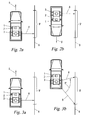
- the second direction of travel 5 'of the first direction of travel 5 and the second angular position of the scanning plane 8 The first angular position is exactly opposite by 180 ° and the directions of travel 5, 5 'are parallel to a planar object 15 ( Fig. 2a, 2b). If, on the other hand, the directions of travel 5, 5 'and the angular positions of the scanning plane 8 deviate from this case, the spatial positions of the object determined in the 3D images 13, 14 need to be determined 15 only to be compensated for the respective direction of travel and angular position deviations in order to obtain exclusively the spatial angle difference 18 due to the angular offset of the laser scanner 3 relative to the reference system 2.
- the first and / or second scan passes the Fig. 2a and 2b also in each case in a direction obliquely to the surrounding area 9 'running direction 5, 5' and / or carried out with non-rectangular angular positions of the scanning plane 8.
- a planar object 15 could also be defined merely by three arbitrary, significant points 22, 23, 24 in the surroundings 9.
- the 3D images 13, 14 could be reduced in their spatial resolution, if desired, to those 2D profiles 10 which contain or surround these points, provided that a corresponding selection of the points and / or pre-adjustment of the scanning plane 8 to certain points in the environment 9 is possible.
- the Fig. 3a and 3b show a further process variant in which in the first step ( Fig. 3a ) the transport means 1 is moved in a first direction of travel 5 along the surrounding area 9 'in order to produce the first 3D image 13, while in the second step ( Fig. 3b ) the conveyor 1 is stopped and the scanning plane 8 of the laser scanner 3 is brought into different angular positions, see arrow 5 ", to produce from the same surrounding area 9 'the second 3D image 14.
- the second 3D image 14 is compensated by the pivot angle (arrow 5 "), ie equalized.
- the process step of Fig. 3b can also before the step of Fig. 3a be executed.
- the direction of travel 5 in the step of Fig. 3a , the stop position of the conveyor 1 in the step of Fig. 3b and / or the angular positions of the scan planes 8 may also be selected differently than shown, as already discussed.
- Fig. 5 shows such an alternative embodiment, which carries three 3D laser scanners 3, 3 ', 3 "with pivotable scanning planes 8, 25, 26 in vertical directions to both sides of the conveyor 1 and two 2D laser scanners 27, 28, one of which Rear of the means of transport 1 a vertical fan-fold 29 and the other a obliquely forward up or down directed laser fan 30 radiates.
- Each of the other laser scanners 3 ', 3 ", 27 and 28 has - analogously to the laser scanner 3 in FIG Fig. 1 with its coordinate system 12 - via its own (not shown here) coordinate system, which may be misaligned with respect to the laser scanner 3 and / or the reference system 2.
- the described methods can be used in cascade: As in FIG Fig. 6
- a further 3D image 31 of the surrounding area 9 ' is created for each further laser scanner, eg by moving it down in accordance with FIGS Fig. 2a and 2b or swinging in accordance with the Fig. 3a and 3b , and in the object 15 is detected again.
- the relative position of each further laser scanner 3 ', 3 ", 27 and 28 relative to the laser scanner 3 and / or the reference system 2 can now be determined.
Landscapes
- Physics & Mathematics (AREA)
- Engineering & Computer Science (AREA)
- Electromagnetism (AREA)
- General Physics & Mathematics (AREA)
- Radar, Positioning & Navigation (AREA)
- Remote Sensing (AREA)
- Computer Networks & Wireless Communication (AREA)
- Length Measuring Devices By Optical Means (AREA)
Applications Claiming Priority (1)
| Application Number | Priority Date | Filing Date | Title |
|---|---|---|---|
| AT0184608A AT507618B1 (de) | 2008-11-26 | 2008-11-26 | Verfahren zum bestimmen der relativlage eines laserscanners zu einem referenzsystem |
Publications (3)
| Publication Number | Publication Date |
|---|---|
| EP2199828A2 true EP2199828A2 (fr) | 2010-06-23 |
| EP2199828A3 EP2199828A3 (fr) | 2010-12-01 |
| EP2199828B1 EP2199828B1 (fr) | 2011-12-28 |
Family
ID=41718468
Family Applications (1)
| Application Number | Title | Priority Date | Filing Date |
|---|---|---|---|
| EP09450183A Active EP2199828B1 (fr) | 2008-11-26 | 2009-09-24 | Procédé de détermination de la position relative d'un scanner laser par rapport à un système de référence |
Country Status (2)
| Country | Link |
|---|---|
| EP (1) | EP2199828B1 (fr) |
| AT (2) | AT507618B1 (fr) |
Cited By (10)
| Publication number | Priority date | Publication date | Assignee | Title |
|---|---|---|---|---|
| WO2012012819A1 (fr) * | 2010-07-26 | 2012-02-02 | Commonwealth Scientific And Industrial Research Organisation | Système de faisceau de balayage tridimensionnel et procédé associé |
| JP2015212942A (ja) * | 2014-04-25 | 2015-11-26 | グーグル インコーポレイテッド | レーザー点クラウドを用いる物体検出のための方法及びシステム |
| JP2016001182A (ja) * | 2015-07-21 | 2016-01-07 | コモンウェルス サイエンティフィック アンド インダストリアル リサーチ オーガナイゼーション | 3次元走査ビーム・システムおよび方法 |
| DE102016225595A1 (de) * | 2016-12-20 | 2018-06-21 | Siemens Aktiengesellschaft | Verfahren und Anordnung zur Kalibrierung mindestens eines Sensors eines Schienenfahrzeugs |
| DE102018208080B3 (de) | 2018-05-23 | 2019-09-19 | Kuka Deutschland Gmbh | Verfahren und System zum Lokalisieren eines Objekts in einer Umgebung eines Roboters |
| WO2019193207A1 (fr) | 2018-04-06 | 2019-10-10 | Navvis Gmbh | Dispositif mobile et procédé de détection d'un espace objet |
| EP3739291A1 (fr) | 2019-05-17 | 2020-11-18 | Hexagon Technology Center GmbH | Procédé de détermination automatique de la position et de l'orientation pour un balayeur laser terrestre |
| CN113552580A (zh) * | 2020-04-17 | 2021-10-26 | 上海禾赛科技有限公司 | 激光雷达以及使用该激光雷达进行目标物探测的方法 |
| US11604065B2 (en) | 2019-05-17 | 2023-03-14 | Hexagon Technology Center Gmbh | Fully automatic position and alignment determination method for a terrestrial laser scanner and method for ascertaining the suitability of a position for a deployment for surveying |
| DE102022102322A1 (de) | 2022-02-01 | 2023-08-03 | Bayerische Motoren Werke Aktiengesellschaft | Verfahren zur korrektur eines bauartbedingten abbildungsfehlers eines lidar-sensors, recheneinrichtung, lidar-sensorsystem, computerprogramm sowie computerlesbares (speicher)medium |
Citations (1)
| Publication number | Priority date | Publication date | Assignee | Title |
|---|---|---|---|---|
| GB2434269A (en) | 2006-01-17 | 2007-07-18 | 3D Laser Mapping Ltd | Laser measuring apparatus and position determining device for surveying and route clearance measurement |
Family Cites Families (6)
| Publication number | Priority date | Publication date | Assignee | Title |
|---|---|---|---|---|
| GB2372656A (en) * | 2001-02-23 | 2002-08-28 | Ind Control Systems Ltd | Optical position determination |
| DE102004033114A1 (de) * | 2004-07-08 | 2006-01-26 | Ibeo Automobile Sensor Gmbh | Verfahren zur Kalibrierung eines Abstandsbildsensors |
| JP2010510559A (ja) * | 2006-10-30 | 2010-04-02 | テレ アトラス ベスローテン フエンノートシャップ | 地上モバイルマッピングデータからオブジェクトを検出する方法及び装置 |
| JP2010509585A (ja) * | 2006-11-06 | 2010-03-25 | テレ アトラス ベスローテン フエンノートシャップ | 2次元及び3次元の正確な場所及び方位を判定する装置及び方法 |
| GB2443856A (en) * | 2006-11-18 | 2008-05-21 | Stephen George Nunney | Distance and position measuring system for producing a model of a structure or topography |
| CA2606267A1 (fr) * | 2007-10-11 | 2009-04-11 | Hydro-Quebec | Systeme et methode de cartographie tridimensionnelle d'une surface structurelle |
-
2008
- 2008-11-26 AT AT0184608A patent/AT507618B1/de active
-
2009
- 2009-09-24 EP EP09450183A patent/EP2199828B1/fr active Active
- 2009-09-24 AT AT09450183T patent/ATE539362T1/de active
Patent Citations (1)
| Publication number | Priority date | Publication date | Assignee | Title |
|---|---|---|---|---|
| GB2434269A (en) | 2006-01-17 | 2007-07-18 | 3D Laser Mapping Ltd | Laser measuring apparatus and position determining device for surveying and route clearance measurement |
Cited By (18)
| Publication number | Priority date | Publication date | Assignee | Title |
|---|---|---|---|---|
| CN103180794A (zh) * | 2010-07-26 | 2013-06-26 | 联邦科学和工业研究组织 | 三维扫描束系统和方法 |
| US9146315B2 (en) | 2010-07-26 | 2015-09-29 | Commonwealth Scientific And Industrial Research Organisation | Three dimensional scanning beam system and method |
| CN103180794B (zh) * | 2010-07-26 | 2017-02-15 | 联邦科学和工业研究组织 | 三维扫描束系统和方法 |
| WO2012012819A1 (fr) * | 2010-07-26 | 2012-02-02 | Commonwealth Scientific And Industrial Research Organisation | Système de faisceau de balayage tridimensionnel et procédé associé |
| JP2015212942A (ja) * | 2014-04-25 | 2015-11-26 | グーグル インコーポレイテッド | レーザー点クラウドを用いる物体検出のための方法及びシステム |
| JP2017152049A (ja) * | 2014-04-25 | 2017-08-31 | グーグル インコーポレイテッド | レーザー点クラウドを用いる物体検出のための方法及びシステム |
| JP2016001182A (ja) * | 2015-07-21 | 2016-01-07 | コモンウェルス サイエンティフィック アンド インダストリアル リサーチ オーガナイゼーション | 3次元走査ビーム・システムおよび方法 |
| DE102016225595A1 (de) * | 2016-12-20 | 2018-06-21 | Siemens Aktiengesellschaft | Verfahren und Anordnung zur Kalibrierung mindestens eines Sensors eines Schienenfahrzeugs |
| US12332382B2 (en) | 2018-04-06 | 2025-06-17 | Navvis Gmbh | Mobile apparatus and method for capturing an object space |
| WO2019193207A1 (fr) | 2018-04-06 | 2019-10-10 | Navvis Gmbh | Dispositif mobile et procédé de détection d'un espace objet |
| DE102018108141A1 (de) | 2018-04-06 | 2019-10-10 | Navvis Gmbh | Mobile Vorrichtung und Verfahren zum Erfassen eines Objektraums |
| DE102018208080B3 (de) | 2018-05-23 | 2019-09-19 | Kuka Deutschland Gmbh | Verfahren und System zum Lokalisieren eines Objekts in einer Umgebung eines Roboters |
| US11604065B2 (en) | 2019-05-17 | 2023-03-14 | Hexagon Technology Center Gmbh | Fully automatic position and alignment determination method for a terrestrial laser scanner and method for ascertaining the suitability of a position for a deployment for surveying |
| US11740086B2 (en) | 2019-05-17 | 2023-08-29 | Hexagon Technology Center Gmbh | Method for ascertaining the suitability of a position for a deployment for surveying |
| EP3739291A1 (fr) | 2019-05-17 | 2020-11-18 | Hexagon Technology Center GmbH | Procédé de détermination automatique de la position et de l'orientation pour un balayeur laser terrestre |
| CN113552580A (zh) * | 2020-04-17 | 2021-10-26 | 上海禾赛科技有限公司 | 激光雷达以及使用该激光雷达进行目标物探测的方法 |
| DE102022102322A1 (de) | 2022-02-01 | 2023-08-03 | Bayerische Motoren Werke Aktiengesellschaft | Verfahren zur korrektur eines bauartbedingten abbildungsfehlers eines lidar-sensors, recheneinrichtung, lidar-sensorsystem, computerprogramm sowie computerlesbares (speicher)medium |
| WO2023147961A1 (fr) | 2022-02-01 | 2023-08-10 | Bayerische Motoren Werke Aktiengesellschaft | Procédé de correction d'une aberration liée à la conception d'un capteur lidar, dispositif informatique, système de capteur lidar, programme informatique et support (d'enregistrement) lisible par ordinateur |
Also Published As
| Publication number | Publication date |
|---|---|
| EP2199828B1 (fr) | 2011-12-28 |
| AT507618B1 (de) | 2012-01-15 |
| AT507618A1 (de) | 2010-06-15 |
| EP2199828A3 (fr) | 2010-12-01 |
| ATE539362T1 (de) | 2012-01-15 |
Similar Documents
| Publication | Publication Date | Title |
|---|---|---|
| EP2199828B1 (fr) | Procédé de détermination de la position relative d'un scanner laser par rapport à un système de référence | |
| DE102004010197B4 (de) | Verfahren zur Funktionskontrolle einer Positionsermittlungs- oder Umgebungserfassungseinrichtung eines Fahrzeugs oder zur Kontrolle einer digitalen Karte | |
| EP2800982B1 (fr) | Procédé et dispositif pour la mesure de vitesse indépendante des roues, pour un véhicule | |
| DE69516871T2 (de) | Verfahren zum lokaliseren eines trieders im raum | |
| DE102005012107B4 (de) | Meßsystem und Verfahren zur geodätischen Vermessung von Objekten | |
| EP2322901A2 (fr) | Procédé d'amélioration de données de mesure de position et d'orientation | |
| EP1673589B1 (fr) | Procede et dispositif pour determiner la position courante d'un instrument geodesique | |
| WO2016120044A1 (fr) | Mesure d'une dimension sur une surface | |
| DE112019000388B4 (de) | Vorrichtung zur bereitstellung von informationen über eine installationsposition und verfahren zur bereitstellung von informationen über die installationsposition | |
| DE102017109445A1 (de) | Kalibration einer Fahrzeug-Kameraeinrichtung in Fahrzeuglängsrichtung oder Fahrzeugquerrichtung | |
| DE102008019373A1 (de) | Messvorrichtung und Verfahren zum Kalibrieren einer Messvorrichtung eines Krans | |
| DE102017128194A1 (de) | Genaue Selbstortung unter Verwendung eines Automobilradars mit synthetischer Apertur | |
| DE102018108141A1 (de) | Mobile Vorrichtung und Verfahren zum Erfassen eines Objektraums | |
| EP1716392A1 (fr) | Procede pour localiser des endroits defectueux et systeme de marquage | |
| DE102020007772A1 (de) | Verfahren zur In-Betrieb-Kalibrierung eines Lidars und Fahrzeug | |
| DE102018210340A1 (de) | Verfahren und System zum Ermitteln einer Relativpose zwischen einem Zielobjekt und einem Fahrzeug | |
| DE102020215420A1 (de) | Verfahren zum Kalibrieren mindestens einer Kamera | |
| DE102021204363A1 (de) | Verfahren zur Kalibrierung eines Sensors mittels eines Fortbewegungsmittels | |
| DE102008000837A1 (de) | Fahrwerksvermessungssystem sowie Verfahren zum Bestimmen der Lageparameter von Messköpfen eines Fahrwerksvermessungssystems | |
| DE102018211905A1 (de) | Steuereinrichtung für ein unbemanntes Luftfahrzeug | |
| EP1387996B1 (fr) | Procede pour mesurer et/ou usiner une piece | |
| WO2023174621A1 (fr) | Système de projection pour banc d'essai de systèmes d'aide à la conduite d'un véhicule automobile | |
| WO2022074083A1 (fr) | Dispositif de balayage mobile et procédé de commande d'un dispositif de balayage mobile | |
| DE102012012002B4 (de) | Umfelderfassungs-Verfahren und -Vorrichtung | |
| DE10210472A1 (de) | Verfahren zur Justierung der Ausrichtung einer Sensoreinheit und Vorrichtung zur Durchführung des Verfahrens |
Legal Events
| Date | Code | Title | Description |
|---|---|---|---|
| PUAI | Public reference made under article 153(3) epc to a published international application that has entered the european phase |
Free format text: ORIGINAL CODE: 0009012 |
|
| AK | Designated contracting states |
Kind code of ref document: A2 Designated state(s): AT BE BG CH CY CZ DE DK EE ES FI FR GB GR HR HU IE IS IT LI LT LU LV MC MK MT NL NO PL PT RO SE SI SK SM TR |
|
| AX | Request for extension of the european patent |
Extension state: AL BA RS |
|
| PUAL | Search report despatched |
Free format text: ORIGINAL CODE: 0009013 |
|
| AK | Designated contracting states |
Kind code of ref document: A3 Designated state(s): AT BE BG CH CY CZ DE DK EE ES FI FR GB GR HR HU IE IS IT LI LT LU LV MC MK MT NL NO PL PT RO SE SI SK SM TR |
|
| AX | Request for extension of the european patent |
Extension state: AL BA RS |
|
| RIC1 | Information provided on ipc code assigned before grant |
Ipc: G01S 17/48 20060101ALI20101028BHEP Ipc: G01S 17/06 20060101ALI20101028BHEP Ipc: G01S 17/02 20060101ALI20101028BHEP Ipc: G01S 17/89 20060101AFI20100303BHEP Ipc: G01S 7/481 20060101ALI20101028BHEP Ipc: G01S 5/16 20060101ALI20101028BHEP |
|
| 17P | Request for examination filed |
Effective date: 20110111 |
|
| 17Q | First examination report despatched |
Effective date: 20110223 |
|
| RIC1 | Information provided on ipc code assigned before grant |
Ipc: G01S 17/02 20060101ALI20110601BHEP Ipc: G01S 17/48 20060101ALI20110601BHEP Ipc: G01S 7/481 20060101ALI20110601BHEP Ipc: G01S 5/16 20060101ALI20110601BHEP Ipc: G01S 17/89 20060101AFI20110601BHEP Ipc: G01S 17/06 20060101ALI20110601BHEP |
|
| GRAP | Despatch of communication of intention to grant a patent |
Free format text: ORIGINAL CODE: EPIDOSNIGR1 |
|
| GRAS | Grant fee paid |
Free format text: ORIGINAL CODE: EPIDOSNIGR3 |
|
| GRAA | (expected) grant |
Free format text: ORIGINAL CODE: 0009210 |
|
| AK | Designated contracting states |
Kind code of ref document: B1 Designated state(s): AT BE BG CH CY CZ DE DK EE ES FI FR GB GR HR HU IE IS IT LI LT LU LV MC MK MT NL NO PL PT RO SE SI SK SM TR |
|
| REG | Reference to a national code |
Ref country code: GB Ref legal event code: FG4D Free format text: NOT ENGLISH |
|
| REG | Reference to a national code |
Ref country code: CH Ref legal event code: EP |
|
| REG | Reference to a national code |
Ref country code: AT Ref legal event code: REF Ref document number: 539362 Country of ref document: AT Kind code of ref document: T Effective date: 20120115 |
|
| REG | Reference to a national code |
Ref country code: IE Ref legal event code: FG4D |
|
| REG | Reference to a national code |
Ref country code: CH Ref legal event code: NV Representative=s name: BUECHEL, VON REVY & PARTNER |
|
| REG | Reference to a national code |
Ref country code: DE Ref legal event code: R096 Ref document number: 502009002304 Country of ref document: DE Effective date: 20120308 |
|
| REG | Reference to a national code |
Ref country code: NL Ref legal event code: VDEP Effective date: 20111228 |
|
| PG25 | Lapsed in a contracting state [announced via postgrant information from national office to epo] |
Ref country code: NO Free format text: LAPSE BECAUSE OF FAILURE TO SUBMIT A TRANSLATION OF THE DESCRIPTION OR TO PAY THE FEE WITHIN THE PRESCRIBED TIME-LIMIT Effective date: 20120328 Ref country code: LT Free format text: LAPSE BECAUSE OF FAILURE TO SUBMIT A TRANSLATION OF THE DESCRIPTION OR TO PAY THE FEE WITHIN THE PRESCRIBED TIME-LIMIT Effective date: 20111228 |
|
| LTIE | Lt: invalidation of european patent or patent extension |
Effective date: 20111228 |
|
| PG25 | Lapsed in a contracting state [announced via postgrant information from national office to epo] |
Ref country code: GR Free format text: LAPSE BECAUSE OF FAILURE TO SUBMIT A TRANSLATION OF THE DESCRIPTION OR TO PAY THE FEE WITHIN THE PRESCRIBED TIME-LIMIT Effective date: 20120329 Ref country code: HR Free format text: LAPSE BECAUSE OF FAILURE TO SUBMIT A TRANSLATION OF THE DESCRIPTION OR TO PAY THE FEE WITHIN THE PRESCRIBED TIME-LIMIT Effective date: 20111228 Ref country code: SI Free format text: LAPSE BECAUSE OF FAILURE TO SUBMIT A TRANSLATION OF THE DESCRIPTION OR TO PAY THE FEE WITHIN THE PRESCRIBED TIME-LIMIT Effective date: 20111228 Ref country code: LV Free format text: LAPSE BECAUSE OF FAILURE TO SUBMIT A TRANSLATION OF THE DESCRIPTION OR TO PAY THE FEE WITHIN THE PRESCRIBED TIME-LIMIT Effective date: 20111228 Ref country code: SE Free format text: LAPSE BECAUSE OF FAILURE TO SUBMIT A TRANSLATION OF THE DESCRIPTION OR TO PAY THE FEE WITHIN THE PRESCRIBED TIME-LIMIT Effective date: 20111228 |
|
| PG25 | Lapsed in a contracting state [announced via postgrant information from national office to epo] |
Ref country code: CY Free format text: LAPSE BECAUSE OF FAILURE TO SUBMIT A TRANSLATION OF THE DESCRIPTION OR TO PAY THE FEE WITHIN THE PRESCRIBED TIME-LIMIT Effective date: 20111228 |
|
| REG | Reference to a national code |
Ref country code: IE Ref legal event code: FD4D |
|
| PG25 | Lapsed in a contracting state [announced via postgrant information from national office to epo] |
Ref country code: NL Free format text: LAPSE BECAUSE OF FAILURE TO SUBMIT A TRANSLATION OF THE DESCRIPTION OR TO PAY THE FEE WITHIN THE PRESCRIBED TIME-LIMIT Effective date: 20111228 Ref country code: SK Free format text: LAPSE BECAUSE OF FAILURE TO SUBMIT A TRANSLATION OF THE DESCRIPTION OR TO PAY THE FEE WITHIN THE PRESCRIBED TIME-LIMIT Effective date: 20111228 Ref country code: EE Free format text: LAPSE BECAUSE OF FAILURE TO SUBMIT A TRANSLATION OF THE DESCRIPTION OR TO PAY THE FEE WITHIN THE PRESCRIBED TIME-LIMIT Effective date: 20111228 Ref country code: BG Free format text: LAPSE BECAUSE OF FAILURE TO SUBMIT A TRANSLATION OF THE DESCRIPTION OR TO PAY THE FEE WITHIN THE PRESCRIBED TIME-LIMIT Effective date: 20120328 Ref country code: IE Free format text: LAPSE BECAUSE OF FAILURE TO SUBMIT A TRANSLATION OF THE DESCRIPTION OR TO PAY THE FEE WITHIN THE PRESCRIBED TIME-LIMIT Effective date: 20111228 Ref country code: CZ Free format text: LAPSE BECAUSE OF FAILURE TO SUBMIT A TRANSLATION OF THE DESCRIPTION OR TO PAY THE FEE WITHIN THE PRESCRIBED TIME-LIMIT Effective date: 20111228 Ref country code: IS Free format text: LAPSE BECAUSE OF FAILURE TO SUBMIT A TRANSLATION OF THE DESCRIPTION OR TO PAY THE FEE WITHIN THE PRESCRIBED TIME-LIMIT Effective date: 20120428 |
|
| PG25 | Lapsed in a contracting state [announced via postgrant information from national office to epo] |
Ref country code: PT Free format text: LAPSE BECAUSE OF FAILURE TO SUBMIT A TRANSLATION OF THE DESCRIPTION OR TO PAY THE FEE WITHIN THE PRESCRIBED TIME-LIMIT Effective date: 20120430 Ref country code: PL Free format text: LAPSE BECAUSE OF FAILURE TO SUBMIT A TRANSLATION OF THE DESCRIPTION OR TO PAY THE FEE WITHIN THE PRESCRIBED TIME-LIMIT Effective date: 20111228 Ref country code: RO Free format text: LAPSE BECAUSE OF FAILURE TO SUBMIT A TRANSLATION OF THE DESCRIPTION OR TO PAY THE FEE WITHIN THE PRESCRIBED TIME-LIMIT Effective date: 20111228 |
|
| PG25 | Lapsed in a contracting state [announced via postgrant information from national office to epo] |
Ref country code: DK Free format text: LAPSE BECAUSE OF FAILURE TO SUBMIT A TRANSLATION OF THE DESCRIPTION OR TO PAY THE FEE WITHIN THE PRESCRIBED TIME-LIMIT Effective date: 20111228 |
|
| PLBE | No opposition filed within time limit |
Free format text: ORIGINAL CODE: 0009261 |
|
| STAA | Information on the status of an ep patent application or granted ep patent |
Free format text: STATUS: NO OPPOSITION FILED WITHIN TIME LIMIT |
|
| PG25 | Lapsed in a contracting state [announced via postgrant information from national office to epo] |
Ref country code: IT Free format text: LAPSE BECAUSE OF FAILURE TO SUBMIT A TRANSLATION OF THE DESCRIPTION OR TO PAY THE FEE WITHIN THE PRESCRIBED TIME-LIMIT Effective date: 20111228 |
|
| 26N | No opposition filed |
Effective date: 20121001 |
|
| REG | Reference to a national code |
Ref country code: DE Ref legal event code: R097 Ref document number: 502009002304 Country of ref document: DE Effective date: 20121001 |
|
| BERE | Be: lapsed |
Owner name: RIEGL LASER MEASUREMENT SYSTEMS GMBH Effective date: 20120930 |
|
| PG25 | Lapsed in a contracting state [announced via postgrant information from national office to epo] |
Ref country code: ES Free format text: LAPSE BECAUSE OF FAILURE TO SUBMIT A TRANSLATION OF THE DESCRIPTION OR TO PAY THE FEE WITHIN THE PRESCRIBED TIME-LIMIT Effective date: 20120408 Ref country code: MC Free format text: LAPSE BECAUSE OF NON-PAYMENT OF DUE FEES Effective date: 20120930 |
|
| PG25 | Lapsed in a contracting state [announced via postgrant information from national office to epo] |
Ref country code: FI Free format text: LAPSE BECAUSE OF FAILURE TO SUBMIT A TRANSLATION OF THE DESCRIPTION OR TO PAY THE FEE WITHIN THE PRESCRIBED TIME-LIMIT Effective date: 20111228 |
|
| PG25 | Lapsed in a contracting state [announced via postgrant information from national office to epo] |
Ref country code: BE Free format text: LAPSE BECAUSE OF NON-PAYMENT OF DUE FEES Effective date: 20120930 |
|
| PG25 | Lapsed in a contracting state [announced via postgrant information from national office to epo] |
Ref country code: MT Free format text: LAPSE BECAUSE OF FAILURE TO SUBMIT A TRANSLATION OF THE DESCRIPTION OR TO PAY THE FEE WITHIN THE PRESCRIBED TIME-LIMIT Effective date: 20111228 |
|
| PG25 | Lapsed in a contracting state [announced via postgrant information from national office to epo] |
Ref country code: TR Free format text: LAPSE BECAUSE OF FAILURE TO SUBMIT A TRANSLATION OF THE DESCRIPTION OR TO PAY THE FEE WITHIN THE PRESCRIBED TIME-LIMIT Effective date: 20111228 |
|
| PG25 | Lapsed in a contracting state [announced via postgrant information from national office to epo] |
Ref country code: LU Free format text: LAPSE BECAUSE OF NON-PAYMENT OF DUE FEES Effective date: 20120924 Ref country code: SM Free format text: LAPSE BECAUSE OF FAILURE TO SUBMIT A TRANSLATION OF THE DESCRIPTION OR TO PAY THE FEE WITHIN THE PRESCRIBED TIME-LIMIT Effective date: 20111228 |
|
| PG25 | Lapsed in a contracting state [announced via postgrant information from national office to epo] |
Ref country code: HU Free format text: LAPSE BECAUSE OF FAILURE TO SUBMIT A TRANSLATION OF THE DESCRIPTION OR TO PAY THE FEE WITHIN THE PRESCRIBED TIME-LIMIT Effective date: 20090924 |
|
| PG25 | Lapsed in a contracting state [announced via postgrant information from national office to epo] |
Ref country code: MK Free format text: LAPSE BECAUSE OF FAILURE TO SUBMIT A TRANSLATION OF THE DESCRIPTION OR TO PAY THE FEE WITHIN THE PRESCRIBED TIME-LIMIT Effective date: 20111228 |
|
| REG | Reference to a national code |
Ref country code: FR Ref legal event code: PLFP Year of fee payment: 7 |
|
| REG | Reference to a national code |
Ref country code: FR Ref legal event code: PLFP Year of fee payment: 8 |
|
| REG | Reference to a national code |
Ref country code: FR Ref legal event code: PLFP Year of fee payment: 9 |
|
| REG | Reference to a national code |
Ref country code: CH Ref legal event code: NV Representative=s name: HEPP WENGER RYFFEL AG, CH |
|
| REG | Reference to a national code |
Ref country code: FR Ref legal event code: PLFP Year of fee payment: 10 |
|
| P01 | Opt-out of the competence of the unified patent court (upc) registered |
Effective date: 20230601 |
|
| REG | Reference to a national code |
Ref country code: DE Ref legal event code: R082 Ref document number: 502009002304 Country of ref document: DE Representative=s name: SZYNKA SMORODIN PATENTANWAELTE PARTNERSCHAFT M, DE |
|
| REG | Reference to a national code |
Ref country code: CH Ref legal event code: U11 Free format text: ST27 STATUS EVENT CODE: U-0-0-U10-U11 (AS PROVIDED BY THE NATIONAL OFFICE) Effective date: 20251001 |
|
| PGFP | Annual fee paid to national office [announced via postgrant information from national office to epo] |
Ref country code: DE Payment date: 20250919 Year of fee payment: 17 |
|
| PGFP | Annual fee paid to national office [announced via postgrant information from national office to epo] |
Ref country code: GB Payment date: 20250923 Year of fee payment: 17 |
|
| PGFP | Annual fee paid to national office [announced via postgrant information from national office to epo] |
Ref country code: AT Payment date: 20250728 Year of fee payment: 17 Ref country code: FR Payment date: 20250925 Year of fee payment: 17 |
|
| PGFP | Annual fee paid to national office [announced via postgrant information from national office to epo] |
Ref country code: CH Payment date: 20251001 Year of fee payment: 17 |