EP2200128B1 - Tour de connexion assemblé en surface - Google Patents
Tour de connexion assemblé en surface Download PDFInfo
- Publication number
- EP2200128B1 EP2200128B1 EP09177260.8A EP09177260A EP2200128B1 EP 2200128 B1 EP2200128 B1 EP 2200128B1 EP 09177260 A EP09177260 A EP 09177260A EP 2200128 B1 EP2200128 B1 EP 2200128B1
- Authority
- EP
- European Patent Office
- Prior art keywords
- connection tower
- operating member
- connection
- ring
- tower
- Prior art date
- Legal status (The legal status is an assumption and is not a legal conclusion. Google has not performed a legal analysis and makes no representation as to the accuracy of the status listed.)
- Not-in-force
Links
- 238000006073 displacement reaction Methods 0.000 claims description 3
- 230000008878 coupling Effects 0.000 description 2
- 238000010168 coupling process Methods 0.000 description 2
- 238000005859 coupling reaction Methods 0.000 description 2
- 238000007789 sealing Methods 0.000 description 2
- 230000001419 dependent effect Effects 0.000 description 1
- 239000002699 waste material Substances 0.000 description 1
Images

Classifications
-
- H—ELECTRICITY
- H01—ELECTRIC ELEMENTS
- H01R—ELECTRICALLY-CONDUCTIVE CONNECTIONS; STRUCTURAL ASSOCIATIONS OF A PLURALITY OF MUTUALLY-INSULATED ELECTRICAL CONNECTING ELEMENTS; COUPLING DEVICES; CURRENT COLLECTORS
- H01R27/00—Coupling parts adapted for co-operation with two or more dissimilar counterparts
- H01R27/02—Coupling parts adapted for co-operation with two or more dissimilar counterparts for simultaneous co-operation with two or more dissimilar counterparts
-
- A—HUMAN NECESSITIES
- A47—FURNITURE; DOMESTIC ARTICLES OR APPLIANCES; COFFEE MILLS; SPICE MILLS; SUCTION CLEANERS IN GENERAL
- A47B—TABLES; DESKS; OFFICE FURNITURE; CABINETS; DRAWERS; GENERAL DETAILS OF FURNITURE
- A47B21/00—Tables or desks for office equipment, e.g. typewriters, keyboards
- A47B21/06—Tables or desks for office equipment, e.g. typewriters, keyboards characterised by means for holding, fastening or concealing cables
-
- H—ELECTRICITY
- H01—ELECTRIC ELEMENTS
- H01R—ELECTRICALLY-CONDUCTIVE CONNECTIONS; STRUCTURAL ASSOCIATIONS OF A PLURALITY OF MUTUALLY-INSULATED ELECTRICAL CONNECTING ELEMENTS; COUPLING DEVICES; CURRENT COLLECTORS
- H01R13/00—Details of coupling devices of the kinds covered by groups H01R12/70 or H01R24/00 - H01R33/00
- H01R13/44—Means for preventing access to live contacts
- H01R13/447—Shutter or cover plate
-
- H—ELECTRICITY
- H01—ELECTRIC ELEMENTS
- H01R—ELECTRICALLY-CONDUCTIVE CONNECTIONS; STRUCTURAL ASSOCIATIONS OF A PLURALITY OF MUTUALLY-INSULATED ELECTRICAL CONNECTING ELEMENTS; COUPLING DEVICES; CURRENT COLLECTORS
- H01R13/00—Details of coupling devices of the kinds covered by groups H01R12/70 or H01R24/00 - H01R33/00
- H01R13/46—Bases; Cases
- H01R13/52—Dustproof, splashproof, drip-proof, waterproof, or flameproof cases
- H01R13/5202—Sealing means between parts of housing or between housing part and a wall, e.g. sealing rings
-
- H—ELECTRICITY
- H01—ELECTRIC ELEMENTS
- H01R—ELECTRICALLY-CONDUCTIVE CONNECTIONS; STRUCTURAL ASSOCIATIONS OF A PLURALITY OF MUTUALLY-INSULATED ELECTRICAL CONNECTING ELEMENTS; COUPLING DEVICES; CURRENT COLLECTORS
- H01R13/00—Details of coupling devices of the kinds covered by groups H01R12/70 or H01R24/00 - H01R33/00
- H01R13/60—Means for supporting coupling part when not engaged
-
- H—ELECTRICITY
- H01—ELECTRIC ELEMENTS
- H01R—ELECTRICALLY-CONDUCTIVE CONNECTIONS; STRUCTURAL ASSOCIATIONS OF A PLURALITY OF MUTUALLY-INSULATED ELECTRICAL CONNECTING ELEMENTS; COUPLING DEVICES; CURRENT COLLECTORS
- H01R25/00—Coupling parts adapted for simultaneous co-operation with two or more identical counterparts, e.g. for distributing energy to two or more circuits
- H01R25/006—Coupling parts adapted for simultaneous co-operation with two or more identical counterparts, e.g. for distributing energy to two or more circuits the coupling part being secured to apparatus or structure, e.g. duplex wall receptacle
-
- H—ELECTRICITY
- H02—GENERATION; CONVERSION OR DISTRIBUTION OF ELECTRIC POWER
- H02G—INSTALLATION OF ELECTRIC CABLES OR LINES, OR OF COMBINED OPTICAL AND ELECTRIC CABLES OR LINES
- H02G3/00—Installations of electric cables or lines or protective tubing therefor in or on buildings, equivalent structures or vehicles
- H02G3/02—Details
- H02G3/04—Protective tubing or conduits, e.g. cable ladders or cable troughs
- H02G3/0493—Service poles
-
- A—HUMAN NECESSITIES
- A47—FURNITURE; DOMESTIC ARTICLES OR APPLIANCES; COFFEE MILLS; SPICE MILLS; SUCTION CLEANERS IN GENERAL
- A47B—TABLES; DESKS; OFFICE FURNITURE; CABINETS; DRAWERS; GENERAL DETAILS OF FURNITURE
- A47B21/00—Tables or desks for office equipment, e.g. typewriters, keyboards
- A47B21/06—Tables or desks for office equipment, e.g. typewriters, keyboards characterised by means for holding, fastening or concealing cables
- A47B2021/066—Tables or desks for office equipment, e.g. typewriters, keyboards characterised by means for holding, fastening or concealing cables with power or communication connection interface
- A47B2021/068—Tables or desks for office equipment, e.g. typewriters, keyboards characterised by means for holding, fastening or concealing cables with power or communication connection interface with pop-up power outlet
-
- H—ELECTRICITY
- H01—ELECTRIC ELEMENTS
- H01R—ELECTRICALLY-CONDUCTIVE CONNECTIONS; STRUCTURAL ASSOCIATIONS OF A PLURALITY OF MUTUALLY-INSULATED ELECTRICAL CONNECTING ELEMENTS; COUPLING DEVICES; CURRENT COLLECTORS
- H01R13/00—Details of coupling devices of the kinds covered by groups H01R12/70 or H01R24/00 - H01R33/00
- H01R13/73—Means for mounting coupling parts to apparatus or structures, e.g. to a wall
- H01R13/74—Means for mounting coupling parts in openings of a panel
Definitions
- the present invention relates to a device to connect an electric apparatus to a service post that can be hidden under a surface in one position and be expanded from the surface in another position.
- the service post according to this known publication is pulled up from the tabletop by the cover plate being tipped and used as a handle.
- an adjustable floor receptacle mount that includes a housing movable within a stationary casing fitted into a circular opening in a concrete floor.
- Themount is provided with a cap which provides a handle by which the housing can be quickly pulled out of the casing in the floor when it is desired to use the electrical services provided by the receptacles on the sides of the housing.
- a modular integrated socket apparatus mounted in a table and comprising a shell, a pop-up structure, an adapter module, a connector base and a coupling device.
- the shell and the adapter module are located higher than the table by use of the pop-up structure and the coupling device.
- a power supply structure comprising an elongate casing carrying power outlet sockets.
- the structure is upwardly and downwardly displaceable between a raised position and a lowered position in a mounting structure.
- the power supply structure includes a cap structure at the upper end of the casing that includes a seal and includes means for latching the casing in its lowered position to exert a downward force on the casing and pull the seal against the top surface of a panel in which the structure is fitted.
- the object of the present invention is to provide an improved service post or connection tower mounted in a plate and that solves the above-mentioned problems.
- the object of the invention is to provide an improved sealing between the connection tower and the plate in which the connection tower is mounted when electric cables are connected and then particular from the side of the plate from which the connection tower is pushed out.
- Another object of the present invention is to provide an improved manipulation of the different positions of a service post.
- the invention concerns a surface-mounted connection tower to which electric consumers can be connected.
- the connection tower is formed axially movable, preferably along guide rails, in an opening of a mounting ring, which is fixedly connected in a hole in a preferably plane plate having an outwardly/upwardly facing surface, preferably a tabletop.
- "axial/axially” should be understood as a direction parallel to an imaginary centre axis of said opening.
- the connection tower is movable in relation to the surface for motion between a projected position and an inserted position.
- the connection tower is provided with electric connection devices, such as mains plugs, telephone connections and data networks, to which the corresponding cables are connectable, from either side of the plane surface.
- connection tower with the cables connected is displaceably arranged in the mounting ring between a position being projected from the surface and a position being inserted in relation to the surface.
- an operating member is mounted to the projectable end of the connection tower and that is formed to at least partly act as an operation handle for the displacement of the connection tower.
- the operating member connects to an elastic seal that together with the operating member forms a cover member that covers the opening and the outer edge of which is formed to entirely or partly sealingly abut against the mounting ring.
- the seal is provided with a ring-shaped cover part in which the operating member is centrally placed.
- the operating member is rectilinearly movable in the axial direction in relation to the connection tower as well as to the ring-shaped cover part, locking of the connection tower in an inserted position and unlocking of the connection tower from said position, respectively, being arranged to be operated by the motion of said operating member.
- the operating member assumes a projected position in relation to the connection tower after said unlocking, so as to form the operation handle.
- the cover member and the operating member form a common surface that is either plane or slightly convex in relation to the plane surface.
- the plane surface is a tabletop.
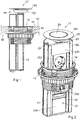
- Figure 1 shows a connection tower 11 that is mounted in a circular hole 12 in a preferably plane plate 13 having an outwardly/upwardly facing surface 14.
- a mounting ring 15 is attached that sealingly abuts against the outwardly/upwardly facing surface as well as against an inwardly/downwardly facing surface 16.
- the connection tower 11 is provided with a cover member 17 that comprises an elastic seal 18 placed in the cover member.
- the elastic seal comprises a peripherally situated ring-shaped cover part 181 and a centrally situated part 182.
- FIG. 2 shows in perspective the connection tower 11, which is mounted in rails and axially displaceable in an opening 19 in the mounting ring 15.
- the connection tower 11 is formed with an elongate mounting opening 21 hidden under a cover lid 231, which mounting opening is limited laterally by profile rails 22 formed to carry the cover lid 231, sockets for consumers such as mains voltage sockets 232, computer sockets 233 and telephone connections. All these sockets, plane or angled, and cover lids have the same connection against the profile rails in such a way that they can be displaced in the same and be placed in optional position along the mounting opening 21.
- the connection tower is partly projected but on the way to be pushed in, the surface of the entire cover member 17 being essentially plane.
- FIG. 2 shows furthermore that the cover member 17 centrally is provided with an operating member 24 in the form of a circularly formed button.
- an operating member 24 in the form of a circularly formed button.
- the ring-shaped cover part 181 is placed, which transforms into the centrally situated part 182.
- the cover member also comprises a fastening plate 25, which is mounted to the projecting end of the connection tower by screws 26.
- Figure 3 shows a section through the cover member 17 in a position wherein the schematically shown connection tower 11 is in an inserted position, the operating member 24 being arranged flush with the ring-shaped cover part 181 of the elastic seal 18.
- the cover part 181 also abuts against the schematically shown mounting ring 15 that is attached in the plane plate 13.
- the operating member 24 is formed with a surface 31 being plane or slightly bulging on the outside as well as is reinforced on the inside with a number of radially arranged wings 32.
- the operating member 24 is axially movable along an imaginary centre axis C and is arranged to, by a helical spring 34, actuate a spring housing 33 connected to the operating member to assume, upon a depression of the operating member from the position in the figure, the position shown in Figure 4 .
- the operating member 24 has, by force actuation, been displaced the distance "L", where 10 mm ⁇ L ⁇ 40 mm, outward from the ring-shaped cover part 181 and in this connection formed a handle to axially move the entire connection tower 11.
- the figure also shows that the centrally situated part 182 of the seal 18 extends in under the entire operating member 24 and is attached by a collar 41 to a circular fold 42 of the fastening plate 25.
- a spring seat 43 is connected by means of screws 36, said spring housing 33 being movable in the spring seat in such a way that a ratchet mechanism 44, 45, 46 of the operating member by axial displacement and turning, respectively, is actuated for retracted/extended position of the operating member.
- the ratchet mechanism reminds in its function of the ratchet mechanism in a conventional ballpoint pen.
- the handle formed of the operating member 24 can be gripped and the entire connection tower 11 be pulled out in relation to the mounting ring 15 from the surface 14 all the way to an end position, not shown, in which all connections mounted in the mounting opening 21 can be reached.
- the ring-shaped cover part 181 is elastic, the same can be bent away in such a way that connected electric cables and wires can pass between the mounting ring 15 and the deflected ring-shaped cover part 181.
- the deformation of the cover part 181 can be limited to a local area around the cables/wires while the remaining periphery of the cover part 181 remains sealingly against the mounting ring.
- it is easy to replace the entire seal by unscrewing the operating member 24 from the spring housing 33, loosen the spring seat with the ratchet mechanism from the fastening plate 25 and pull off the worn seal from the fold 42 and install a new seal.
Landscapes
- Engineering & Computer Science (AREA)
- Architecture (AREA)
- Civil Engineering (AREA)
- Structural Engineering (AREA)
- Connector Housings Or Holding Contact Members (AREA)
- Surgical Instruments (AREA)
- Measuring Or Testing Involving Enzymes Or Micro-Organisms (AREA)
- Materials For Medical Uses (AREA)
Claims (5)
- Tour de connexion (11) montée en surface, formée de manière déplaçable axialement dans une ouverture (19) dans une bague de montage (15) qui est connectée de manière fixe dans un trou (12) dans une plaque de préférence plane (13) ayant une surface tournée vers l'extérieur/vers le haut (14), la tour de connexion (11) pouvant être déplacée par rapport à la surface (14) de manière à se déplacer entre une position en saillie et une position insérée et la tour de connexion (11) étant pourvue de dispositifs de connexion électrique (232, 233) auxquels des câbles peuvent être connectés, un organe fonctionnel (24) étant monté sur l'extrémité pouvant être mise en saillie de la tour de connexion (11) et étant formé de manière à agir au moins en partie en tant que poignée fonctionnelle pour le déplacement de la tour de connexion (11), caractérisée en ce que l'organe fonctionnel (24), dans la position insérée de la tour de connexion (11), se raccorde à un joint élastique (18) formé avec une partie de recouvrement de forme annulaire (181) qui forme conjointement avec l'organe fonctionnel (24) un organe de recouvrement (17) qui recouvre l'ouverture et dont le bord extérieur est formé de manière à buter entièrement ou en partie de manière étanche contre la bague de montage (15), la partie de recouvrement le forme annulaire (181) étant élastique de manière à permettre le passage de câbles connectés de la tour de connexion (11) à travers la bague de montage (15) même lorsque la tour de connexion (11) est dans la position insérée.
- Tour de connexion selon la revendication 1, caractérisée en ce que l'organe fonctionnel (24) est placé centralement dans la partie de recouvrement de forme annulaire (181), l'organe fonctionnel (24) pouvant être déplacé en ligne droite dans la direction axiale par rapport à la tour de connexion (11) ainsi que par rapport à la partie de recouvrement de forme annulaire (181), un verrouillage de la tour de connexion (11) dans une position insérée et un déverrouillage de la tour de connexion (11) de ladite position, respectivement, étant prévus pour être effectués par le biais du mouvement dudit organe fonctionnel (24).
- Tour de connexion selon la revendication 2, caractérisée en ce que l'organe fonctionnel (24) adopte une position en saillie par rapport à la tour de connexion (11) après ledit déverrouillage de manière à former la poignée fonctionnelle.
- Tour de connexion selon l'une quelconque des revendications 1 à 3, caractérisée en ce que l'organe de recouvrement (17) et l'organe fonctionnel (24) forment une surface commune qui est soit plane soit légèrement convexe par rapport à la surface tournée vers l'extérieur/vers le haut (14).
- Tour de connexion selon l'une quelconque des revendications 1 à 4, caractérisée en ce que la surface tournée vers l'extérieur/vers le haut (14) est un dessus de table.
Applications Claiming Priority (1)
| Application Number | Priority Date | Filing Date | Title |
|---|---|---|---|
| SE0850155A SE533273C2 (sv) | 2008-12-19 | 2008-12-19 | Ytmonterat anslutningstorn |
Publications (2)
| Publication Number | Publication Date |
|---|---|
| EP2200128A1 EP2200128A1 (fr) | 2010-06-23 |
| EP2200128B1 true EP2200128B1 (fr) | 2016-01-27 |
Family
ID=41800699
Family Applications (1)
| Application Number | Title | Priority Date | Filing Date |
|---|---|---|---|
| EP09177260.8A Not-in-force EP2200128B1 (fr) | 2008-12-19 | 2009-11-26 | Tour de connexion assemblé en surface |
Country Status (4)
| Country | Link |
|---|---|
| EP (1) | EP2200128B1 (fr) |
| DK (1) | DK2200128T3 (fr) |
| ES (1) | ES2564832T3 (fr) |
| SE (1) | SE533273C2 (fr) |
Cited By (1)
| Publication number | Priority date | Publication date | Assignee | Title |
|---|---|---|---|---|
| EP4351917A4 (fr) * | 2020-06-09 | 2025-06-25 | Rodney Alexander Walker | Appareil et procédé pour charger des véhicules électriques |
Families Citing this family (5)
| Publication number | Priority date | Publication date | Assignee | Title |
|---|---|---|---|---|
| FR2965421B1 (fr) * | 2010-09-27 | 2012-09-28 | Legrand France | Accessoire electrique monte mobile en translation dans une ouverture pratiquee dans une paroi |
| FR2965420B1 (fr) * | 2010-09-27 | 2012-09-28 | Legrand France | Accessoire electrique monte mobile en translation dans une ouverture pratiquee dans une paroi |
| EP2811600A3 (fr) * | 2013-06-03 | 2015-09-02 | OE Electrics Limited | Appareil de connexion de puissance et/ou de données |
| EP2863502A1 (fr) * | 2013-10-14 | 2015-04-22 | Schulte Elektrotechnik GmbH & Co. Kg | Dispositif de raccordement d'appareils électriques |
| CN104659526B (zh) * | 2013-11-22 | 2019-04-19 | 肯迪特公司 | 用于在板上提供电连接和/或通信连接的装置 |
Family Cites Families (5)
| Publication number | Priority date | Publication date | Assignee | Title |
|---|---|---|---|---|
| US3646244A (en) * | 1970-08-21 | 1972-02-29 | Cole & Co Inc C W | Adjustable floor receptacle mount |
| US3794956A (en) * | 1972-06-30 | 1974-02-26 | R Dubreuil | Recessible electric floor or the like outlet assembly |
| WO2006034513A1 (fr) * | 2004-09-20 | 2006-03-30 | Raymond Mazzullo | Systeme d'alimentation electrique |
| US7163409B1 (en) * | 2006-07-19 | 2007-01-16 | Hoolin Research Company Limited | Modular integrated socket apparatus |
| DE102007051053A1 (de) * | 2006-10-19 | 2008-08-21 | Bachmann Gmbh & Co. Kg | Anschlusssäule als Einschubteil |
-
2008
- 2008-12-19 SE SE0850155A patent/SE533273C2/sv not_active IP Right Cessation
-
2009
- 2009-11-26 DK DK09177260.8T patent/DK2200128T3/en active
- 2009-11-26 EP EP09177260.8A patent/EP2200128B1/fr not_active Not-in-force
- 2009-11-26 ES ES09177260.8T patent/ES2564832T3/es active Active
Cited By (1)
| Publication number | Priority date | Publication date | Assignee | Title |
|---|---|---|---|---|
| EP4351917A4 (fr) * | 2020-06-09 | 2025-06-25 | Rodney Alexander Walker | Appareil et procédé pour charger des véhicules électriques |
Also Published As
| Publication number | Publication date |
|---|---|
| EP2200128A1 (fr) | 2010-06-23 |
| DK2200128T3 (en) | 2016-03-14 |
| SE0850155A1 (sv) | 2010-06-20 |
| ES2564832T3 (es) | 2016-03-29 |
| SE533273C2 (sv) | 2010-08-03 |
Similar Documents
| Publication | Publication Date | Title |
|---|---|---|
| EP2200128B1 (fr) | Tour de connexion assemblé en surface | |
| CN113508500B (zh) | 用于插座元件的安装元件 | |
| US7112097B1 (en) | Compact electrical power outlet system | |
| EP2806765B1 (fr) | Ensemble électrique à connecteur femelle à fermeture automatique et à profil réduit | |
| US7541540B1 (en) | Expandable in-use outlet cover | |
| CN100440641C (zh) | 具有插接附件的插头装置 | |
| US20150099402A1 (en) | Electrical plug | |
| EP2413437B1 (fr) | Fiche rotative et dispositif électronique doté d'une telle fiche rotative | |
| US20100248509A1 (en) | Plug with connecting device | |
| US8197273B1 (en) | German/French style plug with multiple pin arrangements | |
| US20120258632A1 (en) | Thin socket | |
| CN104459226B (zh) | 高压线路监测仪及其壳体 | |
| US20220109268A1 (en) | Receptacle Head for Power Extension Cord | |
| CN105552662A (zh) | 一种多功能插线板 | |
| WO2010127392A1 (fr) | Interrupteur de prise | |
| DK2164143T3 (en) | floor Box | |
| CN106921078B (zh) | 一种旋转式暗藏地插 | |
| EP2025993A3 (fr) | Douille de lampe à décharge | |
| CN201663423U (zh) | 一种线缆接线盒 | |
| KR20180002649U (ko) | 전기 콘센트의 판스프링 체결구조 | |
| MXPA06008346A (es) | Clavija coaxial. | |
| WO2010119406A1 (fr) | Systèmes d'alimentation électrique | |
| KR101925207B1 (ko) | 원터치형 콘센트 | |
| CN211150980U (zh) | 一种插座用面板安装结构及一种插座 | |
| CN210142749U (zh) | 一种可伸缩旋转的插头及插线板 |
Legal Events
| Date | Code | Title | Description |
|---|---|---|---|
| PUAI | Public reference made under article 153(3) epc to a published international application that has entered the european phase |
Free format text: ORIGINAL CODE: 0009012 |
|
| AK | Designated contracting states |
Kind code of ref document: A1 Designated state(s): AT BE BG CH CY CZ DE DK EE ES FI FR GB GR HR HU IE IS IT LI LT LU LV MC MK MT NL NO PL PT RO SE SI SK SM TR |
|
| AX | Request for extension of the european patent |
Extension state: AL BA RS |
|
| 17P | Request for examination filed |
Effective date: 20101015 |
|
| 17Q | First examination report despatched |
Effective date: 20141209 |
|
| GRAP | Despatch of communication of intention to grant a patent |
Free format text: ORIGINAL CODE: EPIDOSNIGR1 |
|
| INTG | Intention to grant announced |
Effective date: 20150518 |
|
| GRAS | Grant fee paid |
Free format text: ORIGINAL CODE: EPIDOSNIGR3 |
|
| GRAP | Despatch of communication of intention to grant a patent |
Free format text: ORIGINAL CODE: EPIDOSNIGR1 |
|
| INTG | Intention to grant announced |
Effective date: 20150924 |
|
| RIN1 | Information on inventor provided before grant (corrected) |
Inventor name: DAHL, STURE Inventor name: ERIKSSON, STAFFAN Inventor name: SUNDIN, LARS |
|
| GRAA | (expected) grant |
Free format text: ORIGINAL CODE: 0009210 |
|
| RAP1 | Party data changed (applicant data changed or rights of an application transferred) |
Owner name: SCHNEIDER ELECTRIC INDUSTRIES SAS |
|
| AK | Designated contracting states |
Kind code of ref document: B1 Designated state(s): AT BE BG CH CY CZ DE DK EE ES FI FR GB GR HR HU IE IS IT LI LT LU LV MC MK MT NL NO PL PT RO SE SI SK SM TR |
|
| REG | Reference to a national code |
Ref country code: GB Ref legal event code: FG4D |
|
| REG | Reference to a national code |
Ref country code: CH Ref legal event code: EP |
|
| REG | Reference to a national code |
Ref country code: AT Ref legal event code: REF Ref document number: 773097 Country of ref document: AT Kind code of ref document: T Effective date: 20160215 |
|
| REG | Reference to a national code |
Ref country code: IE Ref legal event code: FG4D |
|
| REG | Reference to a national code |
Ref country code: DE Ref legal event code: R096 Ref document number: 602009035966 Country of ref document: DE |
|
| REG | Reference to a national code |
Ref country code: DK Ref legal event code: T3 Effective date: 20160310 |
|
| REG | Reference to a national code |
Ref country code: ES Ref legal event code: FG2A Ref document number: 2564832 Country of ref document: ES Kind code of ref document: T3 Effective date: 20160329 |
|
| REG | Reference to a national code |
Ref country code: NO Ref legal event code: T2 Effective date: 20160127 |
|
| REG | Reference to a national code |
Ref country code: NL Ref legal event code: FP |
|
| REG | Reference to a national code |
Ref country code: SE Ref legal event code: TRGR |
|
| REG | Reference to a national code |
Ref country code: LT Ref legal event code: MG4D |
|
| REG | Reference to a national code |
Ref country code: AT Ref legal event code: MK05 Ref document number: 773097 Country of ref document: AT Kind code of ref document: T Effective date: 20160127 |
|
| PG25 | Lapsed in a contracting state [announced via postgrant information from national office to epo] |
Ref country code: HR Free format text: LAPSE BECAUSE OF FAILURE TO SUBMIT A TRANSLATION OF THE DESCRIPTION OR TO PAY THE FEE WITHIN THE PRESCRIBED TIME-LIMIT Effective date: 20160127 Ref country code: IT Free format text: LAPSE BECAUSE OF FAILURE TO SUBMIT A TRANSLATION OF THE DESCRIPTION OR TO PAY THE FEE WITHIN THE PRESCRIBED TIME-LIMIT Effective date: 20160127 Ref country code: GR Free format text: LAPSE BECAUSE OF FAILURE TO SUBMIT A TRANSLATION OF THE DESCRIPTION OR TO PAY THE FEE WITHIN THE PRESCRIBED TIME-LIMIT Effective date: 20160428 |
|
| PG25 | Lapsed in a contracting state [announced via postgrant information from national office to epo] |
Ref country code: IS Free format text: LAPSE BECAUSE OF FAILURE TO SUBMIT A TRANSLATION OF THE DESCRIPTION OR TO PAY THE FEE WITHIN THE PRESCRIBED TIME-LIMIT Effective date: 20160527 Ref country code: PL Free format text: LAPSE BECAUSE OF FAILURE TO SUBMIT A TRANSLATION OF THE DESCRIPTION OR TO PAY THE FEE WITHIN THE PRESCRIBED TIME-LIMIT Effective date: 20160127 Ref country code: LV Free format text: LAPSE BECAUSE OF FAILURE TO SUBMIT A TRANSLATION OF THE DESCRIPTION OR TO PAY THE FEE WITHIN THE PRESCRIBED TIME-LIMIT Effective date: 20160127 Ref country code: PT Free format text: LAPSE BECAUSE OF FAILURE TO SUBMIT A TRANSLATION OF THE DESCRIPTION OR TO PAY THE FEE WITHIN THE PRESCRIBED TIME-LIMIT Effective date: 20160527 Ref country code: AT Free format text: LAPSE BECAUSE OF FAILURE TO SUBMIT A TRANSLATION OF THE DESCRIPTION OR TO PAY THE FEE WITHIN THE PRESCRIBED TIME-LIMIT Effective date: 20160127 Ref country code: LT Free format text: LAPSE BECAUSE OF FAILURE TO SUBMIT A TRANSLATION OF THE DESCRIPTION OR TO PAY THE FEE WITHIN THE PRESCRIBED TIME-LIMIT Effective date: 20160127 |
|
| REG | Reference to a national code |
Ref country code: DE Ref legal event code: R097 Ref document number: 602009035966 Country of ref document: DE |
|
| PG25 | Lapsed in a contracting state [announced via postgrant information from national office to epo] |
Ref country code: EE Free format text: LAPSE BECAUSE OF FAILURE TO SUBMIT A TRANSLATION OF THE DESCRIPTION OR TO PAY THE FEE WITHIN THE PRESCRIBED TIME-LIMIT Effective date: 20160127 |
|
| REG | Reference to a national code |
Ref country code: FR Ref legal event code: PLFP Year of fee payment: 8 |
|
| PG25 | Lapsed in a contracting state [announced via postgrant information from national office to epo] |
Ref country code: RO Free format text: LAPSE BECAUSE OF FAILURE TO SUBMIT A TRANSLATION OF THE DESCRIPTION OR TO PAY THE FEE WITHIN THE PRESCRIBED TIME-LIMIT Effective date: 20160127 Ref country code: SK Free format text: LAPSE BECAUSE OF FAILURE TO SUBMIT A TRANSLATION OF THE DESCRIPTION OR TO PAY THE FEE WITHIN THE PRESCRIBED TIME-LIMIT Effective date: 20160127 Ref country code: CZ Free format text: LAPSE BECAUSE OF FAILURE TO SUBMIT A TRANSLATION OF THE DESCRIPTION OR TO PAY THE FEE WITHIN THE PRESCRIBED TIME-LIMIT Effective date: 20160127 Ref country code: SM Free format text: LAPSE BECAUSE OF FAILURE TO SUBMIT A TRANSLATION OF THE DESCRIPTION OR TO PAY THE FEE WITHIN THE PRESCRIBED TIME-LIMIT Effective date: 20160127 |
|
| PLBE | No opposition filed within time limit |
Free format text: ORIGINAL CODE: 0009261 |
|
| STAA | Information on the status of an ep patent application or granted ep patent |
Free format text: STATUS: NO OPPOSITION FILED WITHIN TIME LIMIT |
|
| PG25 | Lapsed in a contracting state [announced via postgrant information from national office to epo] |
Ref country code: BE Free format text: LAPSE BECAUSE OF FAILURE TO SUBMIT A TRANSLATION OF THE DESCRIPTION OR TO PAY THE FEE WITHIN THE PRESCRIBED TIME-LIMIT Effective date: 20160127 |
|
| 26N | No opposition filed |
Effective date: 20161028 |
|
| PG25 | Lapsed in a contracting state [announced via postgrant information from national office to epo] |
Ref country code: SI Free format text: LAPSE BECAUSE OF FAILURE TO SUBMIT A TRANSLATION OF THE DESCRIPTION OR TO PAY THE FEE WITHIN THE PRESCRIBED TIME-LIMIT Effective date: 20160127 Ref country code: BG Free format text: LAPSE BECAUSE OF FAILURE TO SUBMIT A TRANSLATION OF THE DESCRIPTION OR TO PAY THE FEE WITHIN THE PRESCRIBED TIME-LIMIT Effective date: 20160427 |
|
| REG | Reference to a national code |
Ref country code: DE Ref legal event code: R119 Ref document number: 602009035966 Country of ref document: DE |
|
| REG | Reference to a national code |
Ref country code: CH Ref legal event code: PL |
|
| GBPC | Gb: european patent ceased through non-payment of renewal fee |
Effective date: 20161126 |
|
| PG25 | Lapsed in a contracting state [announced via postgrant information from national office to epo] |
Ref country code: LI Free format text: LAPSE BECAUSE OF NON-PAYMENT OF DUE FEES Effective date: 20161130 Ref country code: CH Free format text: LAPSE BECAUSE OF NON-PAYMENT OF DUE FEES Effective date: 20161130 |
|
| REG | Reference to a national code |
Ref country code: IE Ref legal event code: MM4A |
|
| PG25 | Lapsed in a contracting state [announced via postgrant information from national office to epo] |
Ref country code: LU Free format text: LAPSE BECAUSE OF NON-PAYMENT OF DUE FEES Effective date: 20161130 |
|
| REG | Reference to a national code |
Ref country code: FR Ref legal event code: PLFP Year of fee payment: 9 |
|
| PG25 | Lapsed in a contracting state [announced via postgrant information from national office to epo] |
Ref country code: IE Free format text: LAPSE BECAUSE OF NON-PAYMENT OF DUE FEES Effective date: 20161126 Ref country code: DE Free format text: LAPSE BECAUSE OF NON-PAYMENT OF DUE FEES Effective date: 20170601 Ref country code: GB Free format text: LAPSE BECAUSE OF NON-PAYMENT OF DUE FEES Effective date: 20161126 |
|
| PG25 | Lapsed in a contracting state [announced via postgrant information from national office to epo] |
Ref country code: CY Free format text: LAPSE BECAUSE OF FAILURE TO SUBMIT A TRANSLATION OF THE DESCRIPTION OR TO PAY THE FEE WITHIN THE PRESCRIBED TIME-LIMIT Effective date: 20160127 Ref country code: HU Free format text: LAPSE BECAUSE OF FAILURE TO SUBMIT A TRANSLATION OF THE DESCRIPTION OR TO PAY THE FEE WITHIN THE PRESCRIBED TIME-LIMIT; INVALID AB INITIO Effective date: 20091126 |
|
| PG25 | Lapsed in a contracting state [announced via postgrant information from national office to epo] |
Ref country code: TR Free format text: LAPSE BECAUSE OF FAILURE TO SUBMIT A TRANSLATION OF THE DESCRIPTION OR TO PAY THE FEE WITHIN THE PRESCRIBED TIME-LIMIT Effective date: 20160127 Ref country code: MC Free format text: LAPSE BECAUSE OF FAILURE TO SUBMIT A TRANSLATION OF THE DESCRIPTION OR TO PAY THE FEE WITHIN THE PRESCRIBED TIME-LIMIT Effective date: 20160127 Ref country code: MK Free format text: LAPSE BECAUSE OF FAILURE TO SUBMIT A TRANSLATION OF THE DESCRIPTION OR TO PAY THE FEE WITHIN THE PRESCRIBED TIME-LIMIT Effective date: 20160127 |
|
| PG25 | Lapsed in a contracting state [announced via postgrant information from national office to epo] |
Ref country code: MT Free format text: LAPSE BECAUSE OF NON-PAYMENT OF DUE FEES Effective date: 20161126 |
|
| PGFP | Annual fee paid to national office [announced via postgrant information from national office to epo] |
Ref country code: FI Payment date: 20191119 Year of fee payment: 11 Ref country code: SE Payment date: 20191118 Year of fee payment: 11 Ref country code: NL Payment date: 20191118 Year of fee payment: 11 Ref country code: NO Payment date: 20191118 Year of fee payment: 11 |
|
| PGFP | Annual fee paid to national office [announced via postgrant information from national office to epo] |
Ref country code: FR Payment date: 20191115 Year of fee payment: 11 Ref country code: ES Payment date: 20191205 Year of fee payment: 11 Ref country code: DK Payment date: 20191118 Year of fee payment: 11 |
|
| REG | Reference to a national code |
Ref country code: FI Ref legal event code: MAE |
|
| REG | Reference to a national code |
Ref country code: NO Ref legal event code: MMEP Ref country code: DK Ref legal event code: EBP Effective date: 20201130 |
|
| REG | Reference to a national code |
Ref country code: SE Ref legal event code: EUG |
|
| REG | Reference to a national code |
Ref country code: NL Ref legal event code: MM Effective date: 20201201 |
|
| PG25 | Lapsed in a contracting state [announced via postgrant information from national office to epo] |
Ref country code: FI Free format text: LAPSE BECAUSE OF NON-PAYMENT OF DUE FEES Effective date: 20201126 Ref country code: NO Free format text: LAPSE BECAUSE OF NON-PAYMENT OF DUE FEES Effective date: 20201130 |
|
| PG25 | Lapsed in a contracting state [announced via postgrant information from national office to epo] |
Ref country code: NL Free format text: LAPSE BECAUSE OF NON-PAYMENT OF DUE FEES Effective date: 20201201 Ref country code: SE Free format text: LAPSE BECAUSE OF NON-PAYMENT OF DUE FEES Effective date: 20201127 |
|
| PG25 | Lapsed in a contracting state [announced via postgrant information from national office to epo] |
Ref country code: FR Free format text: LAPSE BECAUSE OF NON-PAYMENT OF DUE FEES Effective date: 20201130 |
|
| PG25 | Lapsed in a contracting state [announced via postgrant information from national office to epo] |
Ref country code: DK Free format text: LAPSE BECAUSE OF NON-PAYMENT OF DUE FEES Effective date: 20201130 |
|
| REG | Reference to a national code |
Ref country code: ES Ref legal event code: FD2A Effective date: 20220203 |
|
| PG25 | Lapsed in a contracting state [announced via postgrant information from national office to epo] |
Ref country code: ES Free format text: LAPSE BECAUSE OF NON-PAYMENT OF DUE FEES Effective date: 20201127 |