EP2200138A2 - Elektro-Installationsgerät mit Trägerrahmen und Bedien- oder Funktionselement - Google Patents
Elektro-Installationsgerät mit Trägerrahmen und Bedien- oder Funktionselement Download PDFInfo
- Publication number
- EP2200138A2 EP2200138A2 EP09014322A EP09014322A EP2200138A2 EP 2200138 A2 EP2200138 A2 EP 2200138A2 EP 09014322 A EP09014322 A EP 09014322A EP 09014322 A EP09014322 A EP 09014322A EP 2200138 A2 EP2200138 A2 EP 2200138A2
- Authority
- EP
- European Patent Office
- Prior art keywords
- support frame
- functional element
- operating
- removal protection
- frame
- Prior art date
- Legal status (The legal status is an assumption and is not a legal conclusion. Google has not performed a legal analysis and makes no representation as to the accuracy of the status listed.)
- Granted
Links
Images


Classifications
-
- H—ELECTRICITY
- H02—GENERATION; CONVERSION OR DISTRIBUTION OF ELECTRIC POWER
- H02G—INSTALLATION OF ELECTRIC CABLES OR LINES, OR OF COMBINED OPTICAL AND ELECTRIC CABLES OR LINES
- H02G3/00—Installations of electric cables or lines or protective tubing therefor in or on buildings, equivalent structures or vehicles
- H02G3/02—Details
- H02G3/08—Distribution boxes; Connection or junction boxes
- H02G3/12—Distribution boxes; Connection or junction boxes for flush mounting
-
- H—ELECTRICITY
- H02—GENERATION; CONVERSION OR DISTRIBUTION OF ELECTRIC POWER
- H02G—INSTALLATION OF ELECTRIC CABLES OR LINES, OR OF COMBINED OPTICAL AND ELECTRIC CABLES OR LINES
- H02G3/00—Installations of electric cables or lines or protective tubing therefor in or on buildings, equivalent structures or vehicles
- H02G3/02—Details
- H02G3/08—Distribution boxes; Connection or junction boxes
- H02G3/086—Assembled boxes
Definitions
- the invention relates to an electrical installation device with a base unit which can be mounted in a standard flush-mounted box, which can be latched via at least one support frame with at least one operating or functional element, including the at least one operating or functional element by means of a latching hook arranged at one end of a spring leg Support frame recess in the support frame is in engagement with a latching surface.
- a sensor unit with a standard standard flush-mounted mountable base unit is known, which is connectable to at least one control or functional element, wherein a base support is provided which has at least one field including an inserted support frame for receiving an operating or functional element, wherein in the base support several electrically conductive rails are integrated, which partially serve for the electrical power supply and partly for communication.
- the assembly of an operating or functional element on a support frame of the sensor unit is preferably carried out via a latch. It should be possible on the one hand in the course of the first installation of an operating or functional element on the support frame disassembly of an operating or functional element of the support frame to make such settings / correct to can, on the other hand, however, an unauthorized driving a control element "in passing" during the subsequent normal operation can be prevented.
- the invention has for its object to provide an electrical installation device of the type mentioned with optimized locking between an operating or functional element and a support frame.
- a removal protection is provided, which is mountable via connecting means at the location of the support frame recess on the support frame and which has a frame and an attached thereto, immersed in the support frame recess support plate which impedes a deflection of the spring leg of the operating or functional element.
- the advantages that can be achieved with the invention are, in particular, that virtually verification of a two-stage latching between an operating or functional element and a carrier frame is verified by non-assembly / assembly (non-incipient splicing / clipping) of a removal guard.
- non-assembly / assembly non-incipient splicing / clipping
- the removal protection in the first Verrastungscut - non-clipping the removal protection - as often disassembly of an operating or functional element of the support frame with usual, relatively low force (withdrawal force) done by the operating or functional element taken at the edges of his front panel in the hand and is subtracted from the support frame.
- the installer can make settings on the base unit with disassembled operating or functional element, then tested with mounted operating or functional element and optionally modified with disassembled control or functional element.
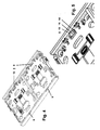
- Fig. 1 is a section through an electrical installation device, in particular a sensor unit (Tastsensormaschine) shown.
- the electrical installation device 1 has a support frame 8, on which at least one control or functional element 2 or 3 is fixed, for example, a rotary-push element with a knob, a rotary element, a single button, a multi-button (such as two-button or triple button), a display (display element), a touch screen, a motion detector or a communication element (such as a speaker or microphone).
- the support frame 8 has the function of a connecting element between a mounted in a standard flush-mounted device box base unit and the individual control or functional elements.
- the attachment between control or functional element 2 or 3 and the support frame 8 is effected by a latching, to which the operating or functional elements 2 or 3 are each provided with at least one latching hook 4, which is arranged at the free end of a spring leg 5.
- the support frame 8 at least one support frame recess 9 for the engagement of the latching hook 4.
- a side wall of this support frame recess 9 has a special design with a sliding surface 10 and a subsequent latching surface 11.
- a removal protection 13 plays an essential role as an additional separate component. This can be inserted into the carrier frame recess 9 and locked there removal removal 13 is in the following FIGS. 2 and 3 shown in detail, in the sectional view according to Fig. 1 are only a frame 14 and a molded-on support plate 22 of the removal protection 13 can be seen, wherein the frame 14 encloses a removal protection recess 15 of the removal protection 13. For easier insertion of the latching hook 4 in the removal protection recess 15, the latter has an insertion bevel 16 on an inner edge of the frame 14.
- the frame 14 has a chamfer 17 on a (in the mounted state) the outer edge facing the support frame 8.
- the removal protection 13 can be levered from the support frame 8.
- the removal protection 13 can also be expressed from the rear side of the support frame 8.
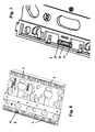
- FIG. 2 is a perspective view of the top of a removal protection shown.
- the top of the removal protection 13 is facing the operating or functional element 2 or 3 after installation on the support frame 8.
- the frame 14 of the removal protection 13 made of a plastic allows the integral molding of the support plate 22 and two spring legs 19 and 21 with latching hooks 18 and 20 at the end.
- the insertion bevel 16 is the insertion bevel 16 for facilitated insertion of the latching hook 4 in the frame 14 enclosed removal protection recess 15th
- FIG. 3 is a perspective view of the bottom of a removal protection shown.
- the two spring hooks 19 and 21 connected to the frame 14 latching hooks 18 and 20, the support plate 22 and the removal protection recess 15 can be seen.
- the chamfer 17 provided on an outer edge of the frame 14 is shown (which possibly facilitates a levering of the removal guard 13 from the carrier frame 8).
- FIG. 4 is a perspective view of the top of a support frame shown.
- the support frame 8 shown is suitable for receiving two operating or functional elements 2 or 3, wherein each of the operating or functional elements has two latching hooks 4, which engage in two mutually opposite support frame recesses 9 of the support frame 8.
- One of the support frame recesses 9 is exemplarily equipped with a removal guard 13.
- support frames can also be used for only a single operating or functional element or for three, four etc. operating or functional elements be realized.
- Fig. 5 is a detail view too Fig. 4 shown so as to show the position of an inserted into a support frame recess 9 of the support frame 8 removal protection 13 with frame 14 and insertion 16.
- FIG. 6 is a perspective view of the underside of a support frame shown.
- the carrier frame 8 shown is suitable for receiving two operating or functional elements 2 or 3, wherein each of the operating or functional elements has two latching hooks 4, which engage in two mutually opposite recesses 9 of the support frame 8.
- One of the recesses 9 is exemplified with a removal protection 13 equipped.
- FIG. 7 and 8th are two detailed views too Fig. 6 shown, wherein in both views a removal protection 13 is inserted into a support frame recess 9.
- the fixing of the removal protection 13 on the support frame 8 is carried out by the removal protection is inserted into the support frame recess 9 until the two latching hooks 18, 20 engage over the underside of the support frame 8, while the frame 14 presses against the top of the support frame 8.
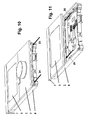
- Fig. 9 is shown in the form of a sensor unit designed electrical installation device.
- the electrical installation device 1 shown has, for example, two operating or functional elements 2, 3, wherein the operating or functional element 2 is designed as a rotary-pressing element with a rotary knob and the operating or functional element 3 as a display.
- the operating or functional element 2 is designed as a rotary-pressing element with a rotary knob and the operating or functional element 3 as a display.
- a respective end element 6 or 7 is arranged and locked on the support frame 8.
- the corresponding base unit suitable for installation in a commercially available flush-mounted box according to DIN 49073 is not shown.
- an operating or functional element 2 or 3 is to be detached from the carrier frame 8 when the electrical installation device 1 is mounted and the removal protection 13 is mounted (present the second locking step), then in a first step it is first necessary to disassemble the final element 6. Thereafter, in a second step, a tool (blade of a screwdriver) at the two corners 23, 24 of the operating or functional element 2 between the control or functional element 2 and the support frame 8 is inserted to such a levering off the control or functional element 2 of Carrier frame 8 to effect - see Fig.
- a tool blade of a screwdriver
- the tool is introduced in a third step at the two corners 25 and 26 of the control or functional element 3 between the control or functional element 3 and the support frame 8, to such a levering of the operating or functional element 3 from the support frame 8 to effect - see Fig. 11 ,
- a similar procedure is alternatively possible by first the end element 7 is withdrawn. Subsequently, the removal protection 13 can be levered off the support frame 8 or pushed out of the support frame recess 9.
Landscapes
- Engineering & Computer Science (AREA)
- Architecture (AREA)
- Civil Engineering (AREA)
- Structural Engineering (AREA)
- Casings For Electric Apparatus (AREA)
- Switch Cases, Indication, And Locking (AREA)
Abstract
Description
- Die Erfindung betrifft ein Elektro-Installationsgerät mit einem in einer handelsüblichen UP-Gerätedose montierbaren Basisgerät, welches über mindestens einen Trägerrahmen mit mindestens einem Bedien- oder Funktionselement verrastbar ist, wozu das mindestens eine Bedien- oder Funktionselement mittels eines endseitig eines Federschenkels angeordneten Rasthakens durch eine Trägerrahmen-Ausnehmung im Trägerrahmen in Eingriff mit einer Rastfläche steht.
- Aus der
EP 1 993 180 A2 ist eine Sensoreinheit mit einem in einer handelsüblichen Standard-Unterputzdose montierbaren Basisgerät bekannt, welches mit mindestens einem Bedien- oder Funktionselement verbindbar ist, wobei ein Grundträger vorgesehen ist, der mindestens ein Feld inklusive eines eingebrachten Tragrahmens zur Aufnahme eines Bedien- oder Funktionselementes aufweist, wobei im Grundträger mehrere elektrisch leitende Schienen integriert sind, welche teilweise für die elektrische Energieversorgung und teilweise für die Kommunikation dienen. - Die Montage eines Bedien- oder Funktionselementes auf einem Trägerrahmen der Sensoreinheit erfolgt vorzugsweise über eine Verrastung. Dabei soll einerseits im Zuge der erstmaligen Montage eines Bedien- oder Funktionselementes auf dem Trägerrahmen eine Demontage eines Bedien- oder Funktionselementes vom Trägerrahmen möglich sein, um derart Einstellungen vornehmen/korrigieren zu können, andererseits soll jedoch ein unbefugtes Mitnehmen eines Bedienelementes "im Vorbeigehen" während des späteren Normalbetriebes verhindert werden.
- Der Erfindung liegt die Aufgabe zugrunde, ein Elektro-Installationsgerät der eingangs genannten Art mit optimierter Verrastung zwischen einem Bedien- oder Funktionselement und einem Trägerrahmen anzugeben.
- Diese Aufgabe wird in Verbindung mit den Merkmalen des Oberbegriffes erfindungsgemäß dadurch gelöst, dass ein Entnahmeschutz vorgesehen ist, welcher über Verbindungsmittel am Ort der Trägerrahmen-Ausnehmung am Trägerrahmen montierbar ist und welcher einen Rahmen und eine daran befestigte, in die Trägerrahmen-Ausnehmung eintauchende Stützplatte aufweist, welche eine Auslenkung des Federschenkels des Bedien- oder Funktionselements erschwert.
- Die mit der Erfindung erzielbaren Vorteile liegen insbesondere darin, dass durch Nicht-Montage / Montage (Nicht-Einktipsen / Einklipsen) eines Entnahmeschutzes quasi eine zweistufige Verrastung zwischen einem Bedien- oder Funktionselement und einem Trägerrahmen verifiziert wird. Bei der ersten Verrastungsstufe - Nicht-Einklipsen des Entnahmeschutzes - kann beliebig oft die Demontage eines Bedien- oder Funktionselementes vom Trägerrahmen mit üblicher, relativ geringer Kraftaufwendung (Abzugskraft) erfolgen, indem das Bedien- oder Funktionselement an den Kanten seiner Frontplatte in die Hand genommen und vom Trägerrahmen abgezogen wird. Derart können durch den Installateur Einstellungen am Basisgerät bei demontiertem Bedien- oder Funktionselement vorgenommen, anschließend bei montiertem Bedien- oder Funktionselement getestet und gegebenenfalls bei demontiertem Bedien- oder Funktionselement geändert werden. Wenn alle Einstellungen in gewünschter Weise und mit zufriedenstellendem Ergebnis vorgenommen worden sind, werden zunächst der Entnahmeschutz und anschließend das Bedien- oder Funktionselement montiert. Danach ergibt sich eine wesentliche Erhöhung der zum Lösen erforderlichen Abzugskraft und somit eine Sicherung gegen ungewollte und unbefugte Entnahme. Ein Abziehen des Bedien- oder Funktionselementes vom Trägerrahmen per Hand ist nicht mehr möglich. Ein Mitnehmen des Bedien- oder Funktionselementes "im Vorbeigehen" durch unbefugte Personen wird verhindert. Dabei ist Montage des Entnahmeschutzes am Trägerrahmen durch Einklipsen/Verrasten sehr leicht möglich. Ferner ist auch eine Demontage des Entnahmeschutzes vom Trägerrahmen zu einem späteren Zeitpunkt möglich, wozu allerdings ein Werkzeug erforderlich ist, was wie gewünscht eine Demontage durch unbefugte Personen unterbindet oder zumindest wesentlich erschwert.
- Vorteilhafte Ausgestaltungen der Erfindung sind in den Unteransprüchen gekennzeichnet.
- Die Erfindung wird nachstehend an Hand der in der Zeichnung dargestellten Ausführungsbeispiele näher erläutert. Es zeigen:
- Fig. 1
- einen Schnitt durch ein Elektro-Installationsgerät,
- Fig. 2
- eine perspektivische Sicht auf die Oberseite eines Entnahmeschutzes,
- Fig. 3
- eine perspektivische Sicht auf die Unterseite eines Entnahmeschutzes,
- Fig. 4
- eine perspektivische Sicht auf die Oberseite eines Trägerrahmens,
- Fig. 5
- eine Detailansicht zu
Fig. 4 , - Fig. 6
- eine perspektivische Sicht auf die Unterseite eines Trägerrahmens,
- Fig. 7, 8
- zwei Detailansichten zu
Fig. 6 , - Fig. 9
- ein in Form einer Sensoreinheit ausgebildetes Elektro-Installationsgerät,
- Fig. 10, 11
- schematische Skizzen zur Erläuterung der Demontage eines Elektro-Installationsgeräts bei montiertem Entnahmeschutz.
- In
Fig. 1 ist ein Schnitt durch ein Elektro-Installationsgerät, insbesondere eine Sensoreinheit (Tastsensoreinheit), dargestellt. Das Elektro-Installationsgerät 1 weist einen Trägerrahmen 8 auf, auf welchem mindestens ein Bedien- oder Funktionselement 2 oder 3 befestigt ist, beispielsweise ein Dreh-Drückelement mit Drehknopf, ein Drehelement, ein Einfach-Taster, ein Mehrfach-Taster (wie Zweifach-Taster oder Dreifach-Taster), ein Display (Anzeigeelement), ein Touchscreen, ein Bewegungsmelder oder ein Kommunikationselement (wie Lautsprecher oder Mikrofon). Der Trägerrahmen 8 hat die Funktion eines Verbindungselementes zwischen einem in einer handelsüblichen UP-Gerätedose montiertem Basisgerät und den einzelnen Bedien- oder Funktionselementen. - Die Befestigung zwischen Bedien- oder Funktionselement 2 oder 3 und dem Trägerrahmen 8 erfolgt durch eine Verrastung, wozu die Bedien- oder Funktionselemente 2 oder 3 jeweils mit mindestens einem Rasthaken 4 versehen sind, welcher am freien Ende eines Federschenkels 5 angeordnet ist. Korrespondierend hierzu weist der Trägerrahmen 8 mindestens eine Trägerrahmen-Ausnehmung 9 für den Eingriff des Rasthakens 4 auf. Eine Seitenwand dieser Trägerrahmen-Ausnehmung 9 weist eine spezielle Ausgestaltung mit einer Gleitfläche 10 und einer sich anschließenden Rastfläche 11 auf. Beim Einführen des Rasthakens 4 in die Trägerrahmen-Ausnehmung 9 gleitet der Rasthaken 4 zunächst entlang der Gleitfläche 10 unter gleichzeitiger Auslenkung des Federschenkels 5 in x-Richtung. Nachdem der Rasthaken 4 die durch Gleitfläche 10 und Rastfläche 11 gebildete gemeinsame Kante erreicht hat, federt der Federschenkel 5 mit dem Rasthaken 4 zurück und der Rasthaken 4 greift unter die Rastfläche 11, wodurch die gewünschte Befestigung erzielt wird.
- Bei der Befestigung zwischen einem Bedien- oder Funktionselement 2 oder 3 und dem Trägerrahmen 8 spielt ein Entnahmeschutz 13 als zusätzliche separate Baukomponente eine wesentliche Rolle. Dieser in die Trägerrahmen-Ausnehmung 9 einführbare und dort verrastbare Entnahmeschutz 13 ist in den nachfolgenden
Figuren 2 und 3 detailliert dargestellt, in der Schnitt-Darstellung gemäßFig. 1 sind lediglich ein Rahmen 14 sowie eine daran angeformte Stützplatte 22 des Entnahmeschutzes 13 zu erkennen, wobei der Rahmen 14 eine Entnahmeschutz-Ausnehmung 15 des Entnahmeschutzes 13 umschließt. Zum erleichterten Einführen des Rasthakens 4 in die Entnahmeschutz-Ausnehmung 15 weist letztere eine Einführschräge 16 an einer Innenkante des Rahmens 14 auf. Um einen am Trägerahmen 8 montierten Entnahmeschutz 13 in einfacher Weise demontieren zu können, weist der Rahmen 14 an einer (bei montiertem Zustand) dem Trägerrahmen 8 zugewandten Außenkante eine Abschrägung 17 auf. Durch Einführen eines Werkzeuges zwischen Abschrägung 17 und Trägerrahmen 8, beispielsweise der Klinge eines Schraubendrehers, lässt sich der Entnahmeschutz 13 vom Trägerrahmen 8 abhebeln. Alternativ lässt sich der Entnahmeschutz 13 auch von der Rückseite des Trägerrahmens 8 her ausdrücken. - Wie bereits aus
Fig. 1 hervorgeht, ist eine zweistufige Verrastung zwischen einem Bedien- oder Funktionselement 2 oder 3 und dem Trägerrahmen 8 realisierbar: - Bei der ersten Verrastungsstufe ist der Entnahmeschutz 13 nicht in die Trägerrahmen-Ausnehmung 9 des Trägerrahmens 8 eingebracht. Es sei angenommen, der Rasthaken 4 greife unter die Rastfläche 11, so dass sich eine Befestigung des Bedien- oder Funktionselementes 2 oder 3 am Trägerrahmen 8 ergibt. Sobald am Bedien- oder Funktionselement 2 oder 3 per Hand in y-Richtung gezogen wird, löst sich nach Überschreiten einer vorgebbaren Kraft (Abzugskraft) die Verrastung zwischen Rasthaken 4 und Rastfläche 11 unter gleichzeitiger Auslenkung des Federschenkels 5 in x-Richtung. Das Bedien- oder Funktionselement 2 oder 3 lässt sich per Hand vom Trägerrahmen 8 lösen.
- Bei der zweiten Verrastungsstufe ist der Entnahmeschutz 13 in die Trägerrahmen-Ausnehmung 9 des Trägerrahmens 8 eingebracht. Beim Einführen des Rasthakens 4 in die Entnahmeschutz-Ausnehmung 15 und anschließenden Druck auf das Bedien- oder Funktionselement (entgegen der y-Richtung) ergibt sich zunächst eine geringe Auslenkung der Stützplatte 22 in x-Richtung, bis der Rasthaken am Ort der Rastfläche 11 verrastet. Es sei angenommen, der Rasthaken 4 greife unter die Rastfläche 11, so dass sich eine Befestigung des Bedien- oder Funktionselementes 2 oder 3 am Trägerrahmen 8 ergibt. Sobald am Bedien- oder Funktionselement 2 oder 3 per Hand in y-Richtung gezogen wird, entsteht - bedingt durch die Schrägflächen der Rastfläche 11 und des Rasthakens 4 - eine Kraftkomponente in x-Richtung, welche versucht, den Rasthaken in x-Richtung auszulenken. Der Rasthaken 4 mit Federschenkel 5 presst somit gegen die Stützplatte 22 des Entnahmeschutzes 13. Die Stützplatte 22 verhindert aufgrund ihrer relativ hohen Steifigkeit eine nennenswerte Auslenkung des Federschenkels 5 in x-Richtung. Folglich wird der Rasthaken 4 des Bedien- oder Funktionselementes im eingerasteten Zustand blockiert. Das Bedien- oder Funktionselement 2 oder 3 lässt sich nicht mehr per Hand vom Trägerrahmen 8 lösen.
- In
Fig. 2 ist eine perspektivische Sicht auf die Oberseite eines Entnahmeschutzes dargestellt. Die Oberseite des Entnahmeschutzes 13 ist nach erfolgter Montage am Trägerrahmen 8 dem Bedien- oder Funktionselement 2 oder 3 zugewandt. Wie zu erkennen ist, ermöglicht der Rahmen 14 des aus einem Kunststoff bestehenden Entnahmeschutzes 13 die einstückige Anformung der Stützplatte 22 sowie zweier Federschenkel 19 bzw. 21 mit endseitig daran befindlichen Rasthaken 18 bzw. 20. An der Oberseite der Stützplatte 22 respektive der zugehörigen Innenkante des Rahmens 14 befindet sich die Einführschräge 16 für das erleichterte Einführen des Rasthakens 4 in die vom Rahmen 14 umschlossene Entnahmeschutz-Ausnehmung 15. - In
Fig. 3 ist eine perspektivische Sicht auf die Unterseite eines Entnahmeschutzes dargestellt. Es sind wiederum die beiden über Federschenkel 19 bzw. 21 mit dem Rahmen 14 verbundenen Rasthaken 18 bzw. 20, die Stützplatte 22 sowie die Entnahmeschutz-Ausnehmung 15 zu erkennen. Des Weiteren ist die an einer Außenkante des Rahmens 14 vorgesehene Abschrägung 17 dargestellt (welche ggf. ein Abhebeln des Entnahmeschutzes 13 vom Trägerrahmen 8 erleichtert). - In
Fig. 4 ist eine perspektivische Sicht auf die Oberseite eines Trägerrahmens dargestellt. Der gezeigte Trägerrahmen 8 ist zur Aufnahme von zwei Bedien- oder Funktionselementen 2 oder 3 geeignet, wobei jedes der Bedien- oder Funktionselemente zwei Rasthaken 4 aufweist, welche in je zwei sich gegenüberliegende Trägerrahmen-Ausnehmungen 9 des Trägerrahmens 8 eingreifen. Eine der Trägerrahmen-Ausnehmungen 9 ist beispielhaft mit einem Entnahmeschutz 13 bestückt. Selbstverständlich können abweichend hiervon auch Trägerrahmen für lediglich ein einziges Bedien- oder Funktionselement oder für drei, vier usw. Bedien- oder Funktionselemente realisiert sein. Des Weiteren ist es selbstverständlich auch möglich, je Bedien- oder Funktionselement lediglich einen einzigen Rasthaken oder drei, vier usw. Rasthaken vorzusehen. - In
Fig. 5 ist eine Detailansicht zuFig. 4 dargestellt, um derart die Lage eines in eine Trägerrahmen-Ausnehmung 9 des Trägerrahmens 8 eingesteckten Entnahmeschutzes 13 mit Rahmen 14 und Einführschräge 16 zu zeigen. - In
Fig. 6 ist eine perspektivische Sicht auf die Unterseite eines Trägerrahmens dargestellt. Der gezeigte Trägerrahmen 8 ist zur Aufnahme von zwei Bedien- oder Funktionselementen 2 oder 3 geeignet, wobei jedes der Bedien- oder Funktionselemente zwei Rasthaken 4 aufweist, welche in je zwei sich gegenüberliegende Ausnehmungen 9 des Trägerrahmens 8 eingreifen. Eine der Ausnehmungen 9 ist beispielhaft mit einem Entnahmeschutz 13 bestückt. - In den
Fig. 7 und8 sind zwei Detailansichten zuFig. 6 dargestellt, wobei bei beiden Ansichten ein Entnahmeschutz 13 in eine Trägerrahmen-Ausnehmung 9 eingesteckt ist. Die Fixierung des Entnahmeschutzes 13 am Trägerrahmen 8 erfolgt, indem der Entnahmeschutz in die Trägerrahmen-Ausnehmung 9 eingesteckt wird, bis die beiden Rasthaken 18, 20 über die Unterseite des Trägerrahmens 8 greifen, während gleichzeitig der Rahmen 14 gegen die Oberseite des Trägerahmens 8 drückt. Bei der Darstellung gemäßFig. 8 ist zusätzlich ein durch die Entnahmeschutz-Ausnehmung 15 des Entnahmeschutzes 13 greifender und an der Rastfläche 11 des Trägerrahmens 8 verrasteter Rasthaken 4 eines Bedien- oder Funktionselementes zu erkennen. - In
Fig. 9 ist ein in Form einer Sensoreinheit ausgebildetes Elektro-Installationsgerät dargestellt. Das gezeigte Elektro-Installationsgerät 1 besitzt beispielsweise zwei Bedien- oder Funktionselemente 2, 3, wobei das Bedien- oder Funktionselement 2 als Dreh-Drückelement mit Drehknopf und das Bedien- oder Funktionselement 3 als Display ausgebildet ist. Endseitig der beiden Bedien- oder Funktionselemente 2 bzw. 3 ist je ein Abschlusselement 6 bzw. 7 angeordnet und auf dem Trägerrahmen 8 verrastet. Das zugehörige für den Einbau in eine handelsübliche UP-Gerätedose nach DIN 49073 geeignete Basisgerät ist nicht dargestellt. - In den
Fig. 10 und 11 sind schematische Skizzen zur Erläuterung der Demontage eines Elektro-Installationsgeräts bei montiertem Entnahmeschutz dargestellt. - Soll bei montiertem Elektro-Installationsgerät 1 und bei montiertem Entnahmeschutz 13 (Vorliegen der zweiten Verrastungsstufe) ein Bedien- oder Funktionselement 2 oder 3 vom Trägerrahmen 8 gelöst werden, so ist es in einem ersten Schritt zunächst erforderlich, das Abschlusselement 6 zu demontieren. Danach wird in einem zweiten Schritt ein Werkzeug (Klinge eines Schraubenziehers) an den beiden Ecken 23, 24 des Bedien- oder Funktionselementes 2 zwischen das Bedien- oder Funktionselement 2 und den Trägerrahmen 8 eingeführt, um derart ein Abhebeln des Bedien- oder Funktionselementes 2 vom Trägerrahmen 8 zu bewirken - siehe
Fig. 10 . Nachdem das Bedien- oder Funktionselement 2 vom Trägerrahmen 8 demontiert ist, wird das Werkzeug in einem dritten Schritt an den beiden Ecken 25 und 26 des Bedien- oder Funktionselementes 3 zwischen das Bedien- oder Funktionselement 3 und den Trägerrahmen 8 eingeführt, um derart ein Abhebeln des Bedien- oder Funktionselementes 3 vom Trägerrahmen 8 zu bewirken - sieheFig. 11 . Selbstverständlich ist alternativ auch eine gleichartige Vorgehensweise möglich, indem zunächst das Abschlusselement 7 abgezogen wird. Anschließend kann der Entnahmeschutz 13 vom Trägerrahmen 8 abgehebelt respektive aus der Trägerrahmen-Ausnehmung 9 herausgedrückt werden. -
- 1
- Elektro-Installationsgerät
- 2
- Bedien- oder Funktionselement
- 3
- Bedien- oder Funktionselement
- 4
- Rasthaken eines Bedien- oder Funktionselements
- 5
- Federschenkel
- 6
- Abschlusselement
- 7
- Abschlusselement
- 8
- Trägerrahmen
- 9
- Trägerrahmen-Ausnehmung
- 10
- Gleitfläche
- 11
- Rastfläche
- 12
- ---
- 13
- Entnahmeschutz
- 14
- Rahmen
- 15
- Entnahmeschutz-Ausnehmung
- 16
- Einführschräge
- 17
- Abschrägung
- 18
- Rasthaken
- 19
- Federschenkel
- 20
- Rasthaken
- 21
- Federschenkel
- 22
- Stützplatte
- 23
- Ecke des Bedien- oder Funktionselements 2
- 24
- Ecke des Bedien- oder Funktionselements 2
- 25
- Ecke des Bedien- oder Funktionselements 3
- 26
- Ecke des Bedien- oder Funktionselements 3
- x
- Richtung
- y
- Richtung
Claims (5)
- Elektro-Installationsgerät (1) mit einem in einer handelsüblichen UP-Gerätedose montierbaren Basisgerät, welches über mindestens einen Trägerrahmen (8) mit mindestens einem Bedien- oder Funktionselement (2, 3) verrastbar ist, wozu das mindestens eine Bedien- oder Funktionselement (2, 3) mittels eines endseitig eines Federschenkels (5) angeordneten Rasthakens (4) durch eine Trägerrahmen-Ausnehmung (9) im Trägerrahmen (8) in Eingriff mit einer Rastfläche (11) steht,
dadurch gekennzeichnet, dass ein Entnahmeschutz (13) vorgesehen ist, welcher über Verbindungsmittel am Ort der Trägerrahmen-Ausnehmung (9) am Trägerrahmen (8) montierbar ist und welcher einen Rahmen (14) und eine daran befestigte, in die Trägerrahmen-Ausnehmung (9) eintauchende Stützplatte (22) aufweist, welche eine Auslenkung des Federschenkels (5) des Bedien- oder Funktionselements (2, 3) erschwert. - Elektro-Installationsgerät (1) nach Anspruch 1, dadurch gekennzeichnet, dass der Rahmen (14) des Entnahmeschutzes (13) eine Entnahmeschutz-Ausnehmung (15) für das Einführen des Rasthakens (4) des Bedien- oder Funktionselements (2, 3) aufweist.
- Elektro-Installationsgerät (1) nach Anspruch 1 oder 2, dadurch gekennzeichnet, dass der Rahmen (14) des Entnahmeschutzes (13) eine Einführschräge (16) für das erleichterte Einführen des Rasthakens (4) des Bedien- oder Funktionselements (2, 3) aufweist.
- Elektro-Installationsgerät (1) nach einem der vorstehenden Ansprüche, dadurch gekennzeichnet, dass der Rahmen (14) des Entnahmeschutzes (13) eine Abschrägung (17) für das erleichterte Einführen eines Werkzeuges zwischen Entnahmeschutz (13) und Trägerrahmen (8) aufweist.
- Elektro-Installationsgerät (1) nach einem der vorstehenden Ansprüche, dadurch gekennzeichnet, dass als Verbindungsmittel für die Befestigung des Entnahmeschutzes (13) am Trägerrahmen (8) mindestens ein endseitig eines Federschenkels (19, 21) angeordneter Rasthaken (18, 20) dient.
Applications Claiming Priority (1)
| Application Number | Priority Date | Filing Date | Title |
|---|---|---|---|
| DE102008062529A DE102008062529B4 (de) | 2008-12-16 | 2008-12-16 | Elektro-Installationsgerät mit Trägerrahmen und Bedien- oder Funktionselement |
Publications (3)
| Publication Number | Publication Date |
|---|---|
| EP2200138A2 true EP2200138A2 (de) | 2010-06-23 |
| EP2200138A3 EP2200138A3 (de) | 2016-10-05 |
| EP2200138B1 EP2200138B1 (de) | 2017-06-21 |
Family
ID=42077644
Family Applications (1)
| Application Number | Title | Priority Date | Filing Date |
|---|---|---|---|
| EP09014322.3A Active EP2200138B1 (de) | 2008-12-16 | 2009-11-17 | Elektro-Installationsgerät mit Trägerrahmen und Bedien- oder Funktionselement |
Country Status (3)
| Country | Link |
|---|---|
| EP (1) | EP2200138B1 (de) |
| DE (1) | DE102008062529B4 (de) |
| ES (1) | ES2640240T3 (de) |
Cited By (1)
| Publication number | Priority date | Publication date | Assignee | Title |
|---|---|---|---|---|
| EP2930809A1 (de) * | 2014-03-19 | 2015-10-14 | Albrecht Jung GmbH & Co. KG | Elektrisches/elektronisches Installationsgerät |
Citations (1)
| Publication number | Priority date | Publication date | Assignee | Title |
|---|---|---|---|---|
| EP1993180A2 (de) | 2007-05-12 | 2008-11-19 | Abb Ag | Sensoreinheit zur Montage in einer Installationsdose |
Family Cites Families (6)
| Publication number | Priority date | Publication date | Assignee | Title |
|---|---|---|---|---|
| DE3629783A1 (de) * | 1986-09-02 | 1988-03-10 | Barlian Reinhold | Verschluss fuer ein gehaeuse |
| DE10020216A1 (de) * | 2000-04-25 | 2001-10-31 | Jung Gmbh Albrecht | Abziehschutz für elektronische Installationsgeräte, vorzugsweise für die Gebäudesystemtechnik |
| DE20213032U1 (de) * | 2002-08-24 | 2004-01-08 | Tehalit Gmbh & Co. Kg | Geräteträger für Sockelleisten-Kanäle |
| FR2847733B1 (fr) * | 2002-11-26 | 2006-12-29 | Hager Electro Sas | Appareillage electrique pourvu d'un dispositif antivol |
| US6664467B1 (en) * | 2003-04-04 | 2003-12-16 | Thomas & Betts International, Inc. | Raceway non-metallic overlapping faceplate mounting bracket |
| ATE397707T1 (de) * | 2006-01-24 | 2008-06-15 | Delphi Tech Inc | Verriegelungseinheit |
-
2008
- 2008-12-16 DE DE102008062529A patent/DE102008062529B4/de active Active
-
2009
- 2009-11-17 EP EP09014322.3A patent/EP2200138B1/de active Active
- 2009-11-17 ES ES09014322.3T patent/ES2640240T3/es active Active
Patent Citations (1)
| Publication number | Priority date | Publication date | Assignee | Title |
|---|---|---|---|---|
| EP1993180A2 (de) | 2007-05-12 | 2008-11-19 | Abb Ag | Sensoreinheit zur Montage in einer Installationsdose |
Cited By (1)
| Publication number | Priority date | Publication date | Assignee | Title |
|---|---|---|---|---|
| EP2930809A1 (de) * | 2014-03-19 | 2015-10-14 | Albrecht Jung GmbH & Co. KG | Elektrisches/elektronisches Installationsgerät |
Also Published As
| Publication number | Publication date |
|---|---|
| EP2200138B1 (de) | 2017-06-21 |
| ES2640240T3 (es) | 2017-11-02 |
| DE102008062529B4 (de) | 2013-03-28 |
| EP2200138A3 (de) | 2016-10-05 |
| DE102008062529A1 (de) | 2010-06-24 |
Similar Documents
| Publication | Publication Date | Title |
|---|---|---|
| EP2339701B1 (de) | Leiterplattensteckverbinder mit Verriegelungsvorrichtung | |
| DE202004014219U1 (de) | Befestigungselement | |
| EP3954007B1 (de) | Stromsammelschienensystem mit mindestens einer in einem berührungsschutzgehäuse gehaltenen stromsammelschiene | |
| DE10047676C1 (de) | Gehäuse für ein elektronisches Gerät | |
| EP1316131B1 (de) | Abschliessvorrichtung für einschub-leistungsschalter | |
| EP3049287B1 (de) | Haltevorrichtung für ein tragbares elektronisches gerät in einem kraftfahrzeug | |
| EP1843558A2 (de) | Verschlussmechanismus für ein Gehäuse einer Hauskommunikationsanlage | |
| EP2200138B1 (de) | Elektro-Installationsgerät mit Trägerrahmen und Bedien- oder Funktionselement | |
| EP1470025B1 (de) | ELEKTRISCHES GERÄT ZUM ANBRINGEN AN EINER HALTERUNG UND HALTERUNG HIERFüR | |
| DE102017114389B4 (de) | Anordnung aus einem Schaltschranksockel und einem darauf montierten Schaltschrankrahmengestell sowie eine entsprechende Schaltschrankreihe | |
| DE19614781A1 (de) | Befestigungssystem für Autoradios | |
| DE102009033938B4 (de) | Wohndachfenster sowie Verfahren zum Befestigen eines Abdeckblechs | |
| DE102007048245B3 (de) | Rastelement sowie Verrastungsanordnung | |
| EP2930809B1 (de) | Elektrisches/elektronisches Installationsgerät | |
| DE102020109188A1 (de) | Befestigungssystem, Monument und Verfahren zum Anbringen eines Ausstattungsgegenstands an einem Monument | |
| DE102017006870A1 (de) | Elektrisches Installationsgerät | |
| DE102021130579B4 (de) | Befestigungseinrichtung für ein Display an einer Schalttafel eines Kraftfahrzeugs | |
| EP2182788A1 (de) | Halteanordnung für ein Einschubmodul und Trägerrack | |
| EP2762899A1 (de) | Elektrizitätszähler mit ineinander eingerasteten Gehäuseteilen | |
| EP3680927B1 (de) | Schlüsselschalter | |
| DE202021105671U1 (de) | Monitorhalterung für einen Schaltschrank und eine entsprechende Schaltschrankanordnung | |
| DE4128152C2 (de) | Gehäuse für ein Fernsehempfangsgerät | |
| DE10351987B4 (de) | Gegen Diebstahl gesichertes elektrisches Gerät | |
| DE102014109970B4 (de) | Gehäuse | |
| DE102013105893B3 (de) | Elektrisches/elektronisches Installationsgerät |
Legal Events
| Date | Code | Title | Description |
|---|---|---|---|
| PUAI | Public reference made under article 153(3) epc to a published international application that has entered the european phase |
Free format text: ORIGINAL CODE: 0009012 |
|
| AK | Designated contracting states |
Kind code of ref document: A2 Designated state(s): AT BE BG CH CY CZ DE DK EE ES FI FR GB GR HR HU IE IS IT LI LT LU LV MC MK MT NL NO PL PT RO SE SI SK SM TR |
|
| AX | Request for extension of the european patent |
Extension state: AL BA RS |
|
| PUAL | Search report despatched |
Free format text: ORIGINAL CODE: 0009013 |
|
| AK | Designated contracting states |
Kind code of ref document: A3 Designated state(s): AT BE BG CH CY CZ DE DK EE ES FI FR GB GR HR HU IE IS IT LI LT LU LV MC MK MT NL NO PL PT RO SE SI SK SM TR |
|
| AX | Request for extension of the european patent |
Extension state: AL BA RS |
|
| RIC1 | Information provided on ipc code assigned before grant |
Ipc: H02G 3/12 20060101AFI20160826BHEP Ipc: H02G 3/08 20060101ALI20160826BHEP |
|
| 17P | Request for examination filed |
Effective date: 20161018 |
|
| GRAP | Despatch of communication of intention to grant a patent |
Free format text: ORIGINAL CODE: EPIDOSNIGR1 |
|
| RIC1 | Information provided on ipc code assigned before grant |
Ipc: H02G 3/12 20060101AFI20170308BHEP Ipc: H02G 3/08 20060101ALI20170308BHEP |
|
| INTG | Intention to grant announced |
Effective date: 20170404 |
|
| RIN1 | Information on inventor provided before grant (corrected) |
Inventor name: DIEHL, SVEN Inventor name: WIESE, MICHAEL Inventor name: WIESKE, STEFAN Inventor name: SCHNEIDER, MARTIN |
|
| GRAS | Grant fee paid |
Free format text: ORIGINAL CODE: EPIDOSNIGR3 |
|
| GRAA | (expected) grant |
Free format text: ORIGINAL CODE: 0009210 |
|
| AK | Designated contracting states |
Kind code of ref document: B1 Designated state(s): AT BE BG CH CY CZ DE DK EE ES FI FR GB GR HR HU IE IS IT LI LT LU LV MC MK MT NL NO PL PT RO SE SI SK SM TR |
|
| REG | Reference to a national code |
Ref country code: GB Ref legal event code: FG4D Free format text: NOT ENGLISH |
|
| REG | Reference to a national code |
Ref country code: CH Ref legal event code: EP |
|
| REG | Reference to a national code |
Ref country code: IE Ref legal event code: FG4D Free format text: LANGUAGE OF EP DOCUMENT: GERMAN |
|
| REG | Reference to a national code |
Ref country code: AT Ref legal event code: REF Ref document number: 903728 Country of ref document: AT Kind code of ref document: T Effective date: 20170715 |
|
| REG | Reference to a national code |
Ref country code: DE Ref legal event code: R096 Ref document number: 502009014087 Country of ref document: DE |
|
| REG | Reference to a national code |
Ref country code: NL Ref legal event code: FP |
|
| PG25 | Lapsed in a contracting state [announced via postgrant information from national office to epo] |
Ref country code: HR Free format text: LAPSE BECAUSE OF FAILURE TO SUBMIT A TRANSLATION OF THE DESCRIPTION OR TO PAY THE FEE WITHIN THE PRESCRIBED TIME-LIMIT Effective date: 20170621 Ref country code: GR Free format text: LAPSE BECAUSE OF FAILURE TO SUBMIT A TRANSLATION OF THE DESCRIPTION OR TO PAY THE FEE WITHIN THE PRESCRIBED TIME-LIMIT Effective date: 20170922 Ref country code: NO Free format text: LAPSE BECAUSE OF FAILURE TO SUBMIT A TRANSLATION OF THE DESCRIPTION OR TO PAY THE FEE WITHIN THE PRESCRIBED TIME-LIMIT Effective date: 20170921 Ref country code: LT Free format text: LAPSE BECAUSE OF FAILURE TO SUBMIT A TRANSLATION OF THE DESCRIPTION OR TO PAY THE FEE WITHIN THE PRESCRIBED TIME-LIMIT Effective date: 20170621 Ref country code: FI Free format text: LAPSE BECAUSE OF FAILURE TO SUBMIT A TRANSLATION OF THE DESCRIPTION OR TO PAY THE FEE WITHIN THE PRESCRIBED TIME-LIMIT Effective date: 20170621 |
|
| REG | Reference to a national code |
Ref country code: ES Ref legal event code: FG2A Ref document number: 2640240 Country of ref document: ES Kind code of ref document: T3 Effective date: 20171102 |
|
| REG | Reference to a national code |
Ref country code: LT Ref legal event code: MG4D |
|
| PG25 | Lapsed in a contracting state [announced via postgrant information from national office to epo] |
Ref country code: LV Free format text: LAPSE BECAUSE OF FAILURE TO SUBMIT A TRANSLATION OF THE DESCRIPTION OR TO PAY THE FEE WITHIN THE PRESCRIBED TIME-LIMIT Effective date: 20170621 Ref country code: SE Free format text: LAPSE BECAUSE OF FAILURE TO SUBMIT A TRANSLATION OF THE DESCRIPTION OR TO PAY THE FEE WITHIN THE PRESCRIBED TIME-LIMIT Effective date: 20170621 Ref country code: BG Free format text: LAPSE BECAUSE OF FAILURE TO SUBMIT A TRANSLATION OF THE DESCRIPTION OR TO PAY THE FEE WITHIN THE PRESCRIBED TIME-LIMIT Effective date: 20170921 |
|
| PG25 | Lapsed in a contracting state [announced via postgrant information from national office to epo] |
Ref country code: CZ Free format text: LAPSE BECAUSE OF FAILURE TO SUBMIT A TRANSLATION OF THE DESCRIPTION OR TO PAY THE FEE WITHIN THE PRESCRIBED TIME-LIMIT Effective date: 20170621 Ref country code: RO Free format text: LAPSE BECAUSE OF FAILURE TO SUBMIT A TRANSLATION OF THE DESCRIPTION OR TO PAY THE FEE WITHIN THE PRESCRIBED TIME-LIMIT Effective date: 20170621 Ref country code: SK Free format text: LAPSE BECAUSE OF FAILURE TO SUBMIT A TRANSLATION OF THE DESCRIPTION OR TO PAY THE FEE WITHIN THE PRESCRIBED TIME-LIMIT Effective date: 20170621 Ref country code: EE Free format text: LAPSE BECAUSE OF FAILURE TO SUBMIT A TRANSLATION OF THE DESCRIPTION OR TO PAY THE FEE WITHIN THE PRESCRIBED TIME-LIMIT Effective date: 20170621 |
|
| PG25 | Lapsed in a contracting state [announced via postgrant information from national office to epo] |
Ref country code: PL Free format text: LAPSE BECAUSE OF FAILURE TO SUBMIT A TRANSLATION OF THE DESCRIPTION OR TO PAY THE FEE WITHIN THE PRESCRIBED TIME-LIMIT Effective date: 20170621 Ref country code: IS Free format text: LAPSE BECAUSE OF FAILURE TO SUBMIT A TRANSLATION OF THE DESCRIPTION OR TO PAY THE FEE WITHIN THE PRESCRIBED TIME-LIMIT Effective date: 20171021 Ref country code: IT Free format text: LAPSE BECAUSE OF FAILURE TO SUBMIT A TRANSLATION OF THE DESCRIPTION OR TO PAY THE FEE WITHIN THE PRESCRIBED TIME-LIMIT Effective date: 20170621 Ref country code: SM Free format text: LAPSE BECAUSE OF FAILURE TO SUBMIT A TRANSLATION OF THE DESCRIPTION OR TO PAY THE FEE WITHIN THE PRESCRIBED TIME-LIMIT Effective date: 20170621 |
|
| REG | Reference to a national code |
Ref country code: DE Ref legal event code: R097 Ref document number: 502009014087 Country of ref document: DE |
|
| PLBE | No opposition filed within time limit |
Free format text: ORIGINAL CODE: 0009261 |
|
| STAA | Information on the status of an ep patent application or granted ep patent |
Free format text: STATUS: NO OPPOSITION FILED WITHIN TIME LIMIT |
|
| PG25 | Lapsed in a contracting state [announced via postgrant information from national office to epo] |
Ref country code: DK Free format text: LAPSE BECAUSE OF FAILURE TO SUBMIT A TRANSLATION OF THE DESCRIPTION OR TO PAY THE FEE WITHIN THE PRESCRIBED TIME-LIMIT Effective date: 20170621 |
|
| 26N | No opposition filed |
Effective date: 20180322 |
|
| REG | Reference to a national code |
Ref country code: DE Ref legal event code: R119 Ref document number: 502009014087 Country of ref document: DE |
|
| PG25 | Lapsed in a contracting state [announced via postgrant information from national office to epo] |
Ref country code: MC Free format text: LAPSE BECAUSE OF FAILURE TO SUBMIT A TRANSLATION OF THE DESCRIPTION OR TO PAY THE FEE WITHIN THE PRESCRIBED TIME-LIMIT Effective date: 20170621 |
|
| GBPC | Gb: european patent ceased through non-payment of renewal fee |
Effective date: 20171117 |
|
| PG25 | Lapsed in a contracting state [announced via postgrant information from national office to epo] |
Ref country code: LU Free format text: LAPSE BECAUSE OF NON-PAYMENT OF DUE FEES Effective date: 20171117 Ref country code: SI Free format text: LAPSE BECAUSE OF FAILURE TO SUBMIT A TRANSLATION OF THE DESCRIPTION OR TO PAY THE FEE WITHIN THE PRESCRIBED TIME-LIMIT Effective date: 20170621 |
|
| REG | Reference to a national code |
Ref country code: FR Ref legal event code: ST Effective date: 20180731 |
|
| REG | Reference to a national code |
Ref country code: IE Ref legal event code: MM4A |
|
| PG25 | Lapsed in a contracting state [announced via postgrant information from national office to epo] |
Ref country code: MT Free format text: LAPSE BECAUSE OF FAILURE TO SUBMIT A TRANSLATION OF THE DESCRIPTION OR TO PAY THE FEE WITHIN THE PRESCRIBED TIME-LIMIT Effective date: 20170621 |
|
| PG25 | Lapsed in a contracting state [announced via postgrant information from national office to epo] |
Ref country code: DE Free format text: LAPSE BECAUSE OF NON-PAYMENT OF DUE FEES Effective date: 20180602 Ref country code: IE Free format text: LAPSE BECAUSE OF NON-PAYMENT OF DUE FEES Effective date: 20171117 Ref country code: FR Free format text: LAPSE BECAUSE OF NON-PAYMENT OF DUE FEES Effective date: 20171130 |
|
| PG25 | Lapsed in a contracting state [announced via postgrant information from national office to epo] |
Ref country code: GB Free format text: LAPSE BECAUSE OF NON-PAYMENT OF DUE FEES Effective date: 20171117 |
|
| PGFP | Annual fee paid to national office [announced via postgrant information from national office to epo] |
Ref country code: ES Payment date: 20181218 Year of fee payment: 10 Ref country code: CH Payment date: 20181120 Year of fee payment: 10 Ref country code: BE Payment date: 20181120 Year of fee payment: 10 |
|
| REG | Reference to a national code |
Ref country code: ES Ref legal event code: PC2A Owner name: ABB SCHWEIZ AG Effective date: 20190529 |
|
| REG | Reference to a national code |
Ref country code: CH Ref legal event code: PUE Owner name: ABB SCHWEIZ AG, CH Free format text: FORMER OWNER: ABB AG, DE |
|
| PG25 | Lapsed in a contracting state [announced via postgrant information from national office to epo] |
Ref country code: HU Free format text: LAPSE BECAUSE OF FAILURE TO SUBMIT A TRANSLATION OF THE DESCRIPTION OR TO PAY THE FEE WITHIN THE PRESCRIBED TIME-LIMIT; INVALID AB INITIO Effective date: 20091117 |
|
| REG | Reference to a national code |
Ref country code: BE Ref legal event code: PD Owner name: ABB SCHWEIZ AG; CH Free format text: DETAILS ASSIGNMENT: CHANGE OF OWNER(S), CESSION; FORMER OWNER NAME: ABB AG Effective date: 20190702 |
|
| REG | Reference to a national code |
Ref country code: NL Ref legal event code: PD Owner name: ABB SCHWEIZ AG; CH Free format text: DETAILS ASSIGNMENT: CHANGE OF OWNER(S), ASSIGNMENT; FORMER OWNER NAME: ABB AG Effective date: 20190926 |
|
| REG | Reference to a national code |
Ref country code: AT Ref legal event code: PC Ref document number: 903728 Country of ref document: AT Kind code of ref document: T Owner name: ABB SCHWEIZ AG, CH Effective date: 20190829 |
|
| PG25 | Lapsed in a contracting state [announced via postgrant information from national office to epo] |
Ref country code: CY Free format text: LAPSE BECAUSE OF NON-PAYMENT OF DUE FEES Effective date: 20170621 |
|
| PG25 | Lapsed in a contracting state [announced via postgrant information from national office to epo] |
Ref country code: MK Free format text: LAPSE BECAUSE OF FAILURE TO SUBMIT A TRANSLATION OF THE DESCRIPTION OR TO PAY THE FEE WITHIN THE PRESCRIBED TIME-LIMIT Effective date: 20170621 |
|
| PG25 | Lapsed in a contracting state [announced via postgrant information from national office to epo] |
Ref country code: TR Free format text: LAPSE BECAUSE OF FAILURE TO SUBMIT A TRANSLATION OF THE DESCRIPTION OR TO PAY THE FEE WITHIN THE PRESCRIBED TIME-LIMIT Effective date: 20170621 |
|
| PG25 | Lapsed in a contracting state [announced via postgrant information from national office to epo] |
Ref country code: PT Free format text: LAPSE BECAUSE OF FAILURE TO SUBMIT A TRANSLATION OF THE DESCRIPTION OR TO PAY THE FEE WITHIN THE PRESCRIBED TIME-LIMIT Effective date: 20170621 |
|
| REG | Reference to a national code |
Ref country code: CH Ref legal event code: PL |
|
| PG25 | Lapsed in a contracting state [announced via postgrant information from national office to epo] |
Ref country code: CH Free format text: LAPSE BECAUSE OF NON-PAYMENT OF DUE FEES Effective date: 20191130 Ref country code: LI Free format text: LAPSE BECAUSE OF NON-PAYMENT OF DUE FEES Effective date: 20191130 |
|
| REG | Reference to a national code |
Ref country code: BE Ref legal event code: MM Effective date: 20191130 |
|
| PG25 | Lapsed in a contracting state [announced via postgrant information from national office to epo] |
Ref country code: BE Free format text: LAPSE BECAUSE OF NON-PAYMENT OF DUE FEES Effective date: 20191130 |
|
| REG | Reference to a national code |
Ref country code: ES Ref legal event code: FD2A Effective date: 20210531 |
|
| PG25 | Lapsed in a contracting state [announced via postgrant information from national office to epo] |
Ref country code: ES Free format text: LAPSE BECAUSE OF NON-PAYMENT OF DUE FEES Effective date: 20191118 |
|
| PGFP | Annual fee paid to national office [announced via postgrant information from national office to epo] |
Ref country code: NL Payment date: 20251119 Year of fee payment: 17 |
|
| PGFP | Annual fee paid to national office [announced via postgrant information from national office to epo] |
Ref country code: AT Payment date: 20251120 Year of fee payment: 17 |