EP2200169A2 - Procédé de démarrage d'une machine asynchrone à double alimentation - Google Patents
Procédé de démarrage d'une machine asynchrone à double alimentation Download PDFInfo
- Publication number
- EP2200169A2 EP2200169A2 EP09015242A EP09015242A EP2200169A2 EP 2200169 A2 EP2200169 A2 EP 2200169A2 EP 09015242 A EP09015242 A EP 09015242A EP 09015242 A EP09015242 A EP 09015242A EP 2200169 A2 EP2200169 A2 EP 2200169A2
- Authority
- EP
- European Patent Office
- Prior art keywords
- rotor
- voltage
- rectifier
- asynchronous machine
- inverter
- Prior art date
- Legal status (The legal status is an assumption and is not a legal conclusion. Google has not performed a legal analysis and makes no representation as to the accuracy of the status listed.)
- Granted
Links
Images

Classifications
-
- H—ELECTRICITY
- H02—GENERATION; CONVERSION OR DISTRIBUTION OF ELECTRIC POWER
- H02P—CONTROL OR REGULATION OF ELECTRIC MOTORS, ELECTRIC GENERATORS OR DYNAMO-ELECTRIC CONVERTERS; CONTROLLING TRANSFORMERS, REACTORS OR CHOKE COILS
- H02P9/00—Arrangements for controlling electric generators for the purpose of obtaining a desired output
- H02P9/007—Control circuits for doubly fed generators
-
- H—ELECTRICITY
- H02—GENERATION; CONVERSION OR DISTRIBUTION OF ELECTRIC POWER
- H02P—CONTROL OR REGULATION OF ELECTRIC MOTORS, ELECTRIC GENERATORS OR DYNAMO-ELECTRIC CONVERTERS; CONTROLLING TRANSFORMERS, REACTORS OR CHOKE COILS
- H02P1/00—Arrangements for starting electric motors or dynamo-electric converters
- H02P1/16—Arrangements for starting electric motors or dynamo-electric converters for starting dynamo-electric motors or dynamo-electric converters
- H02P1/26—Arrangements for starting electric motors or dynamo-electric converters for starting dynamo-electric motors or dynamo-electric converters for starting an individual polyphase induction motor
Definitions
- the invention relates to a method for starting an asynchronous machine, wherein the stator of the asynchronous machine is connected to a power supply network, and wherein the rotor is connected via an inverter, a DC link and a rectifier to the power grid.
- the invention also relates to a corresponding electrical circuit for operating an asynchronous machine.
- a so-called start-up converter is provided, which only has the task of accelerating the asynchronous machine from standstill to a desired speed. After reaching This speed is transferred to the normal operation of the asynchronous machine.
- this start-up converter represents a considerable additional effort and thus also additional costs.
- the object of the invention is to enable starting of the asynchronous machine, without the need for a start-up converter is required.
- the rotor current predetermined by the inverter is reduced after the torque acting on the rotor has fallen below the overturning moment due to the rotor voltage, and that thereafter the rotor voltage predetermined by the rectifier via the intermediate circuit voltage is increased.
- the aforementioned tilting moment has the consequence that the torque acting on the rotor according to the course of the tilting torque with increasing speed is always lower. If the torque acting on the rotor has decreased to a value which at the currently existing speed makes a further increase in the speed of the asynchronous machine only very slowly or not at all possible, the reduction of the rotor current opens up the possibility that now the rotor voltage can be increased.
- the DC link voltage is raised above the nominal value provided for the DC link voltage. This is possible due to the previous reduction in rotor current. A risk to the rectifier or the DC link or the inverter does not arise.
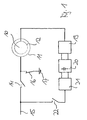
- FIG. 1 shows a schematic block diagram of an embodiment of an electrical circuit according to the invention for operating a double-fed Asynchronous machine
- FIG. 2 shows a schematic diagram of operating variables of the asynchronous machine of FIG. 1 ,
- FIG. 1 an electrical circuit of a phase of a double-fed asynchronous machine 10 is shown, which has a stator 11 and a rotor 12.
- the stator 11 is connected via a stator-side main switch 14 to a power supply network 15. Furthermore, it is provided that the phases of the stator 11 can be short-circuited to each other. This is in the embodiment of FIG. 1 realized by the fact that the phases of the stator 11 are connected via a short-circuit switch 16 to earth or ground 17.
- the rotor 12 is connected to an inverter 19, which in turn is connected to a rectifier 21 via a DC intermediate circuit 20.
- the rectifier 21 is connected via a rotor-side main switch 22 to the power supply network 15.
- IGBTs IGBTs
- GTO gate turn-off thyristors
- the DC intermediate circuit 20 may for example consist of one or more series-connected capacitor / s.
- the rectifier 21 may be a self-commutated converter, for example, which regulates the intermediate circuit voltage.
- a thyristor rectifier may be present.
- Both the inverter 19 and the rectifier 21 may be provided with further components for filtering the output voltage.
- the rectifier 21 may also have an upstream choke or a transformer for decoupling and / or voltage adjustment.
- the current supplied by the inverter 19 to the rotor 12 is hereinafter referred to as rotor current
- the voltage applied to the rotor 12 voltage is referred to as the rotor voltage
- the DC voltage present in the DC link 20 is referred to as DC link voltage.
- FIG. 2 The starting of the asynchronous machine 10 will be described below with reference to FIGS FIG. 2 explained.
- the values for the speed are in the FIG. 2 in revolutions per minute. It should be noted that in the FIG. 2 entered values for the speed have been selected only as an example and only for the purpose of description, and that these values may therefore differ significantly depending on an asynchronous machine 10 actually used.
- stator-side main switch 14 and the rotor-side main switch 22 are opened and the short-circuit switch 16 is closed.
- the stator 11 is thus shorted to earth, so that the individual windings of the stator 11 are short-circuited.
- This condition is in the FIG. 1 represented and corresponds to the state at zero speed in the FIG. 2 ,
- the rotor-side main switch 22 is transferred to its closed state and the rectifier 21 starts its operation.
- the rectifier 21 thus supplies the DC intermediate circuit 20 and causes the DC link voltage from the power supply network 15 is regulated to a predetermined value.
- any rotor voltage can be adjusted, with only one limitation is given by the size of the DC link voltage.
- the inverter 19 can now be controlled such that the rotor 12 as large a permissible rotor current is impressed.
- the asynchronous machine 10 is energized by the control of the inverter 19 and there is a magnetic flux with approximately constant amplitude. By a suitable change in the phase position of the rotor current, an approximately constant torque acting on the rotor 12 is produced. This is in the FIG. 2 marked with the reference a.
- the rotor voltage is increased by the inverter 19 according to a predetermined increase, for example, by pulse width modulation of the DC link voltage. This is in the FIG. 2 denoted by the reference b.
- the rotor voltage is kept at an approximately constant value W1, which typically corresponds approximately to the maximum output voltage of the inverter 19 at constant DC link voltage.
- W1 typically corresponds approximately to the maximum output voltage of the inverter 19 at constant DC link voltage.
- the DC link voltage has approximately reached its intended value for the nominal operation of the rectifier 21. This has the consequence that the magnetic flux decreases in amplitude and thus also the torque acting on the rotor 12. The latter is in the FIG. 2 denoted.
- the tilting moment K1 represents an upper limit for the torque that can be generated by the asynchronous machine 10, namely at the currently present DC link voltage and the resulting maximum rotor voltage.
- the over-speed, acting on the rotor 12 torque of the asynchronous machine 10 can not be greater than the respective associated tilting moment K1 at the set rotor voltage.
- the tilting moment K1 falls below the course of the torque acting on the rotor 12 at a speed of about 80 revolutions per minute. After falling below this, the rotor current is reduced in order to set the maximum possible overturning moment. The torque acting on the rotor 12 is then in accordance with the course of the tilting moment K1 with increasing speed always lower. This is in the FIG. 2 marked with the reference e.
- the torque acting on the rotor 12 has decreased to a value that is at the currently existing Speed would make a further increase in the speed of the asynchronous machine 10 only very slowly or not at all possible. This can be caused, for example, by a load torque increasing with the speed. From this speed, for example, 120 revolutions per minute, therefore, the rotor voltage is increased by the DC link voltage is increased. This is in the FIG. 2 marked with the reference f.
- the DC link voltage can be raised above the nominal value specified per se, since the rotor current has previously been reduced. This ensures overall that the rectifier 21, the DC intermediate circuit 20 and the inverter 19 are not overloaded.
- the rotor voltage can be increased by means of an increase of the DC bus voltage according to the FIG. 2 be increased in the form of a ramp to a value W2. It is also possible to provide any other transition curve for the elevation. It is also possible to change the rotor voltage almost abruptly to the value W2 by rapidly increasing the magnetic flux and feeding more current to form the torque.
- the value W2 of the rotor voltage includes a tilting moment K2. After reaching the value W2 of the rotor voltage, this is kept approximately constant. This is in the FIG. 2 marked with the reference h. At the same time the rotor current is reduced. This has the consequence that the torque acting on the rotor 12 again becomes smaller along the course of the tilting moment K2. This is in the FIG. 2 marked with the reference i.
- the reduction of the rotor current opens again the possibility that the DC link voltage and thus also the rotor voltage is further increased.
- the torque acting on the rotor 12 then initially remains approximately constant again and then decreases in accordance with the course of the tilting torque associated with the new DC link voltage. This procedure can be repeated several times.
- the rotor voltage can be raised to a value Wn, to which a tilting moment Kn belongs.
- the torque acting on the rotor 12 then runs according to this tilting moment Kn.
- the tilting moment Kn for larger rotational speeds of the asynchronous machine 10 is substantially greater than the initial tilting moment K1.
- the torque acting on the rotor 12 thus does not drop to the lower overturning moment K1 for larger rotational speeds, but a larger torque corresponding to the overturning moment Kn remains even at relatively high rotational speeds.
- an increase in the rotor voltage can also be achieved by increasing the modulation of the inverter 19 up to a so-called block cycle with a constant DC bus voltage be achieved. In this case, if necessary, the additional harmonics acting on the asynchronous machine 10 are taken into account.
- the asynchronous machine 10 is demagnetized by the fact that the amplitude and phase angle of the rotor current is selectively changed.
- the current component responsible for the magnetization is adjusted to negative values until demagnetization is achieved. Due to the existing high field weakening this demagnetization can be carried out within a very short period of time, in particular less than one second, so that this has essentially no influence on the rotational speed of the rotor 12.
- the rotor current is switched off via the inverter 19, in order to ensure that the short-circuit switch 16 can be opened almost without current.
- the asynchronous machine 10 is then magnetized again and synchronized with the power supply network 15. When this is achieved, the stator-side main switch 14 is closed. The asynchronous machine 10 is now operated in its normal operation.
- the short-circuit switch 16 as a circuit breaker or as a circuit breaker that can turn off sufficiently high currents, a prior demagnetization is not required.
- the rotor 12 can thus be further accelerated in normal operation by a correspondingly selected frequency of the rotor current and the rotor voltage to a desired speed.
Landscapes
- Engineering & Computer Science (AREA)
- Power Engineering (AREA)
- Control Of Ac Motors In General (AREA)
- Control Of Eletrric Generators (AREA)
Applications Claiming Priority (1)
| Application Number | Priority Date | Filing Date | Title |
|---|---|---|---|
| DE102008064078A DE102008064078A1 (de) | 2008-12-19 | 2008-12-19 | Verfahren zum Starten einer doppelt-gespeisten Asynchronmaschine |
Publications (3)
| Publication Number | Publication Date |
|---|---|
| EP2200169A2 true EP2200169A2 (fr) | 2010-06-23 |
| EP2200169A3 EP2200169A3 (fr) | 2012-03-07 |
| EP2200169B1 EP2200169B1 (fr) | 2014-04-02 |
Family
ID=41566315
Family Applications (1)
| Application Number | Title | Priority Date | Filing Date |
|---|---|---|---|
| EP09015242.2A Not-in-force EP2200169B1 (fr) | 2008-12-19 | 2009-12-09 | Procédé de démarrage d'une machine asynchrone à double alimentation |
Country Status (2)
| Country | Link |
|---|---|
| EP (1) | EP2200169B1 (fr) |
| DE (1) | DE102008064078A1 (fr) |
Cited By (3)
| Publication number | Priority date | Publication date | Assignee | Title |
|---|---|---|---|---|
| CN108347203A (zh) * | 2018-02-24 | 2018-07-31 | 易事特集团股份有限公司 | 无刷双馈电机控制方法、装置及系统 |
| EP3477847A1 (fr) * | 2017-10-25 | 2019-05-01 | Siemens Aktiengesellschaft | Machine asynchrone à double alimentation ainsi que procédé de fonctionnement d'une machine asynchrone à double alimentation |
| CN113236525A (zh) * | 2021-06-11 | 2021-08-10 | 西安热工研究院有限公司 | 汽动给水泵改造为双馈电机驱动给水泵的方法及启动方法 |
Families Citing this family (2)
| Publication number | Priority date | Publication date | Assignee | Title |
|---|---|---|---|---|
| DE102012021161A1 (de) * | 2012-10-29 | 2014-04-30 | Abb Technology Ag | Verfahren zum Betrieb einer Vorrichtung zur Speisung einer Asynchronmaschine |
| DE102018003031A1 (de) * | 2018-04-13 | 2019-10-17 | Senvion Gmbh | Windenergieanlage mit erweitertem Überdrehzahlregler |
Family Cites Families (4)
| Publication number | Priority date | Publication date | Assignee | Title |
|---|---|---|---|---|
| CH260941A (it) * | 1945-07-13 | 1949-04-15 | Ranzi Ubaldo | Gruppo motore elettrico-giunto, atto ad azionare macchine condotte a forte momento d'inerzia. |
| JPS63202290A (ja) * | 1987-02-14 | 1988-08-22 | Hitachi Ltd | 誘導機の速度制御方法 |
| DE20216775U1 (de) * | 2002-10-31 | 2003-01-02 | Alstom, Paris | Drehstrommotor mit einem Schleifringläufer und damit ausgestattete Transportanlage |
| EP1499009B1 (fr) * | 2003-07-15 | 2007-10-31 | Gamesa Innovation & Technology, S.L. Unipersonal | Commande et protection d'un système générateur à induction à double alimentation |
-
2008
- 2008-12-19 DE DE102008064078A patent/DE102008064078A1/de not_active Ceased
-
2009
- 2009-12-09 EP EP09015242.2A patent/EP2200169B1/fr not_active Not-in-force
Non-Patent Citations (1)
| Title |
|---|
| None |
Cited By (6)
| Publication number | Priority date | Publication date | Assignee | Title |
|---|---|---|---|---|
| EP3477847A1 (fr) * | 2017-10-25 | 2019-05-01 | Siemens Aktiengesellschaft | Machine asynchrone à double alimentation ainsi que procédé de fonctionnement d'une machine asynchrone à double alimentation |
| WO2019081366A1 (fr) | 2017-10-25 | 2019-05-02 | Siemens Aktiengesellschaft | Procédé de fonctionnement d'une machine asynchrone à double alimentation |
| CN111279606A (zh) * | 2017-10-25 | 2020-06-12 | 西门子股份公司 | 用于运行双馈异步电机的方法 |
| CN108347203A (zh) * | 2018-02-24 | 2018-07-31 | 易事特集团股份有限公司 | 无刷双馈电机控制方法、装置及系统 |
| CN113236525A (zh) * | 2021-06-11 | 2021-08-10 | 西安热工研究院有限公司 | 汽动给水泵改造为双馈电机驱动给水泵的方法及启动方法 |
| CN113236525B (zh) * | 2021-06-11 | 2022-08-30 | 西安热工研究院有限公司 | 汽动给水泵改造为双馈电机驱动给水泵的方法及启动方法 |
Also Published As
| Publication number | Publication date |
|---|---|
| EP2200169A3 (fr) | 2012-03-07 |
| DE102008064078A1 (de) | 2010-06-24 |
| EP2200169B1 (fr) | 2014-04-02 |
Similar Documents
| Publication | Publication Date | Title |
|---|---|---|
| DE102004003657B4 (de) | Stromrichterschaltungsanordnung und zugehöriges Ansteuerverfahren für Generatoren mit dynamisch veränderlicher Leistungsabgabe | |
| EP3644497B1 (fr) | Procédé et dispositif de commande virtuelle d'inertie de masse pour centrales pourvues de machine asynchrone à double alimentation | |
| EP1305876B1 (fr) | Procede pour reguler une machine electrique au moyen d'un onduleur pulse | |
| EP2457320A2 (fr) | Procédé de fonctionnement d'une turbine éolienne et turbine éolienne associée | |
| DE3015196C2 (de) | Verfahren und Anordnung zum Betrieb eines Wechselstrommotors bei Stillstand | |
| EP2200169B1 (fr) | Procédé de démarrage d'une machine asynchrone à double alimentation | |
| DE19735742B4 (de) | Über- und untersynchrone Stromrichterkaskade | |
| EP2541746B1 (fr) | Procédé de déchartge d'un condensateur de circuit intermédiaire d'un convertisseur et circuit correspondant | |
| EP2244372B1 (fr) | Dispositif de circuit pour une installation éolienne | |
| DE102021129144B4 (de) | Verfahren zum Betreiben einer elektrischen Schaltungsanordnung, elektrische Schaltung und Kraftfahrzeug | |
| EP3163733A1 (fr) | Convertisseur pour une machine électrique, dispositif d'entraînement électrique pour un véhicule automobile et procédé de fonctionnement d'un convertisseur | |
| EP1513251B1 (fr) | Procédé et dispositif d'exploitation d'une machine à courant alternatif à double alimentation en tant que génératrice dans une éolienne | |
| EP2117108B1 (fr) | Procédé de démarrage d'un système destiné à la production d'énergie électrique | |
| WO2004013953A1 (fr) | Systeme generateur-moteur et procede d'exploitation dudit systeme generateur-moteur | |
| DE2425362A1 (de) | Drehzahlveraenderliche elektrische antriebseinrichtung mit nutzbremsmoeglichkeit | |
| WO2012019834A2 (fr) | Système convertisseur et procédé de fonctionnement d'un système convertisseur de ce type | |
| WO2024184116A1 (fr) | Motif d'impulsion optimisé tenant compte des tensions induites dans la machine | |
| DE102017130869A1 (de) | Elektrisches Getriebe und Verfahren zum Betreiben eines Elektromotors | |
| EP3531547A1 (fr) | Circuit de commande permettant de coupler une machine synchrone avec un réseau de tension et procédé de fonctionnement dudit circuit | |
| EP3125401B1 (fr) | Éolienne comprenant une alimentation d'autoconsommation a tension regulee | |
| EP3172831A1 (fr) | Procédé de commande d'au moins une machine électrique pouvant fonctionner en générateur et moyen pour mettre en oeuvre celui-ci | |
| DE102015008436A1 (de) | Energieversorgungseinrichtung | |
| DE102008064079A1 (de) | Verfahren und elektrische Schaltung zur Erzeugung elektrischer Energie | |
| EP4002677A1 (fr) | Système de porte pour un véhicule doté d'une battant de porte et procédé de freinage sélectif d'un battant de porte à moteur électrique | |
| EP3349350A1 (fr) | Procédé de fonctionnement d'une machine asynchrone en mode générateur |
Legal Events
| Date | Code | Title | Description |
|---|---|---|---|
| PUAI | Public reference made under article 153(3) epc to a published international application that has entered the european phase |
Free format text: ORIGINAL CODE: 0009012 |
|
| AK | Designated contracting states |
Kind code of ref document: A2 Designated state(s): AT BE BG CH CY CZ DE DK EE ES FI FR GB GR HR HU IE IS IT LI LT LU LV MC MK MT NL NO PL PT RO SE SI SK SM TR |
|
| AX | Request for extension of the european patent |
Extension state: AL BA RS |
|
| PUAL | Search report despatched |
Free format text: ORIGINAL CODE: 0009013 |
|
| AK | Designated contracting states |
Kind code of ref document: A3 Designated state(s): AT BE BG CH CY CZ DE DK EE ES FI FR GB GR HR HU IE IS IT LI LT LU LV MC MK MT NL NO PL PT RO SE SI SK SM TR |
|
| AX | Request for extension of the european patent |
Extension state: AL BA RS |
|
| RIC1 | Information provided on ipc code assigned before grant |
Ipc: F03D 9/00 20060101ALI20120130BHEP Ipc: H02P 9/10 20060101ALI20120130BHEP Ipc: H02P 1/46 20060101AFI20120130BHEP Ipc: H02P 1/26 20060101ALI20120130BHEP |
|
| 17P | Request for examination filed |
Effective date: 20120831 |
|
| RIN1 | Information on inventor provided before grant (corrected) |
Inventor name: JANNING, JOERG, DR. |
|
| 16A | New documents despatched to applicant after publication of the search report |
Effective date: 20120925 |
|
| RIC1 | Information provided on ipc code assigned before grant |
Ipc: H02P 1/46 20060101AFI20130711BHEP Ipc: H02P 1/26 20060101ALI20130711BHEP Ipc: H02P 9/10 20060101ALI20130711BHEP Ipc: F03D 9/00 20060101ALI20130711BHEP |
|
| GRAP | Despatch of communication of intention to grant a patent |
Free format text: ORIGINAL CODE: EPIDOSNIGR1 |
|
| INTG | Intention to grant announced |
Effective date: 20130912 |
|
| RAP1 | Party data changed (applicant data changed or rights of an application transferred) |
Owner name: GE ENERGY POWER CONVERSION TECHNOLOGY LIMITED |
|
| GRAS | Grant fee paid |
Free format text: ORIGINAL CODE: EPIDOSNIGR3 |
|
| GRAA | (expected) grant |
Free format text: ORIGINAL CODE: 0009210 |
|
| AK | Designated contracting states |
Kind code of ref document: B1 Designated state(s): AT BE BG CH CY CZ DE DK EE ES FI FR GB GR HR HU IE IS IT LI LT LU LV MC MK MT NL NO PL PT RO SE SI SK SM TR |
|
| REG | Reference to a national code |
Ref country code: GB Ref legal event code: FG4D Free format text: NOT ENGLISH |
|
| REG | Reference to a national code |
Ref country code: AT Ref legal event code: REF Ref document number: 660654 Country of ref document: AT Kind code of ref document: T Effective date: 20140415 Ref country code: CH Ref legal event code: EP |
|
| REG | Reference to a national code |
Ref country code: IE Ref legal event code: FG4D Free format text: LANGUAGE OF EP DOCUMENT: GERMAN |
|
| REG | Reference to a national code |
Ref country code: DE Ref legal event code: R096 Ref document number: 502009009085 Country of ref document: DE Effective date: 20140515 |
|
| REG | Reference to a national code |
Ref country code: NL Ref legal event code: VDEP Effective date: 20140402 |
|
| REG | Reference to a national code |
Ref country code: LT Ref legal event code: MG4D |
|
| PG25 | Lapsed in a contracting state [announced via postgrant information from national office to epo] |
Ref country code: NL Free format text: LAPSE BECAUSE OF FAILURE TO SUBMIT A TRANSLATION OF THE DESCRIPTION OR TO PAY THE FEE WITHIN THE PRESCRIBED TIME-LIMIT Effective date: 20140402 Ref country code: LT Free format text: LAPSE BECAUSE OF FAILURE TO SUBMIT A TRANSLATION OF THE DESCRIPTION OR TO PAY THE FEE WITHIN THE PRESCRIBED TIME-LIMIT Effective date: 20140402 Ref country code: CZ Free format text: LAPSE BECAUSE OF FAILURE TO SUBMIT A TRANSLATION OF THE DESCRIPTION OR TO PAY THE FEE WITHIN THE PRESCRIBED TIME-LIMIT Effective date: 20140402 Ref country code: BG Free format text: LAPSE BECAUSE OF FAILURE TO SUBMIT A TRANSLATION OF THE DESCRIPTION OR TO PAY THE FEE WITHIN THE PRESCRIBED TIME-LIMIT Effective date: 20140702 Ref country code: IS Free format text: LAPSE BECAUSE OF FAILURE TO SUBMIT A TRANSLATION OF THE DESCRIPTION OR TO PAY THE FEE WITHIN THE PRESCRIBED TIME-LIMIT Effective date: 20140802 Ref country code: GR Free format text: LAPSE BECAUSE OF FAILURE TO SUBMIT A TRANSLATION OF THE DESCRIPTION OR TO PAY THE FEE WITHIN THE PRESCRIBED TIME-LIMIT Effective date: 20140703 Ref country code: NO Free format text: LAPSE BECAUSE OF FAILURE TO SUBMIT A TRANSLATION OF THE DESCRIPTION OR TO PAY THE FEE WITHIN THE PRESCRIBED TIME-LIMIT Effective date: 20140702 Ref country code: FI Free format text: LAPSE BECAUSE OF FAILURE TO SUBMIT A TRANSLATION OF THE DESCRIPTION OR TO PAY THE FEE WITHIN THE PRESCRIBED TIME-LIMIT Effective date: 20140402 Ref country code: CY Free format text: LAPSE BECAUSE OF FAILURE TO SUBMIT A TRANSLATION OF THE DESCRIPTION OR TO PAY THE FEE WITHIN THE PRESCRIBED TIME-LIMIT Effective date: 20140402 |
|
| PG25 | Lapsed in a contracting state [announced via postgrant information from national office to epo] |
Ref country code: SE Free format text: LAPSE BECAUSE OF FAILURE TO SUBMIT A TRANSLATION OF THE DESCRIPTION OR TO PAY THE FEE WITHIN THE PRESCRIBED TIME-LIMIT Effective date: 20140402 Ref country code: LV Free format text: LAPSE BECAUSE OF FAILURE TO SUBMIT A TRANSLATION OF THE DESCRIPTION OR TO PAY THE FEE WITHIN THE PRESCRIBED TIME-LIMIT Effective date: 20140402 Ref country code: PL Free format text: LAPSE BECAUSE OF FAILURE TO SUBMIT A TRANSLATION OF THE DESCRIPTION OR TO PAY THE FEE WITHIN THE PRESCRIBED TIME-LIMIT Effective date: 20140402 Ref country code: ES Free format text: LAPSE BECAUSE OF FAILURE TO SUBMIT A TRANSLATION OF THE DESCRIPTION OR TO PAY THE FEE WITHIN THE PRESCRIBED TIME-LIMIT Effective date: 20140402 Ref country code: HR Free format text: LAPSE BECAUSE OF FAILURE TO SUBMIT A TRANSLATION OF THE DESCRIPTION OR TO PAY THE FEE WITHIN THE PRESCRIBED TIME-LIMIT Effective date: 20140402 |
|
| PG25 | Lapsed in a contracting state [announced via postgrant information from national office to epo] |
Ref country code: PT Free format text: LAPSE BECAUSE OF FAILURE TO SUBMIT A TRANSLATION OF THE DESCRIPTION OR TO PAY THE FEE WITHIN THE PRESCRIBED TIME-LIMIT Effective date: 20140804 |
|
| REG | Reference to a national code |
Ref country code: DE Ref legal event code: R097 Ref document number: 502009009085 Country of ref document: DE |
|
| PG25 | Lapsed in a contracting state [announced via postgrant information from national office to epo] |
Ref country code: DK Free format text: LAPSE BECAUSE OF FAILURE TO SUBMIT A TRANSLATION OF THE DESCRIPTION OR TO PAY THE FEE WITHIN THE PRESCRIBED TIME-LIMIT Effective date: 20140402 Ref country code: RO Free format text: LAPSE BECAUSE OF FAILURE TO SUBMIT A TRANSLATION OF THE DESCRIPTION OR TO PAY THE FEE WITHIN THE PRESCRIBED TIME-LIMIT Effective date: 20140402 Ref country code: EE Free format text: LAPSE BECAUSE OF FAILURE TO SUBMIT A TRANSLATION OF THE DESCRIPTION OR TO PAY THE FEE WITHIN THE PRESCRIBED TIME-LIMIT Effective date: 20140402 Ref country code: SK Free format text: LAPSE BECAUSE OF FAILURE TO SUBMIT A TRANSLATION OF THE DESCRIPTION OR TO PAY THE FEE WITHIN THE PRESCRIBED TIME-LIMIT Effective date: 20140402 |
|
| PLBE | No opposition filed within time limit |
Free format text: ORIGINAL CODE: 0009261 |
|
| STAA | Information on the status of an ep patent application or granted ep patent |
Free format text: STATUS: NO OPPOSITION FILED WITHIN TIME LIMIT |
|
| 26N | No opposition filed |
Effective date: 20150106 |
|
| PG25 | Lapsed in a contracting state [announced via postgrant information from national office to epo] |
Ref country code: IT Free format text: LAPSE BECAUSE OF FAILURE TO SUBMIT A TRANSLATION OF THE DESCRIPTION OR TO PAY THE FEE WITHIN THE PRESCRIBED TIME-LIMIT Effective date: 20140402 |
|
| REG | Reference to a national code |
Ref country code: DE Ref legal event code: R097 Ref document number: 502009009085 Country of ref document: DE Effective date: 20150106 |
|
| PG25 | Lapsed in a contracting state [announced via postgrant information from national office to epo] |
Ref country code: BE Free format text: LAPSE BECAUSE OF NON-PAYMENT OF DUE FEES Effective date: 20141231 |
|
| PG25 | Lapsed in a contracting state [announced via postgrant information from national office to epo] |
Ref country code: SI Free format text: LAPSE BECAUSE OF FAILURE TO SUBMIT A TRANSLATION OF THE DESCRIPTION OR TO PAY THE FEE WITHIN THE PRESCRIBED TIME-LIMIT Effective date: 20140402 Ref country code: LU Free format text: LAPSE BECAUSE OF FAILURE TO SUBMIT A TRANSLATION OF THE DESCRIPTION OR TO PAY THE FEE WITHIN THE PRESCRIBED TIME-LIMIT Effective date: 20141209 |
|
| REG | Reference to a national code |
Ref country code: CH Ref legal event code: PL |
|
| REG | Reference to a national code |
Ref country code: IE Ref legal event code: MM4A |
|
| PG25 | Lapsed in a contracting state [announced via postgrant information from national office to epo] |
Ref country code: LI Free format text: LAPSE BECAUSE OF NON-PAYMENT OF DUE FEES Effective date: 20141231 Ref country code: IE Free format text: LAPSE BECAUSE OF NON-PAYMENT OF DUE FEES Effective date: 20141209 Ref country code: CH Free format text: LAPSE BECAUSE OF NON-PAYMENT OF DUE FEES Effective date: 20141231 |
|
| REG | Reference to a national code |
Ref country code: FR Ref legal event code: PLFP Year of fee payment: 7 |
|
| REG | Reference to a national code |
Ref country code: AT Ref legal event code: MM01 Ref document number: 660654 Country of ref document: AT Kind code of ref document: T Effective date: 20141209 |
|
| PG25 | Lapsed in a contracting state [announced via postgrant information from national office to epo] |
Ref country code: SM Free format text: LAPSE BECAUSE OF FAILURE TO SUBMIT A TRANSLATION OF THE DESCRIPTION OR TO PAY THE FEE WITHIN THE PRESCRIBED TIME-LIMIT Effective date: 20140402 |
|
| PG25 | Lapsed in a contracting state [announced via postgrant information from national office to epo] |
Ref country code: AT Free format text: LAPSE BECAUSE OF NON-PAYMENT OF DUE FEES Effective date: 20141209 Ref country code: MC Free format text: LAPSE BECAUSE OF FAILURE TO SUBMIT A TRANSLATION OF THE DESCRIPTION OR TO PAY THE FEE WITHIN THE PRESCRIBED TIME-LIMIT Effective date: 20140402 |
|
| PG25 | Lapsed in a contracting state [announced via postgrant information from national office to epo] |
Ref country code: TR Free format text: LAPSE BECAUSE OF FAILURE TO SUBMIT A TRANSLATION OF THE DESCRIPTION OR TO PAY THE FEE WITHIN THE PRESCRIBED TIME-LIMIT Effective date: 20140402 Ref country code: MT Free format text: LAPSE BECAUSE OF FAILURE TO SUBMIT A TRANSLATION OF THE DESCRIPTION OR TO PAY THE FEE WITHIN THE PRESCRIBED TIME-LIMIT Effective date: 20140402 Ref country code: HU Free format text: LAPSE BECAUSE OF FAILURE TO SUBMIT A TRANSLATION OF THE DESCRIPTION OR TO PAY THE FEE WITHIN THE PRESCRIBED TIME-LIMIT; INVALID AB INITIO Effective date: 20091209 |
|
| REG | Reference to a national code |
Ref country code: FR Ref legal event code: PLFP Year of fee payment: 8 |
|
| REG | Reference to a national code |
Ref country code: FR Ref legal event code: PLFP Year of fee payment: 9 |
|
| PG25 | Lapsed in a contracting state [announced via postgrant information from national office to epo] |
Ref country code: MK Free format text: LAPSE BECAUSE OF FAILURE TO SUBMIT A TRANSLATION OF THE DESCRIPTION OR TO PAY THE FEE WITHIN THE PRESCRIBED TIME-LIMIT Effective date: 20140402 |
|
| PGFP | Annual fee paid to national office [announced via postgrant information from national office to epo] |
Ref country code: GB Payment date: 20231121 Year of fee payment: 15 |
|
| PGFP | Annual fee paid to national office [announced via postgrant information from national office to epo] |
Ref country code: FR Payment date: 20231122 Year of fee payment: 15 Ref country code: DE Payment date: 20231121 Year of fee payment: 15 |
|
| REG | Reference to a national code |
Ref country code: DE Ref legal event code: R119 Ref document number: 502009009085 Country of ref document: DE |
|
| GBPC | Gb: european patent ceased through non-payment of renewal fee |
Effective date: 20241209 |
|
| PG25 | Lapsed in a contracting state [announced via postgrant information from national office to epo] |
Ref country code: DE Free format text: LAPSE BECAUSE OF NON-PAYMENT OF DUE FEES Effective date: 20250701 |
|
| PG25 | Lapsed in a contracting state [announced via postgrant information from national office to epo] |
Ref country code: GB Free format text: LAPSE BECAUSE OF NON-PAYMENT OF DUE FEES Effective date: 20241209 |
|
| PG25 | Lapsed in a contracting state [announced via postgrant information from national office to epo] |
Ref country code: FR Free format text: LAPSE BECAUSE OF NON-PAYMENT OF DUE FEES Effective date: 20241231 |