EP2200184A1 - Procédé pour augmenter les performances d'un système de communications sur un support formé de multiples conducteurs - Google Patents
Procédé pour augmenter les performances d'un système de communications sur un support formé de multiples conducteurs Download PDFInfo
- Publication number
- EP2200184A1 EP2200184A1 EP08805326A EP08805326A EP2200184A1 EP 2200184 A1 EP2200184 A1 EP 2200184A1 EP 08805326 A EP08805326 A EP 08805326A EP 08805326 A EP08805326 A EP 08805326A EP 2200184 A1 EP2200184 A1 EP 2200184A1
- Authority
- EP
- European Patent Office
- Prior art keywords
- modes
- communications system
- performance
- injection
- increasing
- Prior art date
- Legal status (The legal status is an assumption and is not a legal conclusion. Google has not performed a legal analysis and makes no representation as to the accuracy of the status listed.)
- Granted
Links
Images


Classifications
-
- H—ELECTRICITY
- H04—ELECTRIC COMMUNICATION TECHNIQUE
- H04B—TRANSMISSION
- H04B3/00—Line transmission systems
-
- H—ELECTRICITY
- H04—ELECTRIC COMMUNICATION TECHNIQUE
- H04B—TRANSMISSION
- H04B3/00—Line transmission systems
- H04B3/54—Systems for transmission via power distribution lines
-
- H—ELECTRICITY
- H04—ELECTRIC COMMUNICATION TECHNIQUE
- H04B—TRANSMISSION
- H04B3/00—Line transmission systems
- H04B3/02—Details
- H04B3/32—Reducing cross-talk, e.g. by compensating
-
- H—ELECTRICITY
- H04—ELECTRIC COMMUNICATION TECHNIQUE
- H04L—TRANSMISSION OF DIGITAL INFORMATION, e.g. TELEGRAPHIC COMMUNICATION
- H04L25/00—Baseband systems
- H04L25/02—Details ; arrangements for supplying electrical power along data transmission lines
- H04L25/0264—Arrangements for coupling to transmission lines
- H04L25/0272—Arrangements for coupling to multiple lines, e.g. for differential transmission
- H04L25/0276—Arrangements for coupling common mode signals
-
- H—ELECTRICITY
- H04—ELECTRIC COMMUNICATION TECHNIQUE
- H04L—TRANSMISSION OF DIGITAL INFORMATION, e.g. TELEGRAPHIC COMMUNICATION
- H04L5/00—Arrangements affording multiple use of the transmission path
- H04L5/14—Two-way operation using the same type of signal, i.e. duplex
- H04L5/143—Two-way operation using the same type of signal, i.e. duplex for modulated signals
-
- H—ELECTRICITY
- H04—ELECTRIC COMMUNICATION TECHNIQUE
- H04L—TRANSMISSION OF DIGITAL INFORMATION, e.g. TELEGRAPHIC COMMUNICATION
- H04L5/00—Arrangements affording multiple use of the transmission path
- H04L5/20—Arrangements affording multiple use of the transmission path using different combinations of lines, e.g. phantom working
-
- H—ELECTRICITY
- H04—ELECTRIC COMMUNICATION TECHNIQUE
- H04J—MULTIPLEX COMMUNICATION
- H04J13/00—Code division multiplex systems
- H04J13/0007—Code type
- H04J13/004—Orthogonal
-
- H—ELECTRICITY
- H04—ELECTRIC COMMUNICATION TECHNIQUE
- H04L—TRANSMISSION OF DIGITAL INFORMATION, e.g. TELEGRAPHIC COMMUNICATION
- H04L5/00—Arrangements affording multiple use of the transmission path
- H04L5/0001—Arrangements for dividing the transmission path
- H04L5/0003—Two-dimensional division
- H04L5/0005—Time-frequency
- H04L5/0007—Time-frequency the frequencies being orthogonal, e.g. OFDM(A) or DMT
Definitions
- the present invention relates to a method for increasing the performance of a communications system on a medium formed by multiple conductors.
- any communications system the attempt is made to use to a maximum the characteristics of the communication medium to achieve maximum transmission capacity, reliability, coverage, etc.
- the communications medium is formed by multiple conductors, it is possible to use said conductors to achieve one or several of these objectives.
- the method described in the present invention is used in a medium formed by multiple conductors both to improve the performance of the communication, and to increase the reuse of used frequencies, or to improve repetition, among other applications.
- Communications systems need a transmission medium for signals that is often formed by multiple conductors.
- the presence of these multiple conductors can be used to improve different features of the communications system, such as the transmission capacity or noise immunity, among others.
- the present invention presents a new solution which optimally uses the multiplicity of conductors for increasing the performance of the transmission in the medium.
- Mode is understood as the injection of voltage or current on a selective combination of conductors, reference plane or both.
- orthogonal multi-injection is defined as an injection of multiple modes orthogonal to one another.
- the injection modes are divided into common mode, differential modes and pseudo-differential modes.
- the common mode is what causes the circulation of currents through the reference plane.
- the differential modes consist of the injection through one conductor and the return through another one, whereas the pseudo-differential modes consist of the injection of voltage or current between one or more conductors and the return through one or more conductors different from those used for the injection, the number of conductors used in this case being more than two.
- the patent "Space time coded data transmission via inductive effect between adjacent power lines” ( GB238372A ), describes the use of multiple paths for the communications signal on the electric network and in the digital processing application for identifying in each node the best time periods and frequency for communicating. Furthermore, in this document, the channel is treated as a system of multiple inputs and multiple outputs wherein the signal is coupled between the different conductors to reach the nodes through several paths. This document does not affect the novelty or the inventive step of the present invention, because orthogonal multiple injections are not performed on a multi-conductor medium, but rather a different method is applied to perform the communications which seeks to use the crosstalk between conductors instead of eliminating it.
- the present invention uses orthogonal injection modes in N cables seeking to achieve up to N independent communication channels, using said orthogonality for increasing the performance of a communication system preventing crosstalk instead of enhancing it, which is neither anticipated nor is it an evident result for a person having average skill in the art from this publication.
- the state of the art prior to the present patent also includes the publication " Vectored Transmission for Digital Subscriber Line Systems” (George Ginis, John M. Cioffi, IEEE Journal On Selected Areas in Communications, Vol. 20, No. 5, June 2002 ) in which the manner of increasing the transmission rate in a bundle of twisted pairs is described, wherein the injection in said twisted pairs is done in a differential manner, coordinating the transmissions and using techniques for multiple input and multiple output (MIMO) to cancel the crosstalk.
- MIMO multiple input and multiple output
- the invention consists of a method for increasing the performance of a communications system on a medium formed by multiple conductors and a reference plane, wherein the number of conductors will generally be N.
- Said method is characterized in that communication signals are injected in up to N modes, one mode being the injection of voltage or current on a selective combination between conductors, reference plane or both, such that said modes are orthogonal to one another.
- the method is suitable for any medium with multiple conductors, one of these media being the electric network.
- An application of the method consists of the transmitting equipment simultaneously injecting in up to N modes of the differential, pseudo-differential and common modes in the communication process, such that the transmission capacity in the communications system is multiplied without using extra digital processing.
- the transmitting equipment injects a signal simultaneously on the same bandwidth or frequency range to achieve the multiplication of the transmission capacity.
- Another possible application of the method of the invention is to increase the attenuation between communications networks and to improve the coexistence of said networks in one and the same medium.
- each of the communication networks coexisting in one and the same physical medium will use a different set of injection modes, from among the N possible modes, such that the sets of injection modes selected by the different communication networks are disjunctive.
- repeaters In multiple communications systems, it is necessary to use repeaters so that the signal from one piece of equipment can reach other distant equipment (in terms of attenuation).
- Said repeaters are usually frequency repeaters, i.e., they communicate with a group of nodes using a frequency band and repeat the signal for another group of nodes using another different frequency band.
- This type of repeaters normally use coexistence filters to cancel out the interference between the different frequency bands used for repeating.
- said repeaters can be made to use different injection modes from among the N possible modes, such that the specifications of the filters necessary for reducing the interference between the different frequency bands used by the repeater are relaxed, or even the need for said filters is eliminated.
- Another case of interference when using frequency repeaters occurs when the equipment forming the communications system reuses the same frequencies in remote links.
- interference will occur between equipment using the same frequencies, unless the pieces of equipment are so far from each other (in terms of attenuation) that the signals sent by one piece of equipment cannot be distinguished from the ground noise picked up by the other piece of equipment.
- the method of the invention can be used to improve this case, so the pieces of equipment forming the communication system will reuse the same frequencies without causing interference among one another by means of using different injection modes in the communication equipment of the remote links, such that greater flexibility is allowed in the reuse of frequency ranges in the planning of communications networks.
- the method can also be used to improve the reliability of the communication, so multiple versions of the communications signal will be transmitted in the injection modes used to subsequently combine them at reception.
- the use of multiple injection modes at transmission and at reception allows applying techniques for the multiple input and multiple output (MIMO) digital processing of communications signals, in the injection modes used from among the N possible modes. As a result, it is possible to improve the performance of the communication.
- MIMO multiple input and multiple output
- One of the MIMO techniques that can be applied is space-time coding.
- the method is applied together with space-time coding techniques consisting of distributing the communications signal among the injection modes used, such that the coding gain and diversity are exploited at the same time.
- eigenmode transmission Another possibility is that techniques for the transmission through channel eigenvectors (eigenmode transmission) are applied together with the inventive method at transmission and at reception to allow the receiver to decode the signals received through each of the injection modes used.
- a third possibility is that the method includes techniques for digital processing which allow canceling the interference or crosstalk between the injection modes used at reception, such that it increases the signal-to-noise ratio (SNR) detected in each of said injection modes, and thereby the performance of the communications.
- SNR signal-to-noise ratio
- Another application of the method is to achieve bidirectional communications.
- the communications system is formed by two pieces of equipment
- these pieces of equipment are bidirectionally communicated at the same time (full-duplex communication) for which purpose a first piece of equipment uses a set of injection modes from among the N possible modes to transmit to the second piece of equipment and another set of different injection modes to receive the signals from the second piece of equipment, whereas the second piece of equipment uses the first set to receive and the second set to transmit, wherein said sets are disjunctive.
- the method is characterized in that a piece of equipment transmits simultaneously to other pieces of equipment using a set of injection modes for the transmission to each piece of receiving equipment, wherein said sets are disjunctive.
- a piece of equipment receives simultaneously from other pieces of equipment using a set of injection modes for the reception from each piece of transmitting equipment, wherein said sets are disjunctive.
- the transmissions performed by different injection modes typically experience the channel characteristics in different ways: attenuation, interference, noise threshold, etc.
- Some examples of the communication characteristics which allow selecting the injection modes are: the noise present in the injection mode, the interference present in the injection mode, the stability of the channel in the injection mode, the radiation caused by the injection mode, the attenuation of the channel in the injection mode or a combination of the foregoing.
- different techniques for digital processing, different injection modes or a combination of techniques for digital processing and injection modes can be used in groups formed by one or several OFDM modulation carriers.
- the problem which the method of the invention wishes to resolve, from a theoretical point of view, consists of how to use the property that the transmission medium is formed by multiple conductors to maximize the performance of a communications system using said transmission medium.
- the multi-conductor medium Before describing several embodiments of communication systems using the method of the invention, the multi-conductor medium will be theoretically analyzed, which will allow justifying the validity of the method of the invention. From a theoretical point of view, it is possible to mathematically describe a multi-conductor medium with N parallel conductors referring to a reference plane which conduct signals between a source and a load by means of the MTL (multi-conductor transmission line) theory.
- MTL multi-conductor transmission line
- the dominant mode of propagating these signals is the transverse electromagnetic mode (TEM), in which both the electric field and the magnetic field are propagated orthogonally in the plane perpendicular to the axis of the conductors.
- TEM transverse electromagnetic mode
- These structures can propagate signals from direct current (zero frequency) to frequencies with a wavelength comparable to the size of the cross section of the conductor.
- the MTL theory for parallel conductors can be used more reliably for modeling the more dominant the TEM modes are. When frequency increases, they will begin to be contributive modes of a greater order than TEM and, therefore, the approaches made by the MTL theory will no longer be valid. Even when the TEM mode is dominant, the medium is actually not homogenous and the spatial geometry or the intrinsic characteristics thereof are not maintained, making them quasi-TEM modes, the propagation and isolation characteristics of which between injections are impaired. In any case, the MTL theory is used to describe the basis on which the method of the invention is supported.
- the signals that are injected in the different conductors of the medium generate an electromagnetic field causing signal coupling between conductors, the so-called crosstalk being generated.
- One of the main purposes of the MTL theory is to predict said crosstalk.
- the MTL theory in the simplest case of two conductors is reduced to having two modes for the spatial propagation of the signal, the common mode and the differential mode. It is typically the differential mode that is used to transport the energy of the data signals which are transmitted in actual applications (for example, communications through the electric network).
- the common mode is injected in both conductors and the return is through the reference plane or ground, whereas the differential mode consists of injecting through one conductor and the return through the other one.
- the common mode has greater losses and the added drawback of radiating more than the differential mode, making its use more limited at the level of complying with emissions regulating standards. Even when trying to avoid the common mode, any differential signal propagated through a channel will have a common mode conversion factor due to asymmetries and unbalancing of the channel.
- I c is the common mode current
- the system relating the currents through the conductors with the currents of each mode is orthogonal, i.e., it is an independent linear system, and furthermore the current vectors of each mode are orthogonal. Since it is an independent system, the range of the matrix A is equal to N; whereas since the modes are orthogonal, the product of the matrix A transposed by A is a diagonal matrix.
- Figure 1 shows an example of the propagation modes existing in the specific case of the electric network when injecting in common mode (1) and in differential mode (2), when the network is formed by only two conductors (3) and the reference plane or ground circuit (4).
- the common mode current I c is distributed through the multiple conductors and returns through the reference plane, whereas the differential current is injected through one conductor and returns through the other one.
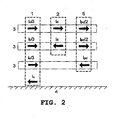
- the propagation modes will be the same as with two conductors, plus a mode referred to as pseudo-differential mode, in which the current circulates through two of the conductors and returns through the third one.
- pseudo-differential mode a mode referred to as pseudo-differential mode, in which the current circulates through two of the conductors and returns through the third one.
- the pseudo-differential has optimal characteristics for signal propagation since it has low attenuation in the channel, and it is orthogonal to the other two, as can be mathematically shown.
- Figure 2 shows the orthogonal injection modes for the case of the electric network formed by three conductors (3) together with the reference plane (4).
- the injection can be performed in a pseudo-differential manner (5).
- the inventive method allows, among other applications, maintaining a useful signal level that is sufficient for using the possibility of having the bandwidth of the medium multiplied by a factor of up to N-1 (without using the common mode), without having increased the frequency spectrum used, i.e., injecting different signals using the same bandwidth in the channel and improving by N-1 the number of signals between an emitter and a receiver or between an emitter and several receivers.
- An immediate application of the method of the invention is a communication system in which the transmitter simultaneously injects up to N different modes of the possible modes (differential, pseudo-differential and common modes) to multiply the transmission capacity of the system with the advantage of not needing any extra digital processing and without expanding the frequency range.
- FIG. 4 An example of simultaneous orthogonal multi-transmission in a point-to-point link such as the one just described can be seen in Figure 4 , in which there is a transmitting node (11) and a receiving node (12) which are communicated by a transmission medium (10) formed by N conductors on a bandwidth limited by the frequencies f 1 and f 2 .
- the crosstalk is also depicted in this figure by means of dotted lines (30).
- the output of the modulator/demodulator (6) of the transmitter consists of N different signals which are converted from digital to analog (DAC 1 to DAC N ).
- Each signal is amplified analogically (AFE module) (7) (S 1 to S N ) and are injected (TXi to TX N ) orthogonally into the medium (10) through the coupler (8). Therefore, the signal on the transmitter medium is a signal formed by N signals on the same bandwidth (9).
- the opposite is done at reception, taking the signals with the coupler (8), which will be affected by the communication channel (S' 1 to S' N ) characteristics, obtaining N signals (RX 1 to RX N ), amplifying them with an AFE module (7).
- the signals are then passed to the digital domain (ADC 1 to ADC N ), and are finally introduced in the modulator/demodulator (6) to retrieve the transmitted information.
- Another embodiment of the method of the invention improves the coexistence of networks sharing one and the same transmission medium.
- Any communication system has a maximum operating range in terms of maximum distance that can be reached due to the attenuation of the medium, the interference of nodes of other networks and the noise present in the medium, among other degradations. Beyond this range, the communication between nodes cannot be carried out.
- the element limiting the operating range of a node is the presence of a signal from another node belonging to another communications network sharing the medium, the signal will experience degradation of its performance due to this interference. Said nodes must coexist in the same medium, and it would be desirable for said coexistence to be carried out with the lowest possible loss of performance.
- the use of the method of the invention allows two nodes within the communication range to operate independently without negatively affecting the performance due to the interference between them.
- the attenuation between networks present in one and the same medium is greater, provided that each of them uses a different injection mode, even when using the same frequency band.
- Figure 5 shows two networks, each of which has to provide coverage to an area, Network 1 (13) provides coverage a Area 1 (14), whereas Network 2 (15) provides coverage to Area 2 (16).
- Both networks share the physical medium (10) and will generally have a larger area of action than the area which they should cover. This is a determining factor for interference between networks. The greater the power transmitted by a network, the greater its coverage or range and the more possibilities it will have of interfering with other networks. In this case there is an area of interference (17) in which the signals of both networks are mixed. Reducing the power transmitted by the network would improve the coexistence with other networks but, in most cases, it would impair the performance in its own coverage area, so it is actually not a feasible solution.
- the method of the invention can also be applied for increasing the performance of the systems.
- a communications network formed by multi-conductors it is possible that the necessary coverage is not reached and it is necessary to use repeaters which allow increasing the coverage area of the network.
- Repeaters typically use time division techniques (TDD) or frequency division techniques (FDD).
- TDD time division techniques
- FDD frequency division techniques
- TDD techniques with the multi-injection used the bandwidth of the channel is increased without increasing the frequencies used, this means that the reduction of the performance involved in TDD in a network is minimized when taking into account the performance of the network as a whole.
- FDD frequency division
- the use of the method allows relaxing the characteristics of these coexistence filters in adjacent links and even eliminating them under certain conditions.
- Another application of the method of the invention is the capacity of achieving full-duplex communication between pieces of equipment, i.e., transmitting and receiving information simultaneously between the pieces of equipment, using orthogonal multi-injection.
- An example can be a medium voltage line of the electric network with broadband communication equipment, as can be seen in Figure 8 .
- the network is a three phase network, it is possible to perform a multi-injection on three conductors, wherein a differential mode (2) and a pseudo-differential mode (5) are injected, so a full-duplex channel is obtained using the same frequency band on the same communications channel between the equipment (23).
- the method of the invention can be applied together with techniques for MIMO (multiple-input, multiple-output) to improve the performance of the communications system using said techniques.
- MIMO multiple-input, multiple-output
- NxN multiple-input, multiple-output
- the use of orthogonal multi-injection allows obtaining channel matrices that are better conditioned, so the application of techniques for MIMO will be more efficient.
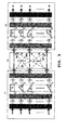
- Figure 9 shows an embodiment in which the system uses MIMO digital processing and the method of the invention.
- This example continues the general scheme of the communications system shown in the previous figures and a module for the digital processing of multiple input signals (a 1 ...a N ) and multiple output signals (29) is included therein.
- the crosstalk or interference between the injected signals (30) that can be used or reduced using MIMO digital processing has been marked in the figure in this case.
- diversity techniques in the field of telecommunications relate to an improvement of the reliability of a signal traveling through a medium, using two or more communication channels with different characteristics. These techniques exploit the different characteristics of the N communication channels to increase the robustness of the receiver, to prevent chain bit errors and to control signal fading.
- the method consists of transmitting multiple signal versions which are combined in the receiver to improve the reliability of the communication. Error correction techniques can be incorporated in the different transmitted signals in different parts of each message of each channel.
- the embodiment of Figure 10 shows a system in which the inventive method is used together with the transmission of multiple versions of one and the same communications signal in the injection modes used and the result is combined at reception. It is thus possible to improve the reliability of the communication.
- Figure 10 shows this example, in which the symbol to be transmitted (27) is processed digitally (6), passes to the analog domain and is suitably amplified (7) and finally coupled (8), introducing the same signal with each of the orthogonal injection modes. The opposite is done at reception, taking the signal of each orthogonal injection, amplifying it and finally making a combination (28) of the obtained signals.
- This combination consists of multiplying each signal by a weight (which depends in this embodiment on the signal-to-noise ratio perceived in the channel formed by the orthogonal injection) and adding the results to try to obtain the symbol sent.
- the replica of the transmitted signal and its combination at reception allows increasing the reliability of the communication even in scenarios that are extremely degraded due to noises or interferences.
- the method of multi-injection can be applied to spatial diversity, wherein the signal is transmitted through different paths of the same medium.
- Diversity combining techniques can be used before signal processing, selecting the strongest signal reaching the receiver, changing the channel when the signal does not have a minimal performance, or coherently adding up all the receptions, using MRC (maximal-ratio combining) wherein weights are applied to the received signals depending on the signal-to-noise ratio (SNR) of each one, before adding up the receptions.
- SNR signal-to-noise ratio
- the previously mentioned techniques can be extended, giving rise to space-time coding techniques. By means of this coding, the information and the redundancy are uniformly distributed among the N communication paths to exploit the diversity and coding gain of determined codes at the same time.
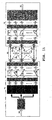
- FIG. 11 A specific example can be seen in Figure 11 , in which the digital processing module (29) for processing multiple input signals (a 1 ...a N ) and multiple output signals (DAC 1 ...DAC N ) of Figure 9 has been replaced at transmission with a space-time coder (32) which the symbols to be transmitted (31) reach. At reception, the digital processing is replaced with a space-time demodulating and decoding module (33) which obtains the digital symbols (31) sent from the transmitter.
- the isolation provided by orthogonal injections can be increased by means of digital processing .
- a specific embodiment of MIMO processing will consist of techniques for transmission through the channel eigenvectors which linearly combine the signals to be transmitted in each of the injection modes (by means of products and sums of the signals obtained from digital processing) and the signals received in each of the injection modes.
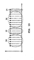
- Figure 12 shows this embodiment, wherein N symbols (31) are introduced in digital processing (6) and the outputs are linearly combined by means of multipliers (41) and adders (42) with weights (generally different for the transmitter (43) and (44) and for the receiver (45) and (46)) the value of which is calculated depending on the specific transmission medium of the application. Processing at reception is identical to the processing performed at transmission.
- MIMO processing can also be used to reduce and even eliminate crosstalk between channels (30).
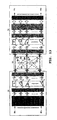
- the scheme seen in the example of Figure 13 can be used, wherein the receiver includes a crosstalk canceller (34) which reduces interference of the other injection modes on each of the injection modes due to crosstalk.
- Another embodiment of the invention consists of applying the method of the invention in a communications system such that the same signal is transmitted through the N conductors using the orthogonal injection modes, and at reception only the injection modes having the best characteristics are used for communication.
- those injection modes having less noise, a higher SNR, less interference, etc, are selected as suitable.
- This selection is done by means of a module (35) at reception which analyzes the chosen characteristic of the signals arriving through the different injection modes and thereby selects which coupler (8) will be activated at reception.
- This module can also send a control signal to the transmitter (11) such that orthogonal multi-injection is performed only in the channels selected by the selector block (35), which it communicates to the coupler (8) of the transmitter (11).
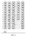
- the OFDM modulation carriers have been distributed into three groups. It can also be seen that the carriers of the first group (24) are not consecutive in frequency.
- a pseudo-differential injection mode is used in a first group (24), and no extra signal processing is used.
- the second group (25) it simultaneously injects in differential and pseudo-differential mode and no extra signal processing is used either, the isolation provided by the injection between the orthogonal modes being sufficient for separating the signals at reception.
- the carriers of the third group (26) it simultaneously injects in differential and pseudo-differential mode, and techniques for MIMO are applied.
- the different carriers are assigned to each of the groups (24), (25) or (26) based on the characteristics of the channel in the frequency of each carrier or based on other application-dependent criteria.
Landscapes
- Engineering & Computer Science (AREA)
- Signal Processing (AREA)
- Computer Networks & Wireless Communication (AREA)
- Power Engineering (AREA)
- Cable Transmission Systems, Equalization Of Radio And Reduction Of Echo (AREA)
- Radio Transmission System (AREA)
Applications Claiming Priority (2)
| Application Number | Priority Date | Filing Date | Title |
|---|---|---|---|
| ES200702256A ES2334190B1 (es) | 2007-08-09 | 2007-08-09 | Procedimiento para aumentar las prestaciones de un sistema de comunicaciones sobre un medio formado por multiples conductores. |
| PCT/ES2008/000496 WO2009022040A1 (fr) | 2007-08-09 | 2008-07-14 | Procédé pour augmenter les performances d'un système de communications sur un support formé de multiples conducteurs |
Publications (3)
| Publication Number | Publication Date |
|---|---|
| EP2200184A1 true EP2200184A1 (fr) | 2010-06-23 |
| EP2200184A4 EP2200184A4 (fr) | 2014-07-30 |
| EP2200184B1 EP2200184B1 (fr) | 2017-09-20 |
Family
ID=40350420
Family Applications (1)
| Application Number | Title | Priority Date | Filing Date |
|---|---|---|---|
| EP08805326.9A Active EP2200184B1 (fr) | 2007-08-09 | 2008-07-14 | Procédé pour augmenter les performances d'un système de communications sur un support formé de multiples conducteurs |
Country Status (9)
| Country | Link |
|---|---|
| US (2) | US8587159B2 (fr) |
| EP (1) | EP2200184B1 (fr) |
| JP (1) | JP5339218B2 (fr) |
| KR (1) | KR101531359B1 (fr) |
| CN (1) | CN101821958B (fr) |
| ES (1) | ES2334190B1 (fr) |
| IL (1) | IL203848A (fr) |
| TW (1) | TWI478518B (fr) |
| WO (1) | WO2009022040A1 (fr) |
Cited By (1)
| Publication number | Priority date | Publication date | Assignee | Title |
|---|---|---|---|---|
| WO2015088717A1 (fr) * | 2013-12-12 | 2015-06-18 | Qualcomm Incorporated | Réutilisation de canal de réseau voisin par des stations à capacité mimo |
Families Citing this family (11)
| Publication number | Priority date | Publication date | Assignee | Title |
|---|---|---|---|---|
| JP3154335B2 (ja) | 1991-08-13 | 2001-04-09 | ソニー株式会社 | 画質制御装置 |
| US10141984B2 (en) | 2008-07-14 | 2018-11-27 | Marvell World Trade Ltd. | Multi-band transmission system |
| EP2909951B1 (fr) | 2012-10-12 | 2021-12-01 | Sony Group Corporation | Dispositif de communications et procédé d'émission d'au moins deux signaux d'émission parallèles |
| US9350315B1 (en) * | 2013-08-06 | 2016-05-24 | Marvell International Ltd. | Power line communication filter for multiple conductors |
| US9865783B2 (en) | 2013-09-09 | 2018-01-09 | Luminus, Inc. | Distributed Bragg reflector on an aluminum package for an LED |
| WO2016128048A1 (fr) * | 2015-02-12 | 2016-08-18 | Huawei Technologies Co., Ltd. | Radio full duplex dotée d'une réduction adaptative de la puissance de réception |
| US11116072B2 (en) * | 2017-07-05 | 2021-09-07 | Intel Corporation | Discrete circuit having cross-talk noise cancellation circuitry and method thereof |
| US11166222B2 (en) * | 2019-08-02 | 2021-11-02 | AR & NS Investment, LLC | Communication by a repeater system including a network of radio frequency (RF) repeater devices |
| EP4313356A4 (fr) | 2021-04-16 | 2025-02-19 | Repligen Corporation | Système et procédé de filtration |
| US11880320B1 (en) * | 2021-06-18 | 2024-01-23 | Peraton Labs Inc. | Common-mode signaling and coupler bypass in legacy busses |
| EP4374497A2 (fr) * | 2021-07-22 | 2024-05-29 | Continental Automotive Technologies GmbH | Procédé d'estimation d'informations de canal et de détection d'activité d'utilisateur conjointes dans des systèmes mimo extra-large (xl-mimo) avec des non stationnarités |
Family Cites Families (9)
| Publication number | Priority date | Publication date | Assignee | Title |
|---|---|---|---|---|
| NO893068L (no) * | 1988-07-29 | 1990-01-30 | Shell Int Research | Fremgangsmaate for modulaer transmisjon og innretning for flerlederkabler. |
| US5412689A (en) * | 1992-12-23 | 1995-05-02 | International Business Machines Corporation | Modal propagation of information through a defined transmission medium |
| US5553097A (en) * | 1994-06-01 | 1996-09-03 | International Business Machines Corporation | System and method for transporting high-bandwidth signals over electrically conducting transmission lines |
| US6226330B1 (en) * | 1998-07-16 | 2001-05-01 | Silicon Graphics, Inc. | Eigen-mode encoding of signals in a data group |
| DE60135067D1 (de) | 2000-06-28 | 2008-09-11 | Agere Syst Guardian Corp | Induktive Kopplung für Silizium-Datenzugriffsanordnung |
| FR2852168B1 (fr) * | 2003-03-06 | 2005-04-29 | Excem | Procede et dispositif numeriques pour la transmission avec une faible diaphonie |
| CN1286277C (zh) * | 2003-11-20 | 2006-11-22 | 中兴通讯股份有限公司 | 网络处理器中核心处理器与微引擎之间的通信方法 |
| US20060187971A1 (en) | 2005-02-18 | 2006-08-24 | Lum Richard K K | Method and apparatus for concurrently transmitting a digital control signal and an analog signal from a sending circuit to a receiving circuit |
| US7773497B2 (en) | 2005-05-09 | 2010-08-10 | Adaptive Spectrum And Signal Alignment, Inc. | Phantom use in DSL systems |
-
2007
- 2007-08-09 ES ES200702256A patent/ES2334190B1/es not_active Expired - Fee Related
-
2008
- 2008-07-14 JP JP2010519480A patent/JP5339218B2/ja not_active Expired - Fee Related
- 2008-07-14 US US12/672,863 patent/US8587159B2/en not_active Expired - Fee Related
- 2008-07-14 EP EP08805326.9A patent/EP2200184B1/fr active Active
- 2008-07-14 KR KR1020107003989A patent/KR101531359B1/ko not_active Expired - Fee Related
- 2008-07-14 WO PCT/ES2008/000496 patent/WO2009022040A1/fr not_active Ceased
- 2008-07-14 CN CN200880111462.3A patent/CN101821958B/zh active Active
- 2008-08-08 TW TW097130399A patent/TWI478518B/zh not_active IP Right Cessation
-
2010
- 2010-02-09 IL IL203848A patent/IL203848A/en not_active IP Right Cessation
-
2013
- 2013-11-19 US US14/083,737 patent/US8957550B2/en active Active
Cited By (2)
| Publication number | Priority date | Publication date | Assignee | Title |
|---|---|---|---|---|
| WO2015088717A1 (fr) * | 2013-12-12 | 2015-06-18 | Qualcomm Incorporated | Réutilisation de canal de réseau voisin par des stations à capacité mimo |
| US9137004B2 (en) | 2013-12-12 | 2015-09-15 | Qualcomm Incorporated | Neighbor network channel reuse with MIMO capable stations |
Also Published As
| Publication number | Publication date |
|---|---|
| CN101821958A (zh) | 2010-09-01 |
| TWI478518B (zh) | 2015-03-21 |
| US20110293024A1 (en) | 2011-12-01 |
| ES2334190B1 (es) | 2011-01-17 |
| JP5339218B2 (ja) | 2013-11-13 |
| KR101531359B1 (ko) | 2015-06-24 |
| EP2200184B1 (fr) | 2017-09-20 |
| US20140079143A1 (en) | 2014-03-20 |
| ES2334190A1 (es) | 2010-03-05 |
| US8587159B2 (en) | 2013-11-19 |
| CN101821958B (zh) | 2013-04-24 |
| JP2010536218A (ja) | 2010-11-25 |
| IL203848A (en) | 2015-05-31 |
| EP2200184A4 (fr) | 2014-07-30 |
| WO2009022040A8 (fr) | 2009-06-04 |
| US8957550B2 (en) | 2015-02-17 |
| TW200924408A (en) | 2009-06-01 |
| KR20100042286A (ko) | 2010-04-23 |
| WO2009022040A1 (fr) | 2009-02-19 |
Similar Documents
| Publication | Publication Date | Title |
|---|---|---|
| US8587159B2 (en) | Method for increasing the performance of a communications system on a medium formed by multiple conductors | |
| Bolcskei et al. | Capacity scaling laws in MIMO relay networks | |
| KR101081317B1 (ko) | 릴레이 기반의 df 협력 무선 네트워크에서 분산형 μιμο 채널 프리코딩 및 디코딩 방법 | |
| Hammerstroem et al. | Space-time processing for cooperative relay networks | |
| US20210234636A1 (en) | Multiple stream space-time block coding | |
| Chandrasekhar et al. | Performance evaluation of MIMO-NOMA for the next generation wireless communications | |
| Lemayian et al. | Hybrid MIMO: a new transmission method for simultaneously achieving spatial multiplexing and diversity gains in MIMO systems | |
| KR101356936B1 (ko) | 폐루프 다중 입력 다중 출력 통신시스템에서 채널 분해 방법 및 장치 | |
| Hassan | Multi user MIMO‐OFDM‐based power line communication structure with hardware impairments and crosstalk | |
| CN100557988C (zh) | 降低频率复用率的无线通信系统 | |
| KR101063892B1 (ko) | 반이중 방식 릴레이 시스템, 이에 있어서 협력 통신 방법 및 수신기에서 신호 처리 방법 | |
| Iqbal et al. | A new MIMO technique utilizing superimposed auxiliary signals for simultaneously achieving spatial multiplexing and diversity gains in MIMO-aided communication systems | |
| Sun et al. | Channel training and estimation in distributed space-time coded relay networks with multiple transmit/receive antennas | |
| Jing et al. | Beamforming in wireless relay networks | |
| Grishma et al. | Performance analysis of 5G waveforms for MIMO System | |
| Degenhardt et al. | A network coding approach to non-regenerative multi-antenna multi-group multi-way relaying | |
| Anitha et al. | MIMO system performance using various modulations under different channels with STBC, ZF and MRC | |
| Sheremet et al. | Software-Defined Radio Wireless Communication Technology Design. LTE MIMO Mode Validation | |
| EP1336268B1 (fr) | Procede et mecanisme de transmission de signaux numeriques | |
| Jing et al. | Interference cancellation in distributed space-time coded wireless relay networks | |
| de Almeida et al. | A trilinear decompositiond approach fof space-time-frequency multiple-access wireless systems | |
| Chan et al. | Reverse signal-aligned network coding in interference channels with limited transmitter cooperation | |
| Naqvi et al. | On hybrid front-haul for 5G NR mmWave indoor coverage | |
| EP1796285B1 (fr) | Transmission de signaux codés d'espace-temps pour communication sans fil | |
| Hanafi et al. | Performance of MIMO and Relay Communication System using TGn and HH Channel |
Legal Events
| Date | Code | Title | Description |
|---|---|---|---|
| PUAI | Public reference made under article 153(3) epc to a published international application that has entered the european phase |
Free format text: ORIGINAL CODE: 0009012 |
|
| 17P | Request for examination filed |
Effective date: 20100309 |
|
| AK | Designated contracting states |
Kind code of ref document: A1 Designated state(s): AT BE BG CH CY CZ DE DK EE ES FI FR GB GR HR HU IE IS IT LI LT LU LV MC MT NL NO PL PT RO SE SI SK TR |
|
| AX | Request for extension of the european patent |
Extension state: AL BA MK RS |
|
| DAX | Request for extension of the european patent (deleted) | ||
| RAP1 | Party data changed (applicant data changed or rights of an application transferred) |
Owner name: MARVELL HISPANIA S.L. |
|
| A4 | Supplementary search report drawn up and despatched |
Effective date: 20140626 |
|
| RIC1 | Information provided on ipc code assigned before grant |
Ipc: H04J 13/00 20110101ALN20140620BHEP Ipc: H04L 25/02 20060101ALI20140620BHEP Ipc: H04B 3/32 20060101ALI20140620BHEP Ipc: H04L 5/14 20060101ALI20140620BHEP Ipc: H04L 5/00 20060101ALI20140620BHEP Ipc: H04B 3/54 20060101AFI20140620BHEP Ipc: H04L 5/20 20060101ALI20140620BHEP Ipc: H04L 23/02 20060101ALI20140620BHEP |
|
| 17Q | First examination report despatched |
Effective date: 20160329 |
|
| REG | Reference to a national code |
Ref country code: DE Ref legal event code: R079 Ref document number: 602008052198 Country of ref document: DE Free format text: PREVIOUS MAIN CLASS: H04B0003000000 Ipc: H04B0003540000 |
|
| GRAP | Despatch of communication of intention to grant a patent |
Free format text: ORIGINAL CODE: EPIDOSNIGR1 |
|
| STAA | Information on the status of an ep patent application or granted ep patent |
Free format text: STATUS: GRANT OF PATENT IS INTENDED |
|
| RIC1 | Information provided on ipc code assigned before grant |
Ipc: H04L 5/00 20060101ALI20170317BHEP Ipc: H04J 13/00 20110101ALN20170317BHEP Ipc: H04L 5/14 20060101ALI20170317BHEP Ipc: H04L 23/02 20060101ALI20170317BHEP Ipc: H04B 3/54 20060101AFI20170317BHEP Ipc: H04B 3/32 20060101ALI20170317BHEP Ipc: H04L 25/02 20060101ALI20170317BHEP Ipc: H04L 5/20 20060101ALI20170317BHEP |
|
| INTG | Intention to grant announced |
Effective date: 20170406 |
|
| GRAS | Grant fee paid |
Free format text: ORIGINAL CODE: EPIDOSNIGR3 |
|
| GRAA | (expected) grant |
Free format text: ORIGINAL CODE: 0009210 |
|
| STAA | Information on the status of an ep patent application or granted ep patent |
Free format text: STATUS: THE PATENT HAS BEEN GRANTED |
|
| AK | Designated contracting states |
Kind code of ref document: B1 Designated state(s): AT BE BG CH CY CZ DE DK EE ES FI FR GB GR HR HU IE IS IT LI LT LU LV MC MT NL NO PL PT RO SE SI SK TR |
|
| REG | Reference to a national code |
Ref country code: GB Ref legal event code: FG4D |
|
| REG | Reference to a national code |
Ref country code: CH Ref legal event code: EP |
|
| REG | Reference to a national code |
Ref country code: AT Ref legal event code: REF Ref document number: 930861 Country of ref document: AT Kind code of ref document: T Effective date: 20171015 |
|
| REG | Reference to a national code |
Ref country code: IE Ref legal event code: FG4D |
|
| REG | Reference to a national code |
Ref country code: DE Ref legal event code: R096 Ref document number: 602008052198 Country of ref document: DE |
|
| REG | Reference to a national code |
Ref country code: NL Ref legal event code: MP Effective date: 20170920 |
|
| PG25 | Lapsed in a contracting state [announced via postgrant information from national office to epo] |
Ref country code: FI Free format text: LAPSE BECAUSE OF FAILURE TO SUBMIT A TRANSLATION OF THE DESCRIPTION OR TO PAY THE FEE WITHIN THE PRESCRIBED TIME-LIMIT Effective date: 20170920 Ref country code: SE Free format text: LAPSE BECAUSE OF FAILURE TO SUBMIT A TRANSLATION OF THE DESCRIPTION OR TO PAY THE FEE WITHIN THE PRESCRIBED TIME-LIMIT Effective date: 20170920 Ref country code: HR Free format text: LAPSE BECAUSE OF FAILURE TO SUBMIT A TRANSLATION OF THE DESCRIPTION OR TO PAY THE FEE WITHIN THE PRESCRIBED TIME-LIMIT Effective date: 20170920 Ref country code: NO Free format text: LAPSE BECAUSE OF FAILURE TO SUBMIT A TRANSLATION OF THE DESCRIPTION OR TO PAY THE FEE WITHIN THE PRESCRIBED TIME-LIMIT Effective date: 20171220 Ref country code: LT Free format text: LAPSE BECAUSE OF FAILURE TO SUBMIT A TRANSLATION OF THE DESCRIPTION OR TO PAY THE FEE WITHIN THE PRESCRIBED TIME-LIMIT Effective date: 20170920 |
|
| REG | Reference to a national code |
Ref country code: LT Ref legal event code: MG4D |
|
| REG | Reference to a national code |
Ref country code: AT Ref legal event code: MK05 Ref document number: 930861 Country of ref document: AT Kind code of ref document: T Effective date: 20170920 |
|
| PG25 | Lapsed in a contracting state [announced via postgrant information from national office to epo] |
Ref country code: BG Free format text: LAPSE BECAUSE OF FAILURE TO SUBMIT A TRANSLATION OF THE DESCRIPTION OR TO PAY THE FEE WITHIN THE PRESCRIBED TIME-LIMIT Effective date: 20171220 Ref country code: LV Free format text: LAPSE BECAUSE OF FAILURE TO SUBMIT A TRANSLATION OF THE DESCRIPTION OR TO PAY THE FEE WITHIN THE PRESCRIBED TIME-LIMIT Effective date: 20170920 |
|
| PG25 | Lapsed in a contracting state [announced via postgrant information from national office to epo] |
Ref country code: NL Free format text: LAPSE BECAUSE OF FAILURE TO SUBMIT A TRANSLATION OF THE DESCRIPTION OR TO PAY THE FEE WITHIN THE PRESCRIBED TIME-LIMIT Effective date: 20170920 |
|
| PG25 | Lapsed in a contracting state [announced via postgrant information from national office to epo] |
Ref country code: RO Free format text: LAPSE BECAUSE OF FAILURE TO SUBMIT A TRANSLATION OF THE DESCRIPTION OR TO PAY THE FEE WITHIN THE PRESCRIBED TIME-LIMIT Effective date: 20170920 Ref country code: CZ Free format text: LAPSE BECAUSE OF FAILURE TO SUBMIT A TRANSLATION OF THE DESCRIPTION OR TO PAY THE FEE WITHIN THE PRESCRIBED TIME-LIMIT Effective date: 20170920 Ref country code: ES Free format text: LAPSE BECAUSE OF FAILURE TO SUBMIT A TRANSLATION OF THE DESCRIPTION OR TO PAY THE FEE WITHIN THE PRESCRIBED TIME-LIMIT Effective date: 20170920 Ref country code: PL Free format text: LAPSE BECAUSE OF FAILURE TO SUBMIT A TRANSLATION OF THE DESCRIPTION OR TO PAY THE FEE WITHIN THE PRESCRIBED TIME-LIMIT Effective date: 20170920 |
|
| PG25 | Lapsed in a contracting state [announced via postgrant information from national office to epo] |
Ref country code: IS Free format text: LAPSE BECAUSE OF FAILURE TO SUBMIT A TRANSLATION OF THE DESCRIPTION OR TO PAY THE FEE WITHIN THE PRESCRIBED TIME-LIMIT Effective date: 20180120 Ref country code: EE Free format text: LAPSE BECAUSE OF FAILURE TO SUBMIT A TRANSLATION OF THE DESCRIPTION OR TO PAY THE FEE WITHIN THE PRESCRIBED TIME-LIMIT Effective date: 20170920 Ref country code: IT Free format text: LAPSE BECAUSE OF FAILURE TO SUBMIT A TRANSLATION OF THE DESCRIPTION OR TO PAY THE FEE WITHIN THE PRESCRIBED TIME-LIMIT Effective date: 20170920 Ref country code: SK Free format text: LAPSE BECAUSE OF FAILURE TO SUBMIT A TRANSLATION OF THE DESCRIPTION OR TO PAY THE FEE WITHIN THE PRESCRIBED TIME-LIMIT Effective date: 20170920 Ref country code: AT Free format text: LAPSE BECAUSE OF FAILURE TO SUBMIT A TRANSLATION OF THE DESCRIPTION OR TO PAY THE FEE WITHIN THE PRESCRIBED TIME-LIMIT Effective date: 20170920 |
|
| REG | Reference to a national code |
Ref country code: DE Ref legal event code: R097 Ref document number: 602008052198 Country of ref document: DE |
|
| PLBE | No opposition filed within time limit |
Free format text: ORIGINAL CODE: 0009261 |
|
| STAA | Information on the status of an ep patent application or granted ep patent |
Free format text: STATUS: NO OPPOSITION FILED WITHIN TIME LIMIT |
|
| PG25 | Lapsed in a contracting state [announced via postgrant information from national office to epo] |
Ref country code: DK Free format text: LAPSE BECAUSE OF FAILURE TO SUBMIT A TRANSLATION OF THE DESCRIPTION OR TO PAY THE FEE WITHIN THE PRESCRIBED TIME-LIMIT Effective date: 20170920 |
|
| 26N | No opposition filed |
Effective date: 20180621 |
|
| PG25 | Lapsed in a contracting state [announced via postgrant information from national office to epo] |
Ref country code: SI Free format text: LAPSE BECAUSE OF FAILURE TO SUBMIT A TRANSLATION OF THE DESCRIPTION OR TO PAY THE FEE WITHIN THE PRESCRIBED TIME-LIMIT Effective date: 20170920 |
|
| REG | Reference to a national code |
Ref country code: CH Ref legal event code: PL |
|
| GBPC | Gb: european patent ceased through non-payment of renewal fee |
Effective date: 20180714 |
|
| PG25 | Lapsed in a contracting state [announced via postgrant information from national office to epo] |
Ref country code: MC Free format text: LAPSE BECAUSE OF FAILURE TO SUBMIT A TRANSLATION OF THE DESCRIPTION OR TO PAY THE FEE WITHIN THE PRESCRIBED TIME-LIMIT Effective date: 20170920 Ref country code: LU Free format text: LAPSE BECAUSE OF NON-PAYMENT OF DUE FEES Effective date: 20180714 |
|
| REG | Reference to a national code |
Ref country code: BE Ref legal event code: MM Effective date: 20180731 |
|
| REG | Reference to a national code |
Ref country code: IE Ref legal event code: MM4A |
|
| PG25 | Lapsed in a contracting state [announced via postgrant information from national office to epo] |
Ref country code: LI Free format text: LAPSE BECAUSE OF NON-PAYMENT OF DUE FEES Effective date: 20180731 Ref country code: FR Free format text: LAPSE BECAUSE OF NON-PAYMENT OF DUE FEES Effective date: 20180731 Ref country code: CH Free format text: LAPSE BECAUSE OF NON-PAYMENT OF DUE FEES Effective date: 20180731 Ref country code: IE Free format text: LAPSE BECAUSE OF NON-PAYMENT OF DUE FEES Effective date: 20180714 Ref country code: GB Free format text: LAPSE BECAUSE OF NON-PAYMENT OF DUE FEES Effective date: 20180714 |
|
| PG25 | Lapsed in a contracting state [announced via postgrant information from national office to epo] |
Ref country code: BE Free format text: LAPSE BECAUSE OF NON-PAYMENT OF DUE FEES Effective date: 20180731 |
|
| PG25 | Lapsed in a contracting state [announced via postgrant information from national office to epo] |
Ref country code: MT Free format text: LAPSE BECAUSE OF NON-PAYMENT OF DUE FEES Effective date: 20180714 |
|
| PG25 | Lapsed in a contracting state [announced via postgrant information from national office to epo] |
Ref country code: TR Free format text: LAPSE BECAUSE OF FAILURE TO SUBMIT A TRANSLATION OF THE DESCRIPTION OR TO PAY THE FEE WITHIN THE PRESCRIBED TIME-LIMIT Effective date: 20170920 |
|
| PG25 | Lapsed in a contracting state [announced via postgrant information from national office to epo] |
Ref country code: PT Free format text: LAPSE BECAUSE OF FAILURE TO SUBMIT A TRANSLATION OF THE DESCRIPTION OR TO PAY THE FEE WITHIN THE PRESCRIBED TIME-LIMIT Effective date: 20170920 Ref country code: HU Free format text: LAPSE BECAUSE OF FAILURE TO SUBMIT A TRANSLATION OF THE DESCRIPTION OR TO PAY THE FEE WITHIN THE PRESCRIBED TIME-LIMIT; INVALID AB INITIO Effective date: 20080714 |
|
| PG25 | Lapsed in a contracting state [announced via postgrant information from national office to epo] |
Ref country code: CY Free format text: LAPSE BECAUSE OF FAILURE TO SUBMIT A TRANSLATION OF THE DESCRIPTION OR TO PAY THE FEE WITHIN THE PRESCRIBED TIME-LIMIT Effective date: 20170920 Ref country code: GR Free format text: LAPSE BECAUSE OF FAILURE TO SUBMIT A TRANSLATION OF THE DESCRIPTION OR TO PAY THE FEE WITHIN THE PRESCRIBED TIME-LIMIT Effective date: 20170920 |
|
| PGFP | Annual fee paid to national office [announced via postgrant information from national office to epo] |
Ref country code: DE Payment date: 20250729 Year of fee payment: 18 |