EP2200244A1 - Procédé et appareil de transmission de multiplexage de division de fréquence multiporteuse - Google Patents
Procédé et appareil de transmission de multiplexage de division de fréquence multiporteuse Download PDFInfo
- Publication number
- EP2200244A1 EP2200244A1 EP09179629A EP09179629A EP2200244A1 EP 2200244 A1 EP2200244 A1 EP 2200244A1 EP 09179629 A EP09179629 A EP 09179629A EP 09179629 A EP09179629 A EP 09179629A EP 2200244 A1 EP2200244 A1 EP 2200244A1
- Authority
- EP
- European Patent Office
- Prior art keywords
- frequency
- digital
- carrier
- signal
- transmit
- Prior art date
- Legal status (The legal status is an assumption and is not a legal conclusion. Google has not performed a legal analysis and makes no representation as to the accuracy of the status listed.)
- Granted
Links
Images


Classifications
-
- H—ELECTRICITY
- H04—ELECTRIC COMMUNICATION TECHNIQUE
- H04J—MULTIPLEX COMMUNICATION
- H04J11/00—Orthogonal multiplex systems, e.g. using WALSH codes
- H04J11/0023—Interference mitigation or co-ordination
-
- H—ELECTRICITY
- H04—ELECTRIC COMMUNICATION TECHNIQUE
- H04L—TRANSMISSION OF DIGITAL INFORMATION, e.g. TELEGRAPHIC COMMUNICATION
- H04L5/00—Arrangements affording multiple use of the transmission path
- H04L5/003—Arrangements for allocating sub-channels of the transmission path
-
- H—ELECTRICITY
- H04—ELECTRIC COMMUNICATION TECHNIQUE
- H04L—TRANSMISSION OF DIGITAL INFORMATION, e.g. TELEGRAPHIC COMMUNICATION
- H04L27/00—Modulated-carrier systems
- H04L27/0006—Assessment of spectral gaps suitable for allocating digitally modulated signals, e.g. for carrier allocation in cognitive radio
-
- H—ELECTRICITY
- H04—ELECTRIC COMMUNICATION TECHNIQUE
- H04L—TRANSMISSION OF DIGITAL INFORMATION, e.g. TELEGRAPHIC COMMUNICATION
- H04L27/00—Modulated-carrier systems
- H04L27/26—Systems using multi-frequency codes
- H04L27/2601—Multicarrier modulation systems
- H04L27/2602—Signal structure
- H04L27/2605—Symbol extensions, e.g. Zero Tail, Unique Word [UW]
- H04L27/2607—Cyclic extensions
-
- H—ELECTRICITY
- H04—ELECTRIC COMMUNICATION TECHNIQUE
- H04L—TRANSMISSION OF DIGITAL INFORMATION, e.g. TELEGRAPHIC COMMUNICATION
- H04L27/00—Modulated-carrier systems
- H04L27/26—Systems using multi-frequency codes
- H04L27/2601—Multicarrier modulation systems
- H04L27/2626—Arrangements specific to the transmitter only
- H04L27/2627—Modulators
- H04L27/2637—Modulators with direct modulation of individual subcarriers
-
- H—ELECTRICITY
- H04—ELECTRIC COMMUNICATION TECHNIQUE
- H04L—TRANSMISSION OF DIGITAL INFORMATION, e.g. TELEGRAPHIC COMMUNICATION
- H04L27/00—Modulated-carrier systems
- H04L27/26—Systems using multi-frequency codes
- H04L27/2601—Multicarrier modulation systems
- H04L27/2647—Arrangements specific to the receiver only
- H04L27/2649—Demodulators
- H04L27/2653—Demodulators with direct demodulation of individual subcarriers
-
- H—ELECTRICITY
- H04—ELECTRIC COMMUNICATION TECHNIQUE
- H04L—TRANSMISSION OF DIGITAL INFORMATION, e.g. TELEGRAPHIC COMMUNICATION
- H04L5/00—Arrangements affording multiple use of the transmission path
- H04L5/0001—Arrangements for dividing the transmission path
- H04L5/0003—Two-dimensional division
- H04L5/0005—Time-frequency
- H04L5/0007—Time-frequency the frequencies being orthogonal, e.g. OFDM(A) or DMT
-
- H—ELECTRICITY
- H04—ELECTRIC COMMUNICATION TECHNIQUE
- H04L—TRANSMISSION OF DIGITAL INFORMATION, e.g. TELEGRAPHIC COMMUNICATION
- H04L5/00—Arrangements affording multiple use of the transmission path
- H04L5/02—Channels characterised by the type of signal
- H04L5/06—Channels characterised by the type of signal the signals being represented by different frequencies
-
- H—ELECTRICITY
- H04—ELECTRIC COMMUNICATION TECHNIQUE
- H04J—MULTIPLEX COMMUNICATION
- H04J11/00—Orthogonal multiplex systems, e.g. using WALSH codes
- H04J2011/0003—Combination with other multiplexing techniques
- H04J2011/0009—Combination with other multiplexing techniques with FDM/FDMA
-
- H—ELECTRICITY
- H04—ELECTRIC COMMUNICATION TECHNIQUE
- H04L—TRANSMISSION OF DIGITAL INFORMATION, e.g. TELEGRAPHIC COMMUNICATION
- H04L27/00—Modulated-carrier systems
- H04L27/26—Systems using multi-frequency codes
- H04L27/2601—Multicarrier modulation systems
- H04L27/2614—Peak power aspects
Definitions
- the present invention relates to a method for data transmission employing a frequency division multiplexing technique and a corresponding apparatus for multi-carrier frequency division multiplexing transmission.
- TV white spaces are not consecutively placed in the spectrum; rather, the UHF TV spectrum exhibits a strong spectrum fragmentation.
- a system is required which can cope with strong spectrum fragmentation and which is able to perform aggregation of several TVWS by one single wideband signal.
- Another example for a radio spectrum that may exhibit unused spaces is in low power sensor networks.
- the design of a transceiver architecture and concept, allowing to opportunistically exploit white spaces of allocated radio frequency bands for wireless data communications is particularly difficult, mainly for two reasons.
- signal generation should ensure ultra-low out-off-band radiation to strictly avoid harmful interference to legacy TV signals.
- the receivers and/or transmitters should exhibit high sensitivity in order to explore white spaces, i.e., to sense even very weak radio signals in allocated frequency bands.
- a method for data transmission by frequency division multiplexing according to claim 1.
- the invention further provides a corresponding transmitter arrangement and a receiver arrangement.
- the inventive approach exhibits some attractive features which are of particular importance for scenarios exhibiting high degrees of spectrum fragmentation.
- the generalized digital multi-carrier transmitter concept according to the invention provides a lower peak-to-average power ratio (PAPR) compared to OFDM, a ultra-low out-of-band radiation due to adjustable Tx-filtering, and last but not least a block-based transmission using cyclic prefix insertion and efficient FFT-based equalization.
- PAPR peak-to-average power ratio
- the novel transmission concept of the invention enables frequency and time domain multi-user scheduling comparable to OFDM and provides an efficient alternative for white space aggregation even in heavily fragmented spectrum regions. Unlike in OFDM, the FDM carriers are no longer necessarily orthogonal to each other.
- GFDM Generalized Frequency Division Multiplexing
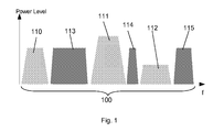
- Fig. 1 illustrates a frequency range 100, which in one embodiment may be the UHF frequency range traditionally used for the transmission of television signals 110 - 112. These TV signals may occupy an individual bandwidth and may be of individual signal power as indicated by the height of the signal blocks. As illustrated, the TV signals 110 - 112 are not bordering each other, thus leaving vacant frequency ranges 113 - 115 between the TV signals. These vacant frequency ranges 113 - 115 are also called TV white spaces (TVWS) in the following.
- TVWS TV white spaces
- TV white spaces 113 - 115 may be used for the transmission of arbitrary signals, wherein the arbitrary signals must not interfere with adjacent signals, i.e. the arbitrary signals transmitted in the TV white spaces must not leak into adjacent frequency bands used for other, e.g. TV, signals. Accordingly the signals transmitted must exhibit a low out-off-band radiation to avoid harmful interference to legacy signals of adjacent frequency bands.
- the transmitter or the receiver or both may scan potential frequency ranges.
- Vacant frequency ranges can be detected for example by investigating the energy transmitted on a frequency. Note that the transmitter and/or receiver scans the potential frequency ranges very carefully in order to detect even weak signals and in order to prevent any interference with detected signals.
- the transmitter or the receiver determines the vacant frequency ranges to be used for subsequent transmission.
- the transmitter and the receiver both may scan potential frequency ranges and may then coordinate the search for vacant frequencies to ensure that frequencies are used, which have been detected as vacant by both the transmitter and the sender.
- the bandwidth and the center frequency of frequency range are determined by either the transmitter or the receiver or in cooperation. Since a single carrier transmission method will be used, the center frequency of the determined vacant frequency range determines the carrier frequency and the bandwidth limits the baud rate of the transmission.
- the receiver informs the transmitter about possible center frequencies and available bandwidths.
- the transmitter informs the receiver about details for the following signal transmission accordingly. That is, the transmitter informs the receiver about all the details necessary for transmitting data, i.e. the modulation type, the baud rate, coding mode etc. to be used for the following transmission.
- an established communication channel between the transmitter and the receiver is assumed, which can be used for transmitting the determined detail information of the subsequent transmission from the receiver to the transmitter and back.
- Said established communication channel in one embodiment may be a signaling channel for distributing information to a plurality of receivers.
- the transmission using the detected vacant frequency range stops if at least one of the following criteria is matched.
- the transmitter may listen on the used frequency range for unexpected signals, which indicate that there is another transmitter using the frequency range.
- the transmitter may comprise corresponding means for listening.
- the transmitter may inform the receiver correspondingly about the detected interference using above mentioned established communication channel.
- the transmitter may stop the transmission on the detected frequency range, if the receiver indicates that it cannot receive, i.e.decode, the transmitted signals successfully, which may due to interfering signals at the receiver.
- the receiver may indicate to stop the transmission of signals on the vacant frequency range for example directly by a signal sent on the above mentioned established communication channel or by not sending an acknowledge message in the vacant frequency range.
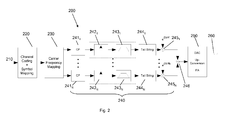
- Fig. 2 shows a schematic block diagram of an embodiment of a digital transmitter 200 capable of transmitting an incoming stream 210 of information bits using at least one or a plurality of detected TV white spaces simultaneously.
- Processing block 220 performs channel encoding on the incoming stream of information thus producing a stream of channel encoded bits.
- the channel encoding may comprise, for example, the removal of redundant information or may comprise the addition of error correcting information, for example a cyclic redundancy check (CRC) code.
- CRC cyclic redundancy check
- the stream of encoded bits is then mapped to transmit symbols, thus producing a stream of transmit symbols representing the stream of channel encoded information bits, wherein said symbols may be QAM or alternatively QPSK symbols.
- the stream of transmit symbols is passed to processing block 230, which maps the symbols to at least one or a plurality of N carrier frequencies, wherein the n carrier frequencies are center frequencies of vacant frequency bands.
- processing block 230 maps the symbols to at least one or a plurality of N carrier frequencies, wherein the n carrier frequencies are center frequencies of vacant frequency bands.
- n corresponds to the number of detected vacant frequencies.
- Each of the symbols is then passed to one of a plurality of N parallel processing branches 240. Since each of the branches comprises the same processing blocks, the following description relates to all branches.
- Each branch comprises a processing block 241 n for adding a cyclic prefix (CP) to each symbol, an up-sampling block 242 n and a digital filter 243 n for pulse shaping each symbol, processing block 244 n for performing a tail-biting technique and a complex multiplier 245 n for digitally frequency shifting a symbol relative to the at least one other carrier frequency of another used parallel branch.
- CP cyclic prefix
- Every carrier is modulated individually, using some arbitrary form of modulation.
- the QAM symbol stream on carrier n is denoted as s ( n,k ), where k represents the symbol index.
- the symbol's index now turns into the sample index k ', representing the sample duration T S .
- cyclic prefix (CP) insertion is performed, accounting for the filter length of the digital pulse shaping, the filter length of the digital receive filter and the length of the mobile channel impulse response.
- CP cyclic prefix
- digital pulse shaping is performed in blocks 242 n , 243 n carrier-wise, wherein each symbol is up-sampled in block 242 n and each up-sampled symbol s ( n,k ') of the n-th carrier is convoluted with the transmit filter function of the n-th branch g Tx ( n,k' ) : s n ⁇ k ⁇ * g Tx n ⁇ k ⁇
- a signal produced by one branch is hence defined in the interval [-1/2 : 1/2] centered around the carrier frequency.
- the digital time domain signals of all used branches are then combined by a complex adder 246 to form a single digital signal representing the combination of all digital time domain signals, which is passed to block 250.
- each time domain signal x ( k ') is digital-to-analogue converted, mixed to the carrier frequency and amplified to form one transmit signal.
- the resulting single transmit signal is a wideband transmit signal. Said wideband transmit signal is transmitted via antenna 260.
- the used carriers may not be orthogonal to each other. Rather, each carrier is modulated individually thus forming a single carrier transmission using cyclic prefixing. Accordingly, i.e. if at least two or more vacant frequency ranges are detected and used, the wideband signal as transmitted by antenna 260 comprises a plurality of single carrier signals each using cyclic prefixing.
- OFDM uses a cyclic prefix (CP) to simplify signal equalization but on the other side exhibits a high peak-to-average power ratio (PAPR) as one major drawback.
- PAPR peak-to-average power ratio
- SC-CP single carrier with cyclic prefix
- the resulting transmit signal exhibits the following properties.
- Each carrier represents an independent SC-CP link, which can be modulated individually having an own bandwidth and pulse shaping.
- the frequency division multiplexed (FDM) carriers are not orthogonal but exhibit mutual interference which can be adjusted by the individual transmit (Tx) filters and signal bandwidths.
- the GFDM concept combines the advantages of the simple equalization with the ability of flexible allocation of white spaces, i.e. vacant frequency bands, and controllable out-off-band radiation. Furthermore the transmitter architecture allows an easy equalization despite the wideband nature of the transmit signal, a frequency agile white space allocation and flexible signal bandwidth. Due to the digital implementation of each branch 240, the requirements of the analogue front-end are reduced.
- Transmit signal 300 consists of payload samples, i.e. portion 310, and samples of a cyclic prefix 320, wherein conventional cyclic prefix samples are the last samples of the payload copied to the beginning of the signal to produce a symmetric signal.
- the length of cyclic prefix is determined by the properties of the transmit filter, the transmit channel and the receive filter as schematically indicated by portions 330 - 350.
- the first portion 330 reflecting the length of the transmit (Tx) filter is neglected, thus shortening the length of the cyclic prefix as depicted in Fig. 3B .
- Fig. 3C depicts the signal after having passed the transmit filter processing block 243 n , which appends some digital samples 350 to the signal.
- the samples 360 appended by the transmit filter processing are cut off and superimposed to the first samples of the shortened cyclic prefix 320, thus emulating a circular convolution to assimilate the beginning of the signal block to its end.
- Fig. 4 depicts a preferred embodiment of a receiver 400 according to the concept of the invention, which performs parallel single-carrier cyclic-prefix (SC-CP) demodulation for each of the carriers.
- SC-CP single-carrier cyclic-prefix
- Receiver 400 comprises an antenna 410 for receiving an incoming radio signal, an analog input stage 420 and a plurality of N parallel digital processing paths 430 coupled to the output of input stage 420, a carrier de-mapping block 440 coupled to the output each of the N parallel processing paths and a decoder block 450 outputting a stream of information bits 460, which ideally are those as input to a corresponding transmitter.
- the signal as received by antenna 410 i.e. the receive signal
- antenna 410 is passed from antenna 410 to the analog input stage 420, which amplifies the receive signal typically by using a low noise amplifier (LNA), and down-converts the amplified receive signal to a frequency suitable as input to a digital-to-analog converter comprised in stage 420.
- LNA low noise amplifier
- the amplified and down-converted receive signal is analogue-to-digital converted thus yielding a digitized receive signal y ( k' ).
- the receive signal is then coupled to n of the N parallel digital processing paths 430, wherein n is the number of used carrier frequencies. Since all of the N parallel digital processing paths 430 comprise the same functionality, the following description relates to each. In each of the n paths the receive signal is mixed to an individual carrier frequency f n , individually in each of the n used parallel branches by deploying a complex multiplication in multiplier 431 n .
- the receive filtering is used to cancel out the undesired adjacent channel interference.
- a high selectivity i.e. steep filter edges, will provide low inter channel interference (ICI) and therefore a higher signal to noise ratio (SNR).
- SNR signal to noise ratio
- sharp filter edges typically require high filter orders, which in turn have to be compensated for by an appropriate cyclic prefix length which in turn decreases the system's spectral efficiency.
- processing block 434 n the cyclic prefix is removed and the signal z ( n,k ') is transformed into the time domain using FFT processing block 435 n in order to yield the frequency bins Z ( n,l ) of the n-th carrier signal.
- processing block 440 for de-mapping the symbols from the n carriers, thus producing a stream of digital symbols, which ideally reflect the stream of digital symbols as output by processing block 230 in the transmitter.
- the stream of digital symbols as output by de-mapper block 440 is fed into the detector/decoder stage 450, which outputs a stream of bits 460.
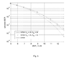
- bit error rate (BER) performance of the proposed system is compared with the corresponding bit error rate of an OFDM system.
- the aim of this evaluation is to show the impact of the non-orthogonal GFDM carriers which can be controlled by the selectivity of the Tx and Rx digital system filters.
- both the OFDM and the GFDM system are designed to have the same spectral efficiency, i.e., both system parameter sets are defined according to Table I.
- a cyclic prefix (CP) overhead of 25% for both the GFDM and the OFDM system.
- OFDM inherently exhibits this overhead due to the cyclic prefix in each OFDM symbol.
- the cyclic prefix depends on the length of the receive (Rx-) filter, where the length of the mobile channel can be neglected due to the AWGN assumption.
- the GFDM FFT block length is 100 symbols.
- the GFDM FFT is 6.25 times longer than in the OFDM system.
- Fig.5 depicts the bit error rate of uncoded QPSK modulated symbols for both OFDM and GFDM, where GFDM uses different filter orders for transmit (Tx) and receive (Rx) filtering.
- Tx transmit
- Rx receive
- the orders of the digital Tx and Rx cosine roll-off filters are denoted by O Tx and O Rx , respectively.
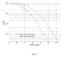
- Fig.6 shows a comparison of the peak-to-average power ratio (PAPR) for OFDM and GFDM. Due to fewer carriers, GFDM exhibits a superior peak-to-average power ratio (PAPR) performance compared to conventional OFDM signaling.
- PAPR peak-to-average power ratio
Landscapes
- Engineering & Computer Science (AREA)
- Signal Processing (AREA)
- Computer Networks & Wireless Communication (AREA)
- Physics & Mathematics (AREA)
- Health & Medical Sciences (AREA)
- General Health & Medical Sciences (AREA)
- Spectroscopy & Molecular Physics (AREA)
- Transmitters (AREA)
- Cable Transmission Systems, Equalization Of Radio And Reduction Of Echo (AREA)
Priority Applications (1)
| Application Number | Priority Date | Filing Date | Title |
|---|---|---|---|
| EP09179629.2A EP2200244B1 (fr) | 2008-12-18 | 2009-12-17 | Procédé et appareil de transmission de multiplexage de division de fréquence multiporteuse |
Applications Claiming Priority (2)
| Application Number | Priority Date | Filing Date | Title |
|---|---|---|---|
| EP08022010 | 2008-12-18 | ||
| EP09179629.2A EP2200244B1 (fr) | 2008-12-18 | 2009-12-17 | Procédé et appareil de transmission de multiplexage de division de fréquence multiporteuse |
Publications (2)
| Publication Number | Publication Date |
|---|---|
| EP2200244A1 true EP2200244A1 (fr) | 2010-06-23 |
| EP2200244B1 EP2200244B1 (fr) | 2019-02-20 |
Family
ID=42026378
Family Applications (1)
| Application Number | Title | Priority Date | Filing Date |
|---|---|---|---|
| EP09179629.2A Active EP2200244B1 (fr) | 2008-12-18 | 2009-12-17 | Procédé et appareil de transmission de multiplexage de division de fréquence multiporteuse |
Country Status (2)
| Country | Link |
|---|---|
| US (2) | US8929352B2 (fr) |
| EP (1) | EP2200244B1 (fr) |
Cited By (8)
| Publication number | Priority date | Publication date | Assignee | Title |
|---|---|---|---|---|
| WO2012145553A1 (fr) * | 2011-04-20 | 2012-10-26 | Qualcomm Incorporated | Capteur de spectre radio cognitif utilisant un rapport valeur de crête sur valeur moyenne en tant que caractéristique du signal |
| EP2916506A1 (fr) * | 2014-03-07 | 2015-09-09 | Vodafone GmbH | Transmission radio GFDM transformée de Walsh-Hadamard |
| EP2978183A1 (fr) * | 2014-07-21 | 2016-01-27 | Cassidian Finland OY | Filtrage d'un signal modulé |
| JP2016134854A (ja) * | 2015-01-21 | 2016-07-25 | 株式会社国際電気通信基礎技術研究所 | 無線通信装置および無線通信システム |
| JP2016154296A (ja) * | 2015-02-20 | 2016-08-25 | 株式会社国際電気通信基礎技術研究所 | 無線通信装置、無線モジュールおよびそれらを備える無線通信システム |
| WO2016148362A1 (fr) * | 2015-03-19 | 2016-09-22 | 엘지전자 주식회사 | Procédé d'attribution de ressources pour la prise en charge d'une pluralité de modes de communication sans fil dans un système de communication sans fil, et son dispositif |
| US11239931B2 (en) | 2018-07-03 | 2022-02-01 | Istanbul Teknik Universitesi | Generalized frequency division multiplexing method with multiple-input multiple-output and flexible index modulation |
| US20250211470A1 (en) * | 2023-12-21 | 2025-06-26 | Quasistatics Inc. | Method and system for pulse shaping of baseband signals in communication networks using electroquasisatic signals |
Families Citing this family (20)
| Publication number | Priority date | Publication date | Assignee | Title |
|---|---|---|---|---|
| US20130198582A1 (en) * | 2012-01-30 | 2013-08-01 | Broadcom Corporation | Supercharged codes |
| CN104823402B (zh) * | 2012-11-29 | 2017-07-28 | Idac控股公司 | 一种用于在无线通信设备内执行多载波调制的方法 |
| US10009209B2 (en) | 2013-03-28 | 2018-06-26 | Huawei Technologies Co., Ltd. | System and method for generalized multi-carrier frequency division multiplexing |
| US9635508B2 (en) * | 2014-01-14 | 2017-04-25 | The United States Of America As Represented By The Secretary Of The Army | Fast method for wideband spectrum sensing |
| US10701685B2 (en) * | 2014-03-31 | 2020-06-30 | Huawei Technologies Co., Ltd. | Method and apparatus for asynchronous OFDMA/SC-FDMA |
| KR20160052070A (ko) * | 2014-11-04 | 2016-05-12 | 삼성전자주식회사 | 비직교 송신 신호를 사용하는 다중 반송파 시스템에서 신호를 송수신하는 방법 및 장치 |
| US10601620B2 (en) | 2015-09-04 | 2020-03-24 | National Taiwan University | Device of handling block transmission in multicarrier system |
| EP3358765B1 (fr) | 2015-10-01 | 2022-03-09 | Sony Group Corporation | Dispositif, procédé et programme |
| US10938608B2 (en) | 2015-11-19 | 2021-03-02 | Sony Corporation | Apparatus and method |
| WO2017126897A1 (fr) * | 2016-01-19 | 2017-07-27 | 연세대학교 산학협력단 | Procédé et appareil de transmission pour accès multiple dans un système de communications sans fil |
| KR101958074B1 (ko) | 2016-01-19 | 2019-03-14 | 연세대학교 산학협력단 | 무선 통신 시스템에서 다중 접속 방법 및 다중 접속을 위한 전송 장치 |
| CN108476191B (zh) * | 2016-01-21 | 2021-05-07 | 索尼公司 | 装置、方法和介质 |
| MX2018009485A (es) | 2016-02-12 | 2018-09-06 | Sony Corp | Aparato y metodo. |
| WO2017197270A1 (fr) * | 2016-05-13 | 2017-11-16 | Battelle Energy Alliance, Llc | Systèmes, dispositifs et procédés de communication de données sur des formes d'ondes en forme d'impulsions circulaires |
| CN109937546B (zh) * | 2016-11-09 | 2022-06-07 | 瑞典爱立信有限公司 | 用于同时的ofdma信令和非ofdma信令的链路自适应 |
| WO2019136526A1 (fr) * | 2018-01-12 | 2019-07-18 | University Of Technology Sydney | Système et procédé de transmission double à formation d'impulsions |
| WO2020084336A1 (fr) * | 2018-10-26 | 2020-04-30 | Telefonaktiebolaget Lm Ericsson (Publ) | Systèmes et procédés de pré-codage multi-porteuse ou multi-bande de faible papr qui gèrent un préfixe cyclique |
| US10574503B1 (en) | 2018-12-28 | 2020-02-25 | Hughes Network Systems, Llc | Efficient cyclic prefix generation with half tone offset |
| US11239882B2 (en) * | 2019-02-12 | 2022-02-01 | DecaWave, Ltd. | Method and apparatus for increasing bit rates in 4z |
| CN113014519A (zh) * | 2021-03-05 | 2021-06-22 | 杭州电子科技大学 | 一种在双脉冲成型发射系统中避免频谱零点的方法 |
Citations (2)
| Publication number | Priority date | Publication date | Assignee | Title |
|---|---|---|---|---|
| WO2005099131A2 (fr) | 2004-03-26 | 2005-10-20 | Pulse-Link, Inc. | Systemes et procedes de transmission de donnees au sein d'un reseau de communication sans fil |
| WO2007052995A1 (fr) | 2005-11-07 | 2007-05-10 | Electronics And Telecommunications Research Institute | Procede permettant d'utiliser une largeur de bande souple dans un systeme radio cognitif a acces multiple par repartition orthogonale de la frequence (ofdma), station de base et station d'abonne utilisant un tel procede |
Family Cites Families (11)
| Publication number | Priority date | Publication date | Assignee | Title |
|---|---|---|---|---|
| US7110349B2 (en) * | 2001-03-06 | 2006-09-19 | Brn Phoenix, Inc. | Adaptive communications methods for multiple user packet radio wireless networks |
| US8045935B2 (en) * | 2001-12-06 | 2011-10-25 | Pulse-Link, Inc. | High data rate transmitter and receiver |
| US7697641B2 (en) * | 2004-06-28 | 2010-04-13 | L-3 Communications | Parallel DSP demodulation for wideband software-defined radios |
| US7747666B2 (en) * | 2004-08-09 | 2010-06-29 | L-3 Communications Corporation | Parallel filter realization for wideband programmable digital radios |
| US8484272B2 (en) * | 2004-08-20 | 2013-07-09 | Qualcomm Incorporated | Unified pulse shaping for multi-carrier and single-carrier waveforms |
| US7808886B2 (en) * | 2006-01-18 | 2010-10-05 | Freescale Semiconductor, Inc. | Pilot signal in an FDMA communication system |
| US9538388B2 (en) * | 2006-05-12 | 2017-01-03 | Shared Spectrum Company | Method and system for dynamic spectrum access |
| EP1936900A1 (fr) * | 2006-12-18 | 2008-06-25 | Nokia Siemens Networks Gmbh & Co. Kg | Procédé et dispositif OFDM destinés à la transmission de données SC-FDMA |
| EP2173045A1 (fr) * | 2007-06-28 | 2010-04-07 | Panasonic Corporation | Emetteur, procédé d'émission, récepteur et procédé de réception |
| EP2091194B1 (fr) * | 2008-02-12 | 2014-06-25 | Telefonaktiebolaget L M Ericsson (PUBL) | Technique d'accès multiple à division de fréquence avec porteuse unique |
| US8064329B2 (en) * | 2008-06-19 | 2011-11-22 | Freescale Semiconductor, Inc. | Control and data information communication in a wireless system |
-
2009
- 2009-12-17 US US12/640,428 patent/US8929352B2/en active Active
- 2009-12-17 EP EP09179629.2A patent/EP2200244B1/fr active Active
-
2015
- 2015-01-05 US US14/589,290 patent/US20150188654A1/en not_active Abandoned
Patent Citations (2)
| Publication number | Priority date | Publication date | Assignee | Title |
|---|---|---|---|---|
| WO2005099131A2 (fr) | 2004-03-26 | 2005-10-20 | Pulse-Link, Inc. | Systemes et procedes de transmission de donnees au sein d'un reseau de communication sans fil |
| WO2007052995A1 (fr) | 2005-11-07 | 2007-05-10 | Electronics And Telecommunications Research Institute | Procede permettant d'utiliser une largeur de bande souple dans un systeme radio cognitif a acces multiple par repartition orthogonale de la frequence (ofdma), station de base et station d'abonne utilisant un tel procede |
Non-Patent Citations (1)
| Title |
|---|
| FETTWEIS G ET AL: "GFDM - Generalized Frequency Division Multiplexing", 2009 IEEE 69TH VEHICULAR TECHNOLOGY CONFERENCE; APRIL 26-29, 2009, BARCELONA, SPAIN, IEEE, PISCATAWAY, NJ, USA, 26 April 2009 (2009-04-26), pages 1 - 4, XP031474518, ISBN: 978-1-4244-2517-4 * |
Cited By (12)
| Publication number | Priority date | Publication date | Assignee | Title |
|---|---|---|---|---|
| WO2012145553A1 (fr) * | 2011-04-20 | 2012-10-26 | Qualcomm Incorporated | Capteur de spectre radio cognitif utilisant un rapport valeur de crête sur valeur moyenne en tant que caractéristique du signal |
| US8594121B2 (en) | 2011-04-20 | 2013-11-26 | Qualcomm Incorporated | Cognitive radio spectrum sensor employing peak-to-average ratio as the signal feature |
| EP2916506A1 (fr) * | 2014-03-07 | 2015-09-09 | Vodafone GmbH | Transmission radio GFDM transformée de Walsh-Hadamard |
| US9680540B2 (en) | 2014-03-07 | 2017-06-13 | Vodafone Gmbh | Walsh-hadamard transformed GFDM radio transmission |
| EP2978183A1 (fr) * | 2014-07-21 | 2016-01-27 | Cassidian Finland OY | Filtrage d'un signal modulé |
| WO2016012428A1 (fr) * | 2014-07-21 | 2016-01-28 | Cassidian Finland Oy | Filtrage d'un signal modulé |
| JP2016134854A (ja) * | 2015-01-21 | 2016-07-25 | 株式会社国際電気通信基礎技術研究所 | 無線通信装置および無線通信システム |
| JP2016154296A (ja) * | 2015-02-20 | 2016-08-25 | 株式会社国際電気通信基礎技術研究所 | 無線通信装置、無線モジュールおよびそれらを備える無線通信システム |
| WO2016148362A1 (fr) * | 2015-03-19 | 2016-09-22 | 엘지전자 주식회사 | Procédé d'attribution de ressources pour la prise en charge d'une pluralité de modes de communication sans fil dans un système de communication sans fil, et son dispositif |
| US10454634B2 (en) | 2015-03-19 | 2019-10-22 | Lg Electronics Inc. | Method for allocating resources for supporting plurality of wireless communication modes in wireless communication system, and device for same |
| US11239931B2 (en) | 2018-07-03 | 2022-02-01 | Istanbul Teknik Universitesi | Generalized frequency division multiplexing method with multiple-input multiple-output and flexible index modulation |
| US20250211470A1 (en) * | 2023-12-21 | 2025-06-26 | Quasistatics Inc. | Method and system for pulse shaping of baseband signals in communication networks using electroquasisatic signals |
Also Published As
| Publication number | Publication date |
|---|---|
| US20100189132A1 (en) | 2010-07-29 |
| EP2200244B1 (fr) | 2019-02-20 |
| US20150188654A1 (en) | 2015-07-02 |
| US8929352B2 (en) | 2015-01-06 |
Similar Documents
| Publication | Publication Date | Title |
|---|---|---|
| EP2200244B1 (fr) | Procédé et appareil de transmission de multiplexage de division de fréquence multiporteuse | |
| US8867587B2 (en) | Double-layer multi-carrier ultra-wideband wireless communication method | |
| Fettweis et al. | GFDM-generalized frequency division multiplexing | |
| EP2504940B1 (fr) | Communications de données sans fil | |
| US10348544B2 (en) | Method and device for controlling power in multi-carrier communication system | |
| CN100521563C (zh) | 用于交织频分多址通信系统中的跳频的方法和装置 | |
| Datta et al. | GFDM interference cancellation for flexible cognitive radio PHY design | |
| US7675982B2 (en) | Method and system for reducing peak-to-average power for OFDM signals | |
| US6510133B1 (en) | Multi-carrier transmission method and data transmitter | |
| US7583738B2 (en) | Apparatus and method for reducing peak-to-average power ratio in orthogonal frequency division multiplexing communication system | |
| CN101682592B (zh) | 用于sc-fdma数据传输的方法以及ofdm装置 | |
| EP2033393B1 (fr) | Multiplexage orthogonal à repartition fréquentielle utilisant le traitement de sous-symboles | |
| US20100111138A1 (en) | Versatile System for Dual Carrier Transformation in Orthogonal Frequency Division Multiplexing | |
| EP1662737B1 (fr) | Procédé et dispositif permettant de réduire le rapport entre la puissance de crête et la puissance moyenne dans un système de communication à porteuses multiples | |
| CN113454919B (zh) | 一种卫星通信系统 | |
| US20100002571A1 (en) | Methods for transceiving data in multi-band orthogonal frequency division multiple access communications system and communications apparatuses utilizing the same | |
| CN102075483A (zh) | 降低ofdm信号峰均比的方法 | |
| CN1720687B (zh) | 用于使用正交频分复用调制通信超宽带宽信号的方法和发射机 | |
| US20190349157A1 (en) | Receiver, transmitter, communication system for subband communication and methods for subband communication | |
| US20080137716A1 (en) | Digital frequency hopping in multi-band OFDM | |
| CN1885844B (zh) | 基于正交复用多载波传输降低峰均比的装置及其方法 | |
| Lakshmanan et al. | Maximally frequency selective wavelet packets based multi-carrier modulation scheme for cognitive radio systems | |
| CN106413006A (zh) | 一种均匀子带叠加的ofdm通信方法及系统 | |
| CN109768823B (zh) | 一种窄带多通道卫星通信系统 | |
| Hossain et al. | Waveform design and nonlinear sensitivity analysis of WR-OCDM system for B5G wireless communications |
Legal Events
| Date | Code | Title | Description |
|---|---|---|---|
| PUAI | Public reference made under article 153(3) epc to a published international application that has entered the european phase |
Free format text: ORIGINAL CODE: 0009012 |
|
| AK | Designated contracting states |
Kind code of ref document: A1 Designated state(s): AT BE BG CH CY CZ DE DK EE ES FI FR GB GR HR HU IE IS IT LI LT LU LV MC MK MT NL NO PL PT RO SE SI SK SM TR |
|
| AX | Request for extension of the european patent |
Extension state: AL BA RS |
|
| 17P | Request for examination filed |
Effective date: 20101222 |
|
| 17Q | First examination report despatched |
Effective date: 20131125 |
|
| GRAP | Despatch of communication of intention to grant a patent |
Free format text: ORIGINAL CODE: EPIDOSNIGR1 |
|
| STAA | Information on the status of an ep patent application or granted ep patent |
Free format text: STATUS: GRANT OF PATENT IS INTENDED |
|
| INTG | Intention to grant announced |
Effective date: 20180903 |
|
| RIN1 | Information on inventor provided before grant (corrected) |
Inventor name: FETTWEIS, GERHARD Inventor name: KRONDORF, MARCO Inventor name: BITTNER, STEFFEN |
|
| GRAS | Grant fee paid |
Free format text: ORIGINAL CODE: EPIDOSNIGR3 |
|
| RIN1 | Information on inventor provided before grant (corrected) |
Inventor name: BITTNER, STEFFEN Inventor name: FETTWEIS, GERHARD Inventor name: KRONDORF, MARCO |
|
| GRAA | (expected) grant |
Free format text: ORIGINAL CODE: 0009210 |
|
| STAA | Information on the status of an ep patent application or granted ep patent |
Free format text: STATUS: THE PATENT HAS BEEN GRANTED |
|
| AK | Designated contracting states |
Kind code of ref document: B1 Designated state(s): AT BE BG CH CY CZ DE DK EE ES FI FR GB GR HR HU IE IS IT LI LT LU LV MC MK MT NL NO PL PT RO SE SI SK SM TR |
|
| REG | Reference to a national code |
Ref country code: GB Ref legal event code: FG4D |
|
| REG | Reference to a national code |
Ref country code: CH Ref legal event code: EP |
|
| REG | Reference to a national code |
Ref country code: DE Ref legal event code: R096 Ref document number: 602009057035 Country of ref document: DE |
|
| REG | Reference to a national code |
Ref country code: AT Ref legal event code: REF Ref document number: 1099695 Country of ref document: AT Kind code of ref document: T Effective date: 20190315 |
|
| REG | Reference to a national code |
Ref country code: IE Ref legal event code: FG4D |
|
| REG | Reference to a national code |
Ref country code: LT Ref legal event code: MG4D |
|
| REG | Reference to a national code |
Ref country code: NL Ref legal event code: MP Effective date: 20190220 |
|
| PG25 | Lapsed in a contracting state [announced via postgrant information from national office to epo] |
Ref country code: LT Free format text: LAPSE BECAUSE OF FAILURE TO SUBMIT A TRANSLATION OF THE DESCRIPTION OR TO PAY THE FEE WITHIN THE PRESCRIBED TIME-LIMIT Effective date: 20190220 Ref country code: FI Free format text: LAPSE BECAUSE OF FAILURE TO SUBMIT A TRANSLATION OF THE DESCRIPTION OR TO PAY THE FEE WITHIN THE PRESCRIBED TIME-LIMIT Effective date: 20190220 Ref country code: NO Free format text: LAPSE BECAUSE OF FAILURE TO SUBMIT A TRANSLATION OF THE DESCRIPTION OR TO PAY THE FEE WITHIN THE PRESCRIBED TIME-LIMIT Effective date: 20190520 Ref country code: PT Free format text: LAPSE BECAUSE OF FAILURE TO SUBMIT A TRANSLATION OF THE DESCRIPTION OR TO PAY THE FEE WITHIN THE PRESCRIBED TIME-LIMIT Effective date: 20190620 Ref country code: SE Free format text: LAPSE BECAUSE OF FAILURE TO SUBMIT A TRANSLATION OF THE DESCRIPTION OR TO PAY THE FEE WITHIN THE PRESCRIBED TIME-LIMIT Effective date: 20190220 |
|
| PG25 | Lapsed in a contracting state [announced via postgrant information from national office to epo] |
Ref country code: HR Free format text: LAPSE BECAUSE OF FAILURE TO SUBMIT A TRANSLATION OF THE DESCRIPTION OR TO PAY THE FEE WITHIN THE PRESCRIBED TIME-LIMIT Effective date: 20190220 Ref country code: LV Free format text: LAPSE BECAUSE OF FAILURE TO SUBMIT A TRANSLATION OF THE DESCRIPTION OR TO PAY THE FEE WITHIN THE PRESCRIBED TIME-LIMIT Effective date: 20190220 Ref country code: GR Free format text: LAPSE BECAUSE OF FAILURE TO SUBMIT A TRANSLATION OF THE DESCRIPTION OR TO PAY THE FEE WITHIN THE PRESCRIBED TIME-LIMIT Effective date: 20190521 Ref country code: IS Free format text: LAPSE BECAUSE OF FAILURE TO SUBMIT A TRANSLATION OF THE DESCRIPTION OR TO PAY THE FEE WITHIN THE PRESCRIBED TIME-LIMIT Effective date: 20190620 Ref country code: BG Free format text: LAPSE BECAUSE OF FAILURE TO SUBMIT A TRANSLATION OF THE DESCRIPTION OR TO PAY THE FEE WITHIN THE PRESCRIBED TIME-LIMIT Effective date: 20190520 Ref country code: NL Free format text: LAPSE BECAUSE OF FAILURE TO SUBMIT A TRANSLATION OF THE DESCRIPTION OR TO PAY THE FEE WITHIN THE PRESCRIBED TIME-LIMIT Effective date: 20190220 |
|
| REG | Reference to a national code |
Ref country code: AT Ref legal event code: MK05 Ref document number: 1099695 Country of ref document: AT Kind code of ref document: T Effective date: 20190220 |
|
| PG25 | Lapsed in a contracting state [announced via postgrant information from national office to epo] |
Ref country code: SK Free format text: LAPSE BECAUSE OF FAILURE TO SUBMIT A TRANSLATION OF THE DESCRIPTION OR TO PAY THE FEE WITHIN THE PRESCRIBED TIME-LIMIT Effective date: 20190220 Ref country code: EE Free format text: LAPSE BECAUSE OF FAILURE TO SUBMIT A TRANSLATION OF THE DESCRIPTION OR TO PAY THE FEE WITHIN THE PRESCRIBED TIME-LIMIT Effective date: 20190220 Ref country code: CZ Free format text: LAPSE BECAUSE OF FAILURE TO SUBMIT A TRANSLATION OF THE DESCRIPTION OR TO PAY THE FEE WITHIN THE PRESCRIBED TIME-LIMIT Effective date: 20190220 Ref country code: RO Free format text: LAPSE BECAUSE OF FAILURE TO SUBMIT A TRANSLATION OF THE DESCRIPTION OR TO PAY THE FEE WITHIN THE PRESCRIBED TIME-LIMIT Effective date: 20190220 Ref country code: ES Free format text: LAPSE BECAUSE OF FAILURE TO SUBMIT A TRANSLATION OF THE DESCRIPTION OR TO PAY THE FEE WITHIN THE PRESCRIBED TIME-LIMIT Effective date: 20190220 Ref country code: DK Free format text: LAPSE BECAUSE OF FAILURE TO SUBMIT A TRANSLATION OF THE DESCRIPTION OR TO PAY THE FEE WITHIN THE PRESCRIBED TIME-LIMIT Effective date: 20190220 Ref country code: IT Free format text: LAPSE BECAUSE OF FAILURE TO SUBMIT A TRANSLATION OF THE DESCRIPTION OR TO PAY THE FEE WITHIN THE PRESCRIBED TIME-LIMIT Effective date: 20190220 |
|
| REG | Reference to a national code |
Ref country code: DE Ref legal event code: R097 Ref document number: 602009057035 Country of ref document: DE |
|
| PG25 | Lapsed in a contracting state [announced via postgrant information from national office to epo] |
Ref country code: PL Free format text: LAPSE BECAUSE OF FAILURE TO SUBMIT A TRANSLATION OF THE DESCRIPTION OR TO PAY THE FEE WITHIN THE PRESCRIBED TIME-LIMIT Effective date: 20190220 Ref country code: SM Free format text: LAPSE BECAUSE OF FAILURE TO SUBMIT A TRANSLATION OF THE DESCRIPTION OR TO PAY THE FEE WITHIN THE PRESCRIBED TIME-LIMIT Effective date: 20190220 |
|
| PLBE | No opposition filed within time limit |
Free format text: ORIGINAL CODE: 0009261 |
|
| STAA | Information on the status of an ep patent application or granted ep patent |
Free format text: STATUS: NO OPPOSITION FILED WITHIN TIME LIMIT |
|
| PG25 | Lapsed in a contracting state [announced via postgrant information from national office to epo] |
Ref country code: AT Free format text: LAPSE BECAUSE OF FAILURE TO SUBMIT A TRANSLATION OF THE DESCRIPTION OR TO PAY THE FEE WITHIN THE PRESCRIBED TIME-LIMIT Effective date: 20190220 |
|
| 26N | No opposition filed |
Effective date: 20191121 |
|
| PG25 | Lapsed in a contracting state [announced via postgrant information from national office to epo] |
Ref country code: SI Free format text: LAPSE BECAUSE OF FAILURE TO SUBMIT A TRANSLATION OF THE DESCRIPTION OR TO PAY THE FEE WITHIN THE PRESCRIBED TIME-LIMIT Effective date: 20190220 |
|
| PG25 | Lapsed in a contracting state [announced via postgrant information from national office to epo] |
Ref country code: TR Free format text: LAPSE BECAUSE OF FAILURE TO SUBMIT A TRANSLATION OF THE DESCRIPTION OR TO PAY THE FEE WITHIN THE PRESCRIBED TIME-LIMIT Effective date: 20190220 |
|
| REG | Reference to a national code |
Ref country code: CH Ref legal event code: PL |
|
| REG | Reference to a national code |
Ref country code: BE Ref legal event code: MM Effective date: 20191231 |
|
| PG25 | Lapsed in a contracting state [announced via postgrant information from national office to epo] |
Ref country code: MC Free format text: LAPSE BECAUSE OF FAILURE TO SUBMIT A TRANSLATION OF THE DESCRIPTION OR TO PAY THE FEE WITHIN THE PRESCRIBED TIME-LIMIT Effective date: 20190220 |
|
| PG25 | Lapsed in a contracting state [announced via postgrant information from national office to epo] |
Ref country code: LU Free format text: LAPSE BECAUSE OF NON-PAYMENT OF DUE FEES Effective date: 20191217 Ref country code: IE Free format text: LAPSE BECAUSE OF NON-PAYMENT OF DUE FEES Effective date: 20191217 |
|
| PG25 | Lapsed in a contracting state [announced via postgrant information from national office to epo] |
Ref country code: LI Free format text: LAPSE BECAUSE OF NON-PAYMENT OF DUE FEES Effective date: 20191231 Ref country code: CH Free format text: LAPSE BECAUSE OF NON-PAYMENT OF DUE FEES Effective date: 20191231 Ref country code: BE Free format text: LAPSE BECAUSE OF NON-PAYMENT OF DUE FEES Effective date: 20191231 |
|
| PG25 | Lapsed in a contracting state [announced via postgrant information from national office to epo] |
Ref country code: CY Free format text: LAPSE BECAUSE OF FAILURE TO SUBMIT A TRANSLATION OF THE DESCRIPTION OR TO PAY THE FEE WITHIN THE PRESCRIBED TIME-LIMIT Effective date: 20190220 |
|
| PG25 | Lapsed in a contracting state [announced via postgrant information from national office to epo] |
Ref country code: HU Free format text: LAPSE BECAUSE OF FAILURE TO SUBMIT A TRANSLATION OF THE DESCRIPTION OR TO PAY THE FEE WITHIN THE PRESCRIBED TIME-LIMIT; INVALID AB INITIO Effective date: 20091217 Ref country code: MT Free format text: LAPSE BECAUSE OF FAILURE TO SUBMIT A TRANSLATION OF THE DESCRIPTION OR TO PAY THE FEE WITHIN THE PRESCRIBED TIME-LIMIT Effective date: 20190220 |
|
| PG25 | Lapsed in a contracting state [announced via postgrant information from national office to epo] |
Ref country code: MK Free format text: LAPSE BECAUSE OF FAILURE TO SUBMIT A TRANSLATION OF THE DESCRIPTION OR TO PAY THE FEE WITHIN THE PRESCRIBED TIME-LIMIT Effective date: 20190220 |
|
| PGFP | Annual fee paid to national office [announced via postgrant information from national office to epo] |
Ref country code: DE Payment date: 20251211 Year of fee payment: 17 |
|
| PGFP | Annual fee paid to national office [announced via postgrant information from national office to epo] |
Ref country code: GB Payment date: 20251219 Year of fee payment: 17 |
|
| PGFP | Annual fee paid to national office [announced via postgrant information from national office to epo] |
Ref country code: FR Payment date: 20251222 Year of fee payment: 17 |