EP2200387B1 - Contrôle d'accès pour communication cellulaire sans fil - Google Patents
Contrôle d'accès pour communication cellulaire sans fil Download PDFInfo
- Publication number
- EP2200387B1 EP2200387B1 EP09015568A EP09015568A EP2200387B1 EP 2200387 B1 EP2200387 B1 EP 2200387B1 EP 09015568 A EP09015568 A EP 09015568A EP 09015568 A EP09015568 A EP 09015568A EP 2200387 B1 EP2200387 B1 EP 2200387B1
- Authority
- EP
- European Patent Office
- Prior art keywords
- radio resources
- call
- quality
- amount
- control unit
- Prior art date
- Legal status (The legal status is an assumption and is not a legal conclusion. Google has not performed a legal analysis and makes no representation as to the accuracy of the status listed.)
- Not-in-force
Links
- 238000004891 communication Methods 0.000 title claims description 66
- 230000001413 cellular effect Effects 0.000 title description 9
- 238000012545 processing Methods 0.000 description 72
- 230000006835 compression Effects 0.000 description 42
- 238000007906 compression Methods 0.000 description 42
- 230000005540 biological transmission Effects 0.000 description 29
- 238000010586 diagram Methods 0.000 description 27
- 238000000034 method Methods 0.000 description 7
- 230000000903 blocking effect Effects 0.000 description 4
- 230000000694 effects Effects 0.000 description 3
- 230000003044 adaptive effect Effects 0.000 description 2
- 230000001174 ascending effect Effects 0.000 description 2
- 238000007796 conventional method Methods 0.000 description 2
- 230000007774 longterm Effects 0.000 description 2
- 238000005259 measurement Methods 0.000 description 2
- 230000010267 cellular communication Effects 0.000 description 1
- 230000001419 dependent effect Effects 0.000 description 1
- 230000006866 deterioration Effects 0.000 description 1
- 238000011161 development Methods 0.000 description 1
- 230000010354 integration Effects 0.000 description 1
- 238000012986 modification Methods 0.000 description 1
- 230000004048 modification Effects 0.000 description 1
- 238000011160 research Methods 0.000 description 1
Images





Classifications
-
- H—ELECTRICITY
- H04—ELECTRIC COMMUNICATION TECHNIQUE
- H04W—WIRELESS COMMUNICATION NETWORKS
- H04W72/00—Local resource management
- H04W72/50—Allocation or scheduling criteria for wireless resources
- H04W72/54—Allocation or scheduling criteria for wireless resources based on quality criteria
- H04W72/543—Allocation or scheduling criteria for wireless resources based on quality criteria based on requested quality, e.g. QoS
-
- H—ELECTRICITY
- H04—ELECTRIC COMMUNICATION TECHNIQUE
- H04L—TRANSMISSION OF DIGITAL INFORMATION, e.g. TELEGRAPHIC COMMUNICATION
- H04L1/00—Arrangements for detecting or preventing errors in the information received
- H04L1/0001—Systems modifying transmission characteristics according to link quality, e.g. power backoff
- H04L1/0002—Systems modifying transmission characteristics according to link quality, e.g. power backoff by adapting the transmission rate
- H04L1/0003—Systems modifying transmission characteristics according to link quality, e.g. power backoff by adapting the transmission rate by switching between different modulation schemes
-
- H—ELECTRICITY
- H04—ELECTRIC COMMUNICATION TECHNIQUE
- H04L—TRANSMISSION OF DIGITAL INFORMATION, e.g. TELEGRAPHIC COMMUNICATION
- H04L1/00—Arrangements for detecting or preventing errors in the information received
- H04L1/0001—Systems modifying transmission characteristics according to link quality, e.g. power backoff
- H04L1/0006—Systems modifying transmission characteristics according to link quality, e.g. power backoff by adapting the transmission format
- H04L1/0007—Systems modifying transmission characteristics according to link quality, e.g. power backoff by adapting the transmission format by modifying the frame length
-
- H—ELECTRICITY
- H04—ELECTRIC COMMUNICATION TECHNIQUE
- H04L—TRANSMISSION OF DIGITAL INFORMATION, e.g. TELEGRAPHIC COMMUNICATION
- H04L1/00—Arrangements for detecting or preventing errors in the information received
- H04L1/0001—Systems modifying transmission characteristics according to link quality, e.g. power backoff
- H04L1/0009—Systems modifying transmission characteristics according to link quality, e.g. power backoff by adapting the channel coding
-
- H—ELECTRICITY
- H04—ELECTRIC COMMUNICATION TECHNIQUE
- H04L—TRANSMISSION OF DIGITAL INFORMATION, e.g. TELEGRAPHIC COMMUNICATION
- H04L1/00—Arrangements for detecting or preventing errors in the information received
- H04L1/0001—Systems modifying transmission characteristics according to link quality, e.g. power backoff
- H04L1/0015—Systems modifying transmission characteristics according to link quality, e.g. power backoff characterised by the adaptation strategy
- H04L1/0017—Systems modifying transmission characteristics according to link quality, e.g. power backoff characterised by the adaptation strategy where the mode-switching is based on Quality of Service requirement
-
- H—ELECTRICITY
- H04—ELECTRIC COMMUNICATION TECHNIQUE
- H04L—TRANSMISSION OF DIGITAL INFORMATION, e.g. TELEGRAPHIC COMMUNICATION
- H04L27/00—Modulated-carrier systems
- H04L27/0008—Modulated-carrier systems arrangements for allowing a transmitter or receiver to use more than one type of modulation
-
- H—ELECTRICITY
- H04—ELECTRIC COMMUNICATION TECHNIQUE
- H04L—TRANSMISSION OF DIGITAL INFORMATION, e.g. TELEGRAPHIC COMMUNICATION
- H04L27/00—Modulated-carrier systems
- H04L27/32—Carrier systems characterised by combinations of two or more of the types covered by groups H04L27/02, H04L27/10, H04L27/18 or H04L27/26
- H04L27/34—Amplitude- and phase-modulated carrier systems, e.g. quadrature-amplitude modulated carrier systems
- H04L27/36—Modulator circuits; Transmitter circuits
-
- H—ELECTRICITY
- H04—ELECTRIC COMMUNICATION TECHNIQUE
- H04L—TRANSMISSION OF DIGITAL INFORMATION, e.g. TELEGRAPHIC COMMUNICATION
- H04L5/00—Arrangements affording multiple use of the transmission path
- H04L5/0001—Arrangements for dividing the transmission path
- H04L5/0003—Two-dimensional division
- H04L5/0005—Time-frequency
- H04L5/0007—Time-frequency the frequencies being orthogonal, e.g. OFDM(A) or DMT
-
- H—ELECTRICITY
- H04—ELECTRIC COMMUNICATION TECHNIQUE
- H04L—TRANSMISSION OF DIGITAL INFORMATION, e.g. TELEGRAPHIC COMMUNICATION
- H04L5/00—Arrangements affording multiple use of the transmission path
- H04L5/003—Arrangements for allocating sub-channels of the transmission path
- H04L5/0037—Inter-user or inter-terminal allocation
-
- H—ELECTRICITY
- H04—ELECTRIC COMMUNICATION TECHNIQUE
- H04L—TRANSMISSION OF DIGITAL INFORMATION, e.g. TELEGRAPHIC COMMUNICATION
- H04L5/00—Arrangements affording multiple use of the transmission path
- H04L5/003—Arrangements for allocating sub-channels of the transmission path
- H04L5/0058—Allocation criteria
- H04L5/006—Quality of the received signal, e.g. BER, SNR, water filling
-
- H—ELECTRICITY
- H04—ELECTRIC COMMUNICATION TECHNIQUE
- H04L—TRANSMISSION OF DIGITAL INFORMATION, e.g. TELEGRAPHIC COMMUNICATION
- H04L5/00—Arrangements affording multiple use of the transmission path
- H04L5/003—Arrangements for allocating sub-channels of the transmission path
- H04L5/0058—Allocation criteria
- H04L5/0064—Rate requirement of the data, e.g. scalable bandwidth, data priority
-
- H—ELECTRICITY
- H04—ELECTRIC COMMUNICATION TECHNIQUE
- H04L—TRANSMISSION OF DIGITAL INFORMATION, e.g. TELEGRAPHIC COMMUNICATION
- H04L5/00—Arrangements affording multiple use of the transmission path
- H04L5/003—Arrangements for allocating sub-channels of the transmission path
- H04L5/0078—Timing of allocation
- H04L5/0087—Timing of allocation when data requirements change
- H04L5/0089—Timing of allocation when data requirements change due to addition or removal of users or terminals
-
- H—ELECTRICITY
- H04—ELECTRIC COMMUNICATION TECHNIQUE
- H04L—TRANSMISSION OF DIGITAL INFORMATION, e.g. TELEGRAPHIC COMMUNICATION
- H04L5/00—Arrangements affording multiple use of the transmission path
- H04L5/0091—Signalling for the administration of the divided path, e.g. signalling of configuration information
- H04L5/0094—Indication of how sub-channels of the path are allocated
-
- H—ELECTRICITY
- H04—ELECTRIC COMMUNICATION TECHNIQUE
- H04W—WIRELESS COMMUNICATION NETWORKS
- H04W28/00—Network traffic management; Network resource management
- H04W28/16—Central resource management; Negotiation of resources or communication parameters, e.g. negotiating bandwidth or QoS [Quality of Service]
- H04W28/18—Negotiating wireless communication parameters
-
- H—ELECTRICITY
- H04—ELECTRIC COMMUNICATION TECHNIQUE
- H04W—WIRELESS COMMUNICATION NETWORKS
- H04W72/00—Local resource management
- H04W72/50—Allocation or scheduling criteria for wireless resources
- H04W72/56—Allocation or scheduling criteria for wireless resources based on priority criteria
Definitions
- This invention relates to a base station, and more particularly, to a base station capable of access control in wireless communication.
- OFDM orthogonal frequency division multiplexing
- a transmitter that uses OFDM to send a signal generates data to be sent in the frequency domain, converts the generated data into a time domain signal through inverse fast Fourier transform (IFFT), and sends the converted data as a radio signal.
- IFFT inverse fast Fourier transform
- a receiver that uses OFDM to receive a signal obtains the original data by converting the received radio signal of the time domain into a frequency domain signal through fast Fourier transform (FFT).
- FFT fast Fourier transform
- each subcarrier is assigned to a plurality of terminals and multiple access is implemented by multiplexing through OFDM.
- OFDM orthogonal frequency division multiple access
- LTE Long Term Evolution
- UMB Ultra Mobile Broadband
- the LTE or UMB standard uses adaptive modulation.
- adaptive modulation several different Modulation and Coding Schemes (MCSs) telling which modulation scheme and what coding rate for error correcting coding are to be used for packet transmission are defined, and one optimum for the channel state is selected out of the defined schemes. Deciding on an MCS is also a function of the base station.
- MCSs Modulation and Coding Schemes
- the core network of a cellular wireless communication system is at present divided into a circuit switching network for voice communication and a packet switching network for data communication, which are likely to be integrated into a single packet swithcing network by introducing Voice over IP (VoIP), where voice signals are turned into IP packets.
- VoIP Voice over IP
- VoIP Voice over IP
- a delay in the transmission of a voice IP packet does not exceed a certain amount in order to ensure a satisfactory communication quality.
- Future wireless communication systems are also expected to act as a means to deliver various other services than voice communication where the quality of service (QoS) in terms of transmission delay and data transmission rate needs to be guaranteed.
- QoS quality of service
- a first problem to be solved by this invention is wireless link control for guaranteeing QoS in OFDMA.
- EV-DO Evolution Data Optimized
- CDMA code division multiple access
- a second problem to be solved is how a new call of which QoS needs to be guaranteed should be processed in congestion or in a situation close to congestion.
- the base station refuses to accept a new call when the amount of available radio resources is smaller than an amount necessary to guarantee the QoS of the new call (see JP 2002-204481 A , for example).
- the base station terminates an existing call to accept a new call when the new call has a priority higher than that of the existing call (see JP 2004-228905 A , for example).
- a drawback of the above-mentioned two methods is that either a new call or an existing call is blocked.
- This method which changes the data transmission rate of an existing call, may reduce the blocking rate of new calls and existing calls but lowers the QoS of the existing call. Furthermore, changing the data transmission rate requires re-setting the existing call in an upper layer, and the re-setting may increase a processing delay.
- This invention as defined in appended claims 1 and 6 provides a base station and a wireless communication system that are capable of guaranteeing QoS.
- QoS in a wireless system is guaranteed more securely, and the blocking rate of new calls is lowered.
- Fig. 1A and Fig. 1B are diagrams illustrating a principle of radio resources in this invention.
- a cellular wireless communication system that uses OFDMA may freely select the amount of radio resources to be used for a single packet and an MCS (coding rate at which error correcting coding is performed on a packet and modulation scheme to be applied).
- radio resources are frequency and time resources each constituted of a given number of subcarriers and a given number of OFDM symbols.
- An element constituted of one subcarrier and one OFDM symbol represents one modulation symbol.
- One modulation symbol corresponds to one radio resource.
- a white circle and a black circle of Fig. 1A and Fig. 1B represent a data bit and a redundancy bit, respectively.
- a base station assigns to the packet radio resources that are constituted of, in the case of Fig. 1A , two subcarriers and six OFDM symbols.
- the modulation scheme and the coding rate in Fig. 1A are QPSK and 1/3, respectively.
- the base station assigns to the packet radio resources that are constituted of, in the case of Fig. 1B , one subcarrier and six OFDM symbols.
- the modulation scheme and the coding rate in Fig. 1B are 16QAM and 1/3, respectively.
- the radio resource amount used by the packet of Fig. 1B is half the radio resource amount used by the packet of Fig. 1A .
- the number of bits transmitted per modulation symbol in Fig. 1B is twice the number of bits transmitted per modulation symbol in Fig. 1A .
- the number of data bits sent in Fig. 1B is therefore the same as the number of data bits sent in Fig. 1A .
- the packet of Fig. 1B is inferior to the packet of Fig. 1A in terms of error rate at the same received signal-to-noise ratio (SNR).
- SNR signal-to-noise ratio
- a radio environment that sends the packet of Fig. 1B requires a higher received SNR in order to achieve the same error rate as that of the packet of Fig. 1A .
- Figs. 1A and 1B reach the result by varying the modulation scheme.
- the coding rate may be varied instead of the modulation scheme to obtain the same result.
- This invention utilizes this principle to change the radio resource assignment amount without changing the packet size.
- a first embodiment of this invention is described referring to Figs. 2 to 17 .
- Fig. 2 is a configuration diagram of a cellular wireless communication system according to the first embodiment of this invention.
- the cellular wireless communication system generally includes a plurality of base stations and a plurality of terminals as illustrated in Fig. 2 .
- a base station 201a and a base station 201b are each connected via a wired link to a network 203.
- a terminal 202a and a terminal 202b are connected via wireless links to the base station 201a and the base station 201b, respectively, to communicate with the network 203.
- the base station 201a and the base station 201b have the same configuration. Therefore, the base station 201a is discussed as a representative example in the description given below on the base stations.
- wireless links conform to the specifications of Long Term Evolution (LTE).
- LTE Long Term Evolution
- the specifications of wireless links conforming to LTE are defined in detail in TS 36.211 (v8.4.0) standardized by 3GPP (refer to web site of 3GPP http://www.../ftp/Specs/html-info/36211.htm).
- Fig. 3 is a configuration diagram of an LTE radio frame according to the first embodiment of this invention.
- One LTE radio frame has duration of 10 ms, and is divided into ten subframes.
- a packet is sent for every subframe (1 ms).
- a single subframe is further divided into two slots each having a slot time of 0.5 ms.
- Frequency hopping is executed on a slot basis.
- radio resources are assigned with twelve continuous subcarriers as the minimum unit, and two slots that belong to the same subframe are assigned with the same amount of radio resources.
- Fig. 4 is a configuration diagram of an LTE resource block according to the first embodiment of this invention.
- radio resources constituted of one slot of twelve continuous subcarriers are called a resource block (RB).
- a single slot consists of six or seven OFDM symbols.
- the amount of radio resources assigned to each packet transmission is expressed by the number of RBs per slot.
- Fig. 5 is a block diagram illustrating a configuration of a base station according to the first embodiment of this invention.
- the base station 201a includes an antenna 501, an RF processing unit 502, a physical layer processing unit 600, an upper layer processing unit 700, and a network interface 503.
- the RF processing unit 502 is a processing unit that processes radio frequency signals and, for example, has the same configuration as that of an RF processing unit 602 described referring to Fig. 9 of JP 2008-211411 A .
- the physical layer processing unit 600 is a processing unit that processes baseband signals in the physical layer.
- the upper layer processing unit 700 is a processing unit that processes signals in a second layer (data link layer) and layers above the second layer.
- the network interface 503 is an interface that enables the base station 201a to communicate with other devices connected to the network 203.
- Fig. 6 is a block diagram illustrating the physical layer processing unit 600 according to the first embodiment of this invention.
- the physical layer processing unit 600 includes a transmitter 601 and a receiver 602.
- the transmitter 601 performs error correcting coding and modulation on a data packet and control information, which are input from the upper layer processing unit 700, separately, and then maps the two onto physical resources to perform multiplexing.
- the transmitter 601 next generates a downlink baseband signal by performing IFFT calculation on the multiplexed signal, and outputs the generated signal to the RF processing unit 502.
- the coding rate and the modulation scheme that are employed in encoding and modulating the data packet and the physical resource onto which the data packet is mapped are determined according to downlink scheduling information, which is notified from the upper layer processing unit 700.
- the receiver 602 performs FFT calculation on an uplink baseband signal input from the RF processing unit 502, and then demultiplexes the multiplexed signal into a data packet, control information, and a reference signal.
- the data packet and the control information each undergo demodulation and error correcting decoding, and are output to the upper layer processing unit 700.
- the reference signal undergoes received signal power measurement, and the result of the measurement is output to the upper layer processing unit 700 as a piece of control information.
- a physical resource that is referred to when the data packet is demultiplexed from the multiplexed signal and the modulation scheme and the coding rate that are employed in demodulating and decoding the data packet are determined according to uplink scheduling information, which is notified from the upper layer processing unit 700.
- Fig. 7 is a block diagram illustrating the upper layer processing unit 700 according to the first embodiment of this invention.
- the upper layer processing unit 700 includes a transmitter 710, a receiver 720, and a controller 730.
- the transmitter 710 stores in a downlink transmission queue 711 downlink user data, which is received from the network 203 via the network interface 503. From the downlink transmission queue 711, the transmitter 710 reads user data as scheduled by a scheduler 731 to generate a data packet. The transmitter 710 also generates various types of control information including uplink scheduling information and downlink scheduling information. The generated data packet and control information are output to the physical layer processing unit 600.
- the receiver 720 sorts a data packet input from the physical layer processing unit 600 into user data, which is to be transferred to the network 203, and control information destined to the base station 201a, which has been transmitted by the data packet.
- the receiver 720 also distributes the control information transmitted by the data packet and control information input from the physical layer processing unit 600 to their respective processing units within the controller 730 which perform various types of control.
- the controller 730 includes the scheduler 731 and a connection control unit 732.
- the scheduler 731 refers to a group of tables, which are described later.
- the scheduler 731 is actually a downlink scheduler and an uplink scheduler, which refer to a downlink table group and an uplink table group, respectively.
- differences between the two are not relevant to this invention, and no particular discrimination is made between the two in the following description.
- the scheduler 731 is a processing unit that schedules data packet transmission based on the state of the downlink transmission queue 711 or on an uplink buffer status report (BSR), which is notified from the terminal 202a.
- the scheduling involves assigning radio resources and deciding on an MCS in addition to assigning subframes for data packet transmission.
- the scheduler 731 also replies radio resource assignment executability upon reception of an inquiry from the connection control unit 732 and, when there are radio resources available for assignment, reserves radio resources to be assigned. To execute these processing operations, the scheduler 731 refers to a communication quality management table 733 and a resource management table 734.
- the communication quality management table 733 is a table that holds information about the reception quality of signals communicated between the base station and terminals.
- the communication quality management table 733 is referred to and updated by the scheduler 731.
- the reception quality of downlink signals is regularly notified from the terminal 202a.
- the reception quality of uplink signals is calculated based on the received signal power at the base station of the reference signal, which is sent regularly from the terminal 202a.
- Fig. 8 is an explanatory diagram of the communication quality management table 733 according to the first embodiment of this invention.
- the communication quality management table 733 uses numerical values ranging from 0 to 15 to indicate the communication quality of each terminal for each RB (a number is assigned uniquely to each RB in ascending order of frequency, and hence, for example, 1 and 2 are assigned to the lowest frequency and the second lowest frequency, respectively).
- the communication quality value represented in the communication quality management table 733 corresponds to a value observed when the employed MCS is an MCS that makes the frequency utilization efficiency highest of all MCSs where the block error rate in reception is 10% or less.
- the meaning of the communication quality value is defined in the table 7.2.3-1 of TS 36.213 (v8.4.0), which is standardized by 3GPP (refer to web site of 3GPP http://www.../ftp/Specs/html-info/36213.html).
- the resource management table 734 is a table that holds the state of radio resource assignment with respect to a data packet transmission, and is referred to and updated by the scheduler 731.
- Fig. 9 is an explanatory diagram of the resource management table 734 according to the first embodiment of this invention.
- the resource management table 734 indicates, for each interlace and RB, identification information of a terminal that uses the RB exclusively.
- a blank cell in the resource management table 734 indicates that the relevant RB is not assigned at the relevant interlace to any terminal (free state).
- Fig. 9 illustrates the resource management table 734 that is created in the case where the base station re-sends a data packet with eight subframes as one cycle. One interlace corresponds to one subframe out of the eight subframes.
- Fig. 10 is a flow chart illustrating resource assignment executability determining operation of the scheduler 731 according to the first embodiment of this invention.
- a resource assignment executability inquiry from the connection control unit 732 is one of a new assignment executability inquiry and a re assignment executability inquiry.
- Each inquiry contains as an argument the number of RBs requested to be assigned ( K RBs), identification information of a call to which resources are to be assigned, and terminal identification information.
- the scheduler 731 judges whether the received inquiry is a new assignment executability inquiry or a reassignment executability inquiry (Step 1001).
- the scheduler 731 refers to the resource management table 734 to judge whether or not there are K or more free RBs (Step 1002). When it is judged in Step 1002 that there are less than K free RBs, the scheduler 731 judges that assigning the requested amount of radio resources is not possible, sends a "resource assignment inexecutable" notification to the connection control unit 732 as a reply (Step 1009), and ends the processing.
- Step 1003 When it is judged in Step 1002 that there are K or more free RBs, the scheduler 731 sets these free RBs as RBs of which the communication quality is referred to (communication quality checked RBs) (Step 1003).
- the scheduler 731 When it is judged in Step 1001 that the resource assignment executability inquiry received from the connection control unit 732 is a reassignment executability inquiry, the scheduler 731 refers to the resource management table 734 (Step 1004) to retrieve free RBs. The scheduler 731 sets the free RBs and RBs that are assigned to a call specified by an argument in the inquiry as communication quality checked RBs (Step 1005).
- the scheduler 731 refers to the communication quality management table 733 to judge whether or not the communication quality checked RBs described above include K or more RBs that satisfy a given communication quality between the base station and a terminal specified in the resource assignment executability inquiry (Step 1006). When it is judged in Step 1006 that there are less than K RBs that satisfy the required communication quality, the scheduler 731 judges that assigning the required amount of radio resources is not possible, and proceeds to Step 1009. When there are K or more RBs that satisfy the required communication quality, the scheduler 731 judges that assigning the required amount of radio resources is possible, and temporarily reserves K RBs from among the RBs that satisfy the required communication quality (Step 1007). The scheduler 731 subsequently sends a notification to the effect that radio resource assignment is executable to the connection control unit 732 as a reply (Step 1008), and ends the processing.
- the RBs temporarily reserved in Step 1007 are reserved for real for data transmission/reception of the call in question by the scheduler 731, upon instruction from the connection control unit 732 that validates resource reservation. In the case where an instruction that invalidates resource reservation is received from the connection control unit 732, the temporary RB reservation made in Step 1007 is cancelled by the scheduler 731.
- the connection control unit 732 responds to a radio data path establishing request for a new call, which is received from the network 203, by attempting to establish a radio data path where requested QoS is guaranteed, and notifies the network 203 of the success or failure of the attempt.
- the connection control unit 732 gives the scheduler 731 an instruction that validates resource reservation for radio resources temporarily reserved for the establishment of the radio data path.
- connection control unit 732 Details of the operation of the connection control unit 732 are described later.
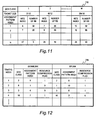
- Fig. 11 is an explanatory diagram of a QoS class management table 735 according to the first embodiment of this invention.
- the QoS class management table 735 is a table that defines QoS classes received by the base station 201a, and is referred to by the connection control unit 732.
- the QoS class management table 735 is set in advance when the system starts to run, and the content thereof is not changed dynamically by other processing units while the system is running.
- Fig. 11 M different QoS classes are defined and numbered from 1 to M in ascending order of packet size.
- a packet size and one of N different assignment patterns are defined for each QoS class.
- the N assignment patterns are numbered from 1 to N in descending order of number of RBs.
- the MCS index is a number assigned to a combination of a modulation scheme and a transport block size (TBS) number.
- TBS transport block size
- the meaning of the MCS index is defined in the table 7.1.7.1-1 of TS 36.213 (v8.4.0), which is standardized by 3GPP (refer to web site of 3GPP http://www.../ftp/Specs/html-info/36213.htm).
- the TBS number corresponds to the coding rate.
- a combination of a TBS number and the number of RBs determines the packet size according to the table 7.1.7.2.1-1 of TS 36.213 (v8.4.0).
- Fig. 12 is an explanatory diagram of a QoS-guaranteed traffic management table 736 according to the first embodiment of this invention.
- the QoS-guaranteed traffic management table 736 is a table that holds information on a call requiring QoS guarantee, and is referred to and updated by the connection control unit 732.
- the QoS-guaranteed traffic management table 736 contains, for each call requiring QoS guarantee that the base station 201a has permitted to access, the identification number of the call (traffic index), a downlink QoS class, a downlink assignment pattern, a downlink resource compression flag, an uplink QoS class, an uplink assignment pattern, and an uplink resource compression flag.
- a resource compression flag is a flag that indicates whether or not resource compression processing described later is to be executed.
- a resource compression flag having a value "0" means that the resource compression processing has not been executed, and a resource compression flag having a value "1" means that the resource compression processing has been executed.
- the QoS-guaranteed traffic management table 736 may be two separate tables, and one of the tables is for uplink traffic indexes and the other is for downlink traffic indexes.
- the controller 730 also includes processing units and tables that are for executing other types of control than those described above (for example, transmission power control and synchronization). However, these processing units and tables are not directly related to this invention, and a detailed description thereof is omitted.
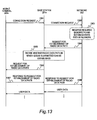
- Fig. 13 is a sequence diagram illustrating communication steps that are taken when QoS guarantee is started according to the first embodiment of this invention.
- a user requests via the terminal 202a to enable the user to start using a service provided over the network 203 (Step 1301 and Step 1302).
- the network 203 ensures network resources necessary for the requested service, and establishes a data path where QoS is guaranteed (Step 1303). Thereafter, the network 203 requests the base station 201a to establish a radio data path where QoS is guaranteed (Step 1304).
- the base station 201a decides whether or not the requested radio data path may be established (Step 1305).
- the base station 201a When establishing the requested radio data path is not possible, the base station 201a replies to the network 203 that the radio data path has not been established successfully.
- the base station 201a When establishing the requested radio data path is possible, the base station 201a establishes the radio data path where QoS is guaranteed between the base station 201a and the terminal 202a (Step 1306 and Step 1307). The base station 201a then replies to the network 203 to notify the network 203 whether the radio data path has successfully been established (Step 1308).
- Steps 1306 and 1307 the network 203 starts communication at the requested level of QoS.
- the network 203 When the attempt to establish the radio data path where QoS is guaranteed fails in Steps 1306 and 1307, the network 203 operates according to a policy of the network 203.
- a common policy that dictates the operation of the network 203 when an attempt to establish a radio data path fails is to refuse access to the base station 201a, or to execute Step 1304 and subsequent steps again at a quality lower than the requested quality. Whichever the policy is, the base station 201a follows an instruction that is sent from the network 203 next.
- Step 1305 to Step 1308 for establishing a radio data path is described referring to a flow chart of Fig. 14 .
- Fig. 14 is a flow chart illustrating the operation of the connection control unit 732 to establish a radio data path according to the first embodiment of this invention.
- the connection control unit 732 refers to the content of a request for establishment of radio data path 1304 received from the network 203 to judge whether or not the QoS of the downlink communication needs to be guaranteed (Step 1401). When it is judged as a result that QoS guarantee is necessary, the connection control unit 732 judges whether or not the downlink communication may be guaranteed of QoS (Step 1402). When the QoS of the downlink communication does not need to be guaranteed, on the other hand, the connection control unit 732 proceeds to Step 1403. Information about the necessity/non-necessity of QoS guarantee is contained in the request for establishment of radio data path 1304.
- connection control unit 732 sends a message to the effect that establishing the radio data path has not been possible to the network 203 in response to the request for establishment of radio data path 1304 (Step 1411). The connection control unit 732 then ends the processing.
- the connection control unit 732 refers to the content of the request for establishment of radio data path 1304 to judge whether or not the QoS of the uplink communication needs to be guaranteed (Step 1403).
- the connection control unit 732 judges whether or not the uplink communication may be guaranteed of QoS (Step 1404).
- the connection control unit 732 proceeds to Step 1405.
- connection control unit 732 sends an instruction that invalidates resource reservation to the scheduler 731 (Step 1410) and proceeds to Step 1411.
- the connection control unit 732 sends a request for establishment of radio data path 1306 to the terminal 202a (Step 1405), and receives a response to the request for establishment of radio data path 1307 from the terminal 202a (Step 1406).
- Step 1406 When the response received from the terminal 202a in Step 1406 says that the radio data path has not been established successfully, the connection control unit 732 proceeds to Step 1410.
- connection control unit 732 When the response received from the terminal 202a in Step 1406 says that the radio data path has successfully been established, the connection control unit 732 registers the QoS class and assignment pattern of the downlink communication as well as the QoS class and assignment pattern of the uplink communication in the QoS-guaranteed traffic management table 736 (Step 1407). The connection control unit 732 also sends to the scheduler 731 an instruction that validates resource reservation for the relevant new call (Step 1408).
- the connection control unit 732 updates the QoS-guaranteed traffic management table 736 in Step 1407 by rewriting the assignment pattern of every existing call that has been a target of the resource compression processing with an assignment pattern that applies after the resource compression, and by setting "1" to the resource compression flag of the existing call.
- the connection control unit 732 sends to the scheduler 731 an instruction that validates resource reservation for every existing call that has been a target of the resource compression processing.
- connection control unit 732 sends a response to the request for establishment of radio data path 1308 to the effect that establishing the radio data path has been finished to the network 203 in response to the request for establishment of radio data path 1304 (Step 1409).
- the connection control unit 732 then ends the processing.
- Step 1402 The processing of judging whether or not QoS may be guaranteed in Step 1402 and Step 1404 is described next referring to an operation flow chart of Fig. 15 .
- Fig. 15 is a flow chart illustrating processing that is executed by the connection control unit to judge whether guaranteeing QoS is possible according to the first embodiment of this invention.
- the connection control unit 732 calculates a packet size necessary for a data transmission rate requested in the request for establishment of radio data path 1304, and refers to the QoS class management table 735 to decide a QoS class that is associated with the necessary packet size (Step 1501).
- the connection control unit 732 next sets the assignment pattern index to "1" (Step 1502), and selects the number of RBs that is associated with the decided QoS class and that has an assignment pattern index "1.”
- the connection control unit 732 makes an inquiry to the scheduler 731 about whether new assignment at the selected number of RBs ( K RBs) is possible (Step 1503). In the case where the scheduler 731 replies to the inquiry that the assignment is possible, the connection control unit 732 determines that QoS may be guaranteed (Step 1507).
- the connection control unit 732 refers to the assignment pattern index (Step 1504).
- the connection control unit 732 increments the assignment pattern index by 1 (Step 1506) and returns to Step 1503.
- the connection control unit 732 therefore compresses radio resources (Step 1505).
- Step 1505 results in the successful ensuring of radio resources in an amount necessary for a new call
- the connection control unit 732 decides that QoS may be guaranteed (Step 1507).
- the connection control unit 732 decides that QoS guarantee is not possible (Step 1508).
- connection control unit 732 guarantees QoS with respect to a new call by changing the MCS and the number of RBs, instead of changing the requested packet size.
- Step 1505 The operation of the resource compression processing in Step 1505 is described next referring to an operation flow chart of Fig. 16 .
- Fig. 16 is a flow chart illustrating the operation of the resource compression processing by the connection control unit 732 according to the first embodiment of this invention.
- the connection control unit 732 selects M for the QoS class number (Step 1601), and refers to the QoS-guaranteed traffic management table 736 to judge whether or not there is an existing call that is associated with this QoS class and that has "0" as the value of its resource compression flag (Step 1602).
- the connection control unit 732 judges that at least one existing call has not undergone resource compression, and selects one of the existing calls that have "0" as the resource compression flag value (Step 1603).
- the connection control unit 732 next judges whether or not the index of an assignment pattern currently applied to the selected existing call (Existing Call A) (assignment pattern index n ) is smaller than N (Step 1604).
- the number of RBs in the assignment pattern having an assignment pattern index n' is K'.
- the connection control unit 732 next sends to the scheduler 731 an inquiry about whether reassignment of K' RBs to Existing Call A is executable (Step 1606). In the case where the scheduler 731 replies that the reassignment is executable as a result, the connection control unit 732 calculates the total number of free RBs remaining after the assignment pattern n' is applied to Existing Call A, and compares the number of free RBs against K, which is the number of RBs necessary for a new call (Step 1607). When it is judged as a result that the total number of free RBs is equal to or larger than K, the connection control unit 732 decides that radio resources have successfully been ensured (Step 1608), and ends the resource compression processing. When it is judged in Step 1607 that the number of free RBs is smaller than K, the connection control unit 732 decides that further resource compression is necessary to ensure enough radio resources, and returns to Step 1602.
- the connection control unit 732 judges whether or not the QoS class number that is currently selected is larger than 1 (Step 1609). When the current QoS class number is larger than 1, the connection control unit 732 decrements the QoS class number by 1 (Step 1610) and returns to Step 1602. When it is judged in Step 1609 that the current QoS class number is 1, which is the lower limit of the QoS class number, the connection control unit 732 decides that radio resources have not been ensured successfully (Step 1611), and ends the resource compression processing.
- connection control unit 732 reduces RBs assigned to existing calls, i.e., releases RBs assigned to ongoing calls, in a situation close to congestion, and assigns the released RBs to a new call.
- Existing calls that are reduced in number of assigned RBs through the above-mentioned processing are selected in descending order of QoS class number. In other words, existing calls that are relatively high in number of RBs are selected first.
- connection control unit 732 redistributes free RBs to be added to the rest of the ongoing calls, thereby increasing the number of RBs of the ongoing calls.
- Fig. 17 is a flow chart illustrating processing that is executed by the connection control unit 732 to add radio resources to an existing call according to the first embodiment of this invention.
- the connection control unit 732 selects 1 as the QoS class number (Step 1701), and refers to the QoS-guaranteed traffic management table 736 to judge whether or not there is an existing call that is associated with this QoS class and that has "1" as the value of its resource compression flag (Step 1702).
- the connection control unit 732 judges that at least one existing call has undergone resource compression, and selects one of the existing calls that have "1" as the resource compression flag value (Step 1703).
- connection control unit 732 next sends to the scheduler 731 a reassignment executability inquiry about whether reassignment of K ' RBs to Existing Call A is executable (Step 1705). In the case where the scheduler 731 replies that the reassignment is inexecutable as a result, the connection control unit 732 returns to Step 1702.
- connection control unit 732 updates the QoS-guaranteed traffic management table 736 by changing the assignment pattern index of Existing Call A to n ' and setting 0 to the resource compression flag of Existing Call A (Step 1706).
- the connection control unit 732 also sends to the scheduler 731 an instruction that validates resource reservation (Step 1707), and returns to Step 1702.
- the connection control unit 732 judges that the currently selected QoS class does not include an existing call that has undergone resource compression, and judges whether or not the currently selected QoS class number is smaller than M (Step 1708). When the currently selected QoS class number is smaller than M , the connection control unit 732 increments the QoS class number by 1 (Step 1709) and returns to Step 1702. When it is judged in Step 1708 that the currently selected QoS class number is M , which is the upper limit of the QoS class number, the processing of adding radio resources is ended.
- connection control unit 732 assigns as large an amount of radio resources as possible to a new call within a range in which the requested level of QoS is sufficiently guaranteed, thus setting the order of modulation and the coding rate low. This makes the error rate at the same SNR lower than when the order of modulation and the coding rate are high. Consequently, the base station 201a may guarantee the new call a good quality of service in terms of delay and data transmission rate for the new call more securely.
- connection control unit 732 reduces radio resources assigned to an existing call by raising the order of modulation and the coding rate, instead of changing the packet size.
- the base station 201a thus assigns necessary radio resources to the new call while maintaining the data transmission rate of the existing call.
- the base station 201a may therefore lower the blocking rate of new calls without disconnecting existing calls or lowering the data transmission rate of existing calls.
- the base station 201a may prevent a processing delay from growing.
- a second embodiment of this invention differs from the first embodiment in the configuration of a QoS-guaranteed traffic management table 736A stored in the base stations 201 a and 201b and the operation of the resource compression processing in Step 1505.
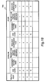
- Fig. 18 is an explanatory diagram of the QoS-guaranteed traffic management table 736A according to the second embodiment of this invention.
- the QoS-guaranteed traffic management table 736A in the second embodiment is obtained by adding to the QoS-guaranteed traffic management table 736 in the first embodiment a "priority for keeping assigned resource" field for a downlink traffic and an uplink traffic of each call in communication.
- the "priority for keeping assigned resource” is an indicator that indicates for each call the degree of insistence to keep the resource amount assigned to the call and not to compress the assigned resources.
- a larger priority value means a higher degree of insistence to keep assigned radio resources and a greater refusal to resource compression.
- Fig. 19 is a flow chart illustrating the operation of resource compression processing that is executed by the connection control unit 732 according to the second embodiment of this invention.
- Fig. 19 steps that are the same as those in the resource compression processing of Step 1505 in the first embodiment are denoted by the same numbers that are used in Fig. 16 , and a detailed description thereof is omitted here.
- connection control unit 732 in the second embodiment executes Steps 1601 to 1603 in the same manner as described in the first embodiment referring to Fig. 16 .
- the connection control unit 732 compares the priority for keeping assigned resource of the selected existing call (Existing Call A) against a predetermined threshold Pt (Step 1901).
- the connection control unit 732 judges that the degree of insistence to keep radio resources assigned to Existing Call A is low, and proceeds to Step 1604 to execute Step 1604 and subsequent steps in the same manner as described in the first embodiment referring to Fig. 16 .
- connection control unit 732 judges that the degree of insistence to keep radio resources assigned to Existing Call A is high, and returns to Step 1602 instead of reducing the resource amount that is assigned to Existing Call A. Returning to Step 1602, the connection control unit 732 repeats the processing.
- a priority is set to each existing call, and hence the base station 201 a may perform resource compression selectively on existing calls that tolerate deterioration in terms of error rate, delay, and the like.
- a third embodiment of this invention differs from the second embodiment in the operation of the resource compression processing of Step 1505 performed in the base stations 201a and 201b.
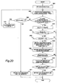
- Fig. 20 is a flow chart illustrating the operation of the resource compression processing that is executed by the connection control unit 732 according to the third embodiment of this invention.
- Fig. 20 steps that are the same as those in the resource compression processing of Step 1505 in the first embodiment are denoted by the same numbers that are used in Fig. 16 , and a detailed description thereof is omitted here.
- connection control unit 732 executes Steps 1601 to 1603 in the same manner as described in the first embodiment referring to Fig. 16 .
- the connection control unit 732 divides the number of RBs that are assigned to the selected existing call (Existing Call A) by the packet size, uses the resultant value as a cost function, and compares the value of the cost function against a predetermined threshold C t (Step 2001).
- the connection control unit 732 judges that the amount of radio resources assigned to Existing Call A is sufficiently large with respect to the packet size, and compares the priority for keeping assigned resource of Existing Call A against the predetermined threshold Pt (Step 2002).
- the connection control unit 732 judges that the degree of insistence to keep radio resources assigned to Existing Call A is low, and selects from the QoS class management table 735 an assignment pattern to be newly applied to the Existing Call A for resource compression (Step 2003).
- the new assignment pattern is selected out of assignment patterns that make the value of the cost function equal to or smaller than Ct, and is one that has the smallest assignment pattern index among those assignment patterns (assignment pattern number n' ).
- the connection control unit 732 then proceeds to Step 1606 to execute Step 1606 and subsequent steps in the same manner as described in the first embodiment referring to Fig. 16 .
- the connection control unit 732 returns to Step 1602 to repeat the processing.
- connection control unit 732 judges that the amount of radio resources assigned to Existing Call A is small with respect to the packet size, and returns to Step 1602 to repeat the processing.
- Step 2002 the connection control unit 732 returns to Step 1602 and repeats the processing.
- the base station 201a compresses radio resources such that the amount of occupied radio resources per data transmission rate is below a given value. Resources may thus be assigned evenly among a plurality of traffic flows.
- the base station 201a guarantees the requested quality of service without fail.
- the base station 201a guarantees QoS in a manner that lowers the blocking rate of new calls, without disconnecting existing calls and without lowering the data transmission rate of existing calls.
Landscapes
- Engineering & Computer Science (AREA)
- Signal Processing (AREA)
- Computer Networks & Wireless Communication (AREA)
- Quality & Reliability (AREA)
- Mobile Radio Communication Systems (AREA)
Claims (10)
- Station de base (201a, 201b) reliée à un réseau filaire (203) et à un réseau sans fil pour établir une communication entre le réseau filaire (203) et le réseau sans fil selon une qualité de service prédéterminée, comportant :une unité de commande de connexion (732),une unité de conservation d'informations de qualité de service (735, 736), etune unité de gestion de ressources radio (731, 733, 734),l'unité de conservation d'informations de qualité de service (735, 736) étant configurée pour :conserver une combinaison de la qualité de service, d'un ensemble de schéma de modulation et de codage, et d'une quantité de ressources radio, etconserver des informations d'association qui associent la combinaison à un appel en cours qui est en communication,l'unité de gestion de ressources radio (731, 733, 734) étant configurée pour :conserver des informations concernant des ressources radio qui sont attribuées à l'appel en cours et des ressources radio qui ne sont pas attribuées à l'appel en cours, etcalculer une quantité des ressources radio non attribuées à partir des informations concernant les ressources radio non attribuées, etl'unité de commande de connexion (732) étant configurée pour :sélectionner, à partir de l'unité de conservation d'informations de qualité de service (735, 736), une ou plusieurs combinaisons de l'ensemble du schéma de modulation et de codage, et de la quantité de ressources radio qui sont associées à la qualité de service établie pour un nouvel appel entrant,déterminer, à partir des quantités de ressources radio d'une ou plusieurs combinaisons sélectionnées, la quantité de ressources radio qui est égale ou inférieure à la quantité des ressources radio non attribuées,attribuer, au nouvel appel entrant, la combinaison qui est associée à la quantité de ressources radio déterminée et à la qualité de service établie pour le nouvel appel entrant,réduire les ressources radio attribuées à l'appel en cours en augmentant l'ordre de modulation et le taux de codage sans changer la qualité de service dans un cas où chaque quantité de ressources radio dans la combinaison ou les combinaisons sélectionnées dépasse la quantité des ressources radio non attribuées qui est conservée dans l'unité de gestion de ressources radio (731, 733, 734), etattribuer, au nouvel appel entrant, une quantité de ressources radio libérées de l'appel en cours et l'ensemble du schéma de modulation et de codage qui est associé à la quantité de ressources radio libérées.
- Station de base (201a, 201b) selon la revendication 1, dans laquelle l'unité de commande de connexion (732) est configurée pour réduire les ressources radio attribuées à un appel en cours qui dispose d'une plus grande quantité de ressources radio attribuées en premier sans changer la qualité de service.
- Station de base (201a, 201b) selon la revendication 1, dans laquelle
l'unité de conservation d'informations de qualité de service (735, 736) est configurée pour conserver une priorité de l'appel en cours, et
l'unité de commande de connexion (732) est configurée pour réduire les ressources radio attribuées à l'appel en cours dont la priorité est inférieure à un seuil spécifié à l'avance. - Station de base (201a, 201b) selon la revendication 1, dans laquelle l'unité de commande de connexion (732) est configurée pour :calculer une taille de paquet de l'appel sur la base de la qualité de service établie pour l'appel,calculer la quantité de ressources radio attribuée par taille de paquet calculée à l'appel en cours, etréduire les ressources radio attribuées à l'appel en cours dont la quantité d'attribution calculée est importante dans un cas où la quantité d'attribution calculée est supérieure à un seuil prédéterminé.
- Station de base (201a, 201b) selon la revendication 1, dans laquelle l'unité de commande de connexion (732) est configurée pour :libérer des ressources radio attribuées à l'appel dont la communication est terminée, etattribuer les ressources radio libérées à l'appel en cours sans changer la qualité de service de l'appel en cours.
- Système de communication sans fil ayant une station de base (201a, 201b) qui est reliée à un réseau filaire (203) et à un réseau sans fil, dans lequel
le système de communication sans fil établit une communication entre le réseau filaire (203) et le réseau sans fil selon une qualité de service prédéterminée,
le système de communication sans fil comporte une unité de commande de connexion (732), une unité de conservation d'informations de qualité de service (735, 736), et une unité de gestion de ressources radio (731, 733, 734),
l'unité de conservation d'informations de qualité de service (735, 736) est configurée pour :conserver une combinaison de la qualité de service, d'un ensemble de schéma de modulation et de codage, et d'une quantité de ressources radio, etconserver des informations d'associations qui associent la combinaison à un appel en cours qui est en communication,l'unité de gestion de ressources radio (731, 733, 734) est configurée pour :conserver des informations concernant des ressources radio qui sont attribuées à l'appel en cours et des ressources radio qui ne sont pas attribuées à l'appel en cours, et
calculer une quantité des ressources radio non attribuées à partir des informations concernant les ressources radio non attribuées, et
l'unité de commande de connexion (732) est configurée pour :sélectionner, à partir de l'unité de conservation d'informations de qualité de service (735, 736), une ou plusieurs combinaisons de l'ensemble du schéma de modulation et de codage, et de la quantité de ressources radio qui sont associées à la qualité de service établie pour un nouvel appel entrant,déterminer, à partir des quantités de ressources radio d'une ou plusieurs combinaisons sélectionnées, la quantité de ressource radio qui est égale ou inférieure à la quantité des ressources radio non attribuées,attribuer, au nouvel appel entrant, la combinaison qui est associée à la quantité de ressources radio déterminée et à la qualité de service établie pour le nouvel appel entrant,réduire les ressources radio attribuées à l'appel en cours en augmentant l'ordre de modulation et le taux de codage sans changer la qualité de service dans un cas où chaque quantité de ressources radio dans la combinaison ou les combinaisons sélectionnées dépasse la quantité des ressources radio non attribuées qui est conservée dans l'unité de gestion de ressources radio (731,7 133,734), etattribuer, au nouvel appel entrant, une quantité de ressources radio libérées de l'appel en cours et l'ensemble du schéma de modulation et de codage qui est associé à la quantité de ressources radio libérées. - Système de communication sans fil selon la revendication 6, dans lequel l'unité de commande de connexion (732) est configurée pour réduire les ressources radio attribuées à un appel en cours qui dispose d'une plus grande quantité de ressources radio attribuées en premier sans changer la qualité de service.
- Système de communication, sans fil selon la revendication 6, dans lequel
l'unité de conservation d'informations de qualité de service (735, 736) est configurée pour conserver une priorité de l'appel en cours, et
l'unité de commande de connexion (732) est configurée pour réduire les ressources radio attribuées à l'appel en cours dont la priorité est inférieure à un seuil spécifié à l'avance. - Système de communication sans fil selon la revendication 6, dans lequel l'unité de commande de connexion (732) est configurée pour :calculer une taille de paquet de l'appel sur la base de la qualité de service établie pour l'appel,calculer la quantité de ressources radio attribuée par taille de paquet calculée à l'appel en cours, etréduire les ressources radio attribuées à l'appel en cours dont la quantité d'attribution calculée est importante dans un cas où la quantité d'attribution calculée est supérieure à un seuil prédéterminé.
- Système de communication sans fil selon la revendication 6, dans lequel l'unité de commande de connexion (732) est configurée pour :libérer des ressources radio attribuées à l'appel dont la communication est terminée, etattribuer les ressources radio libérées à l'appel en cours sans changer la qualité de service de l'appel en cours.
Applications Claiming Priority (1)
| Application Number | Priority Date | Filing Date | Title |
|---|---|---|---|
| JP2008325984A JP5173786B2 (ja) | 2008-12-22 | 2008-12-22 | 無線基地局装置および無線通信システム |
Publications (3)
| Publication Number | Publication Date |
|---|---|
| EP2200387A2 EP2200387A2 (fr) | 2010-06-23 |
| EP2200387A3 EP2200387A3 (fr) | 2011-11-30 |
| EP2200387B1 true EP2200387B1 (fr) | 2013-02-20 |
Family
ID=42028263
Family Applications (1)
| Application Number | Title | Priority Date | Filing Date |
|---|---|---|---|
| EP09015568A Not-in-force EP2200387B1 (fr) | 2008-12-22 | 2009-12-16 | Contrôle d'accès pour communication cellulaire sans fil |
Country Status (4)
| Country | Link |
|---|---|
| US (1) | US8503295B2 (fr) |
| EP (1) | EP2200387B1 (fr) |
| JP (1) | JP5173786B2 (fr) |
| CN (1) | CN101765165B (fr) |
Families Citing this family (9)
| Publication number | Priority date | Publication date | Assignee | Title |
|---|---|---|---|---|
| PL2493134T3 (pl) | 2009-04-02 | 2017-10-31 | Ericsson Telefon Ab L M | Techniki dla obsługi ruchu sieciowego |
| JP5704160B2 (ja) * | 2010-02-23 | 2015-04-22 | 日本電気株式会社 | 無線基地局およびその適応変調制御方法 |
| WO2012013238A1 (fr) * | 2010-07-29 | 2012-02-02 | Telefonaktiebolaget L M Ericsson (Publ) | Manipulation de trafic sur le réseau par l'intermédiaire d'un accès fixe |
| JP5867772B2 (ja) * | 2010-09-10 | 2016-02-24 | ソニー株式会社 | 受信装置、およびプログラム |
| WO2014207930A1 (fr) * | 2013-06-28 | 2014-12-31 | 富士通株式会社 | Dispositif de station de base, dispositif de station mobile, dispositif de commande de qualité de service, et procédé de communication |
| CN105284081A (zh) * | 2013-07-29 | 2016-01-27 | 富士通株式会社 | 传输机制的转换方法、用户设备以及基站 |
| WO2019010697A1 (fr) * | 2017-07-14 | 2019-01-17 | Telefonaktiebolaget Lm Ericsson (Publ) | Procédé et appareil pour adaptation de liaison dans un environnement de trafic partagé |
| CN109600248B (zh) * | 2017-09-30 | 2020-09-08 | 华为技术有限公司 | 服务质量的确定方法、装置及存储介质 |
| US11523377B2 (en) | 2020-02-14 | 2022-12-06 | T-Mobile Usa, Inc. | LTE resource allocation controller |
Family Cites Families (21)
| Publication number | Priority date | Publication date | Assignee | Title |
|---|---|---|---|---|
| JPH05347783A (ja) | 1992-06-15 | 1993-12-27 | Fujitsu Ltd | 移動通信システムにおけるチャネル割当制御装置 |
| JPH0799526A (ja) * | 1993-09-28 | 1995-04-11 | Hitachi Ltd | 通信制御方式 |
| JP3014023B2 (ja) | 1995-01-31 | 2000-02-28 | 日本電気株式会社 | Tdma通信システムにおけるタイムスロット割り当て方法 |
| JP2000068969A (ja) * | 1998-08-20 | 2000-03-03 | Nec Corp | ディジタル通信装置 |
| JP2002044719A (ja) * | 2000-07-19 | 2002-02-08 | Nec Mobiling Ltd | 移動体通信システムおよびその通信スロット制御方法 |
| JP3788908B2 (ja) * | 2000-12-28 | 2006-06-21 | 株式会社エヌ・ティ・ティ・ドコモ | 受付制御装置及びその新規接続受付制御方法 |
| GB0104610D0 (en) * | 2001-02-23 | 2001-04-11 | Koninkl Philips Electronics Nv | Radio communication system |
| JP4213445B2 (ja) * | 2001-10-01 | 2009-01-21 | 株式会社エヌ・ティ・ティ・ドコモ | リソース制御方法、移動通信システム及び基地局 |
| CN1251525C (zh) | 2001-10-01 | 2006-04-12 | 株式会社Ntt都科摩 | 资源控制方法、移动通信系统、基站和移动站 |
| KR100547852B1 (ko) * | 2002-01-09 | 2006-02-01 | 삼성전자주식회사 | 이동통신 시스템에서 호 수락 방법 |
| JP4128881B2 (ja) | 2003-01-22 | 2008-07-30 | 三菱電機株式会社 | 無線チャネル割当方法、基地局装置及び移動体通信端末 |
| JP2005086479A (ja) * | 2003-09-09 | 2005-03-31 | Hitachi Kokusai Electric Inc | 伝送装置 |
| KR20050050322A (ko) * | 2003-11-25 | 2005-05-31 | 삼성전자주식회사 | 직교주파수다중화방식의 이동통신시스템에서 적응변조 방법 |
| US20050159166A1 (en) * | 2004-01-21 | 2005-07-21 | Telefonaktiebolaget Lm Ericsson (Publ) | Quality of service controlled link adaptation |
| FR2875667A1 (fr) * | 2004-09-22 | 2006-03-24 | France Telecom | Procede de preemption pour la gestion des ressources radio dans un reseau de communication mobile |
| US7292825B2 (en) * | 2004-10-19 | 2007-11-06 | Ipwireless, Inc. | Retransmission scheme in a cellular communication system |
| US7724656B2 (en) * | 2005-01-14 | 2010-05-25 | Telefonaktiebolaget Lm Ericsson (Publ) | Uplink congestion detection and control between nodes in a radio access network |
| EP2079246A4 (fr) * | 2006-11-01 | 2012-08-22 | Fujitsu Ltd | Appareil de communication sans fil et procédé de communication sans fil |
| JP4835465B2 (ja) | 2007-02-26 | 2011-12-14 | 株式会社日立製作所 | 無線通信システムおよび端末 |
| US7978724B1 (en) * | 2008-01-29 | 2011-07-12 | Clear Wireless Llc | Systems and methods of allocating radio resources |
| US8036136B1 (en) * | 2008-03-12 | 2011-10-11 | Clear Wireless Llc | System and method of allocating sub-channels |
-
2008
- 2008-12-22 JP JP2008325984A patent/JP5173786B2/ja not_active Expired - Fee Related
-
2009
- 2009-12-16 EP EP09015568A patent/EP2200387B1/fr not_active Not-in-force
- 2009-12-18 US US12/641,366 patent/US8503295B2/en not_active Expired - Fee Related
- 2009-12-21 CN CN2009102587758A patent/CN101765165B/zh not_active Expired - Fee Related
Also Published As
| Publication number | Publication date |
|---|---|
| EP2200387A3 (fr) | 2011-11-30 |
| JP5173786B2 (ja) | 2013-04-03 |
| EP2200387A2 (fr) | 2010-06-23 |
| US20100157831A1 (en) | 2010-06-24 |
| CN101765165A (zh) | 2010-06-30 |
| CN101765165B (zh) | 2013-08-28 |
| US8503295B2 (en) | 2013-08-06 |
| JP2010148021A (ja) | 2010-07-01 |
Similar Documents
| Publication | Publication Date | Title |
|---|---|---|
| EP2200387B1 (fr) | Contrôle d'accès pour communication cellulaire sans fil | |
| EP2484167B1 (fr) | Commande de réglage de ressources pour transmission utilisant des ressources à base de contention | |
| EP2271031B1 (fr) | Indicateur de qualité du canal pour un canal de temps, fréquence et spatial dans un réseau d'accès radio terrestre | |
| EP1932296B1 (fr) | Ordonnancement des systemes de communication sans fil | |
| EP1941765B1 (fr) | Ordonnancement de groupe dans des systèmes de communication sans fil | |
| US8937911B2 (en) | Method and system for sharing resources in a wireless communication network | |
| EP2294747B1 (fr) | Programmation de transmissions de données dans des réseaux de transmission de données à porteuses multiples | |
| US8325655B2 (en) | Multi-carrier HSDPA channel establishing method and the multi-carrier downlink packet data transmitting method | |
| US20080247375A1 (en) | Network-Based Inter-Cell Power Control For Multi-Channel Wireless Networks | |
| EP2391045B1 (fr) | Station de base radio et procédé d'allocation des ressources radio | |
| CN101578903B (zh) | 基站装置以及通信控制方法 | |
| US20070189304A1 (en) | MAC-driven transport block size selection at a physical layer | |
| GB2427097A (en) | Method of communicating uplink signalling information | |
| KR20080109772A (ko) | 무선 통신 시스템에서의 공통 시간 주파수 무선 자원 | |
| CN113286320B (zh) | 一种控制信道单元cce聚合等级调整方法及装置 | |
| WO2010112085A1 (fr) | Commande de charge dynamique pour voies de signalisation descendantes | |
| US8842625B2 (en) | Wireless scheduling considering overhead cost estimate | |
| CN114363920B (zh) | 一种数据传输、配置方法、终端及网络设备 | |
| US8594031B2 (en) | Method and apparatus for providing quality of service for similar priority logical channels | |
| Capozzi et al. | UTRAN LTE downlink system performance under realistic control channel constraints | |
| KR101757173B1 (ko) | 영속적인 스케줄링을 갖는 제어 채널 송신을 위한 방법 | |
| CN107820216B (zh) | 基于sc-mtch的调度方法及装置 | |
| US8320320B2 (en) | Method and system for downlink transmission scheduling in multi-carrier networks |
Legal Events
| Date | Code | Title | Description |
|---|---|---|---|
| PUAI | Public reference made under article 153(3) epc to a published international application that has entered the european phase |
Free format text: ORIGINAL CODE: 0009012 |
|
| 17P | Request for examination filed |
Effective date: 20100331 |
|
| AK | Designated contracting states |
Kind code of ref document: A2 Designated state(s): AT BE BG CH CY CZ DE DK EE ES FI FR GB GR HR HU IE IS IT LI LT LU LV MC MK MT NL NO PL PT RO SE SI SK SM TR |
|
| AX | Request for extension of the european patent |
Extension state: AL BA RS |
|
| PUAL | Search report despatched |
Free format text: ORIGINAL CODE: 0009013 |
|
| AK | Designated contracting states |
Kind code of ref document: A3 Designated state(s): AT BE BG CH CY CZ DE DK EE ES FI FR GB GR HR HU IE IS IT LI LT LU LV MC MK MT NL NO PL PT RO SE SI SK SM TR |
|
| AX | Request for extension of the european patent |
Extension state: AL BA RS |
|
| RIC1 | Information provided on ipc code assigned before grant |
Ipc: H04L 27/00 20060101ALI20111025BHEP Ipc: H04L 5/00 20060101ALI20111025BHEP Ipc: H04L 1/00 20060101ALI20111025BHEP Ipc: H04W 72/08 20090101AFI20111025BHEP Ipc: H04L 27/36 20060101ALI20111025BHEP |
|
| GRAP | Despatch of communication of intention to grant a patent |
Free format text: ORIGINAL CODE: EPIDOSNIGR1 |
|
| RIC1 | Information provided on ipc code assigned before grant |
Ipc: H04L 1/00 20060101ALI20120704BHEP Ipc: H04L 27/36 20060101ALI20120704BHEP Ipc: H04W 72/08 20090101AFI20120704BHEP Ipc: H04L 5/00 20060101ALI20120704BHEP Ipc: H04L 27/00 20060101ALI20120704BHEP |
|
| GRAS | Grant fee paid |
Free format text: ORIGINAL CODE: EPIDOSNIGR3 |
|
| GRAA | (expected) grant |
Free format text: ORIGINAL CODE: 0009210 |
|
| AK | Designated contracting states |
Kind code of ref document: B1 Designated state(s): AT BE BG CH CY CZ DE DK EE ES FI FR GB GR HR HU IE IS IT LI LT LU LV MC MK MT NL NO PL PT RO SE SI SK SM TR |
|
| REG | Reference to a national code |
Ref country code: GB Ref legal event code: FG4D |
|
| REG | Reference to a national code |
Ref country code: SE Ref legal event code: TRGR |
|
| REG | Reference to a national code |
Ref country code: CH Ref legal event code: EP |
|
| REG | Reference to a national code |
Ref country code: AT Ref legal event code: REF Ref document number: 598010 Country of ref document: AT Kind code of ref document: T Effective date: 20130315 Ref country code: CH Ref legal event code: NV Representative=s name: TROESCH SCHEIDEGGER WERNER AG, CH |
|
| REG | Reference to a national code |
Ref country code: IE Ref legal event code: FG4D |
|
| REG | Reference to a national code |
Ref country code: NL Ref legal event code: T3 |
|
| REG | Reference to a national code |
Ref country code: DE Ref legal event code: R096 Ref document number: 602009013382 Country of ref document: DE Effective date: 20130418 |
|
| REG | Reference to a national code |
Ref country code: AT Ref legal event code: MK05 Ref document number: 598010 Country of ref document: AT Kind code of ref document: T Effective date: 20130220 |
|
| REG | Reference to a national code |
Ref country code: LT Ref legal event code: MG4D |
|
| PG25 | Lapsed in a contracting state [announced via postgrant information from national office to epo] |
Ref country code: NO Free format text: LAPSE BECAUSE OF FAILURE TO SUBMIT A TRANSLATION OF THE DESCRIPTION OR TO PAY THE FEE WITHIN THE PRESCRIBED TIME-LIMIT Effective date: 20130520 Ref country code: AT Free format text: LAPSE BECAUSE OF FAILURE TO SUBMIT A TRANSLATION OF THE DESCRIPTION OR TO PAY THE FEE WITHIN THE PRESCRIBED TIME-LIMIT Effective date: 20130220 Ref country code: IS Free format text: LAPSE BECAUSE OF FAILURE TO SUBMIT A TRANSLATION OF THE DESCRIPTION OR TO PAY THE FEE WITHIN THE PRESCRIBED TIME-LIMIT Effective date: 20130620 Ref country code: LT Free format text: LAPSE BECAUSE OF FAILURE TO SUBMIT A TRANSLATION OF THE DESCRIPTION OR TO PAY THE FEE WITHIN THE PRESCRIBED TIME-LIMIT Effective date: 20130220 Ref country code: ES Free format text: LAPSE BECAUSE OF FAILURE TO SUBMIT A TRANSLATION OF THE DESCRIPTION OR TO PAY THE FEE WITHIN THE PRESCRIBED TIME-LIMIT Effective date: 20130531 Ref country code: BG Free format text: LAPSE BECAUSE OF FAILURE TO SUBMIT A TRANSLATION OF THE DESCRIPTION OR TO PAY THE FEE WITHIN THE PRESCRIBED TIME-LIMIT Effective date: 20130520 |
|
| PG25 | Lapsed in a contracting state [announced via postgrant information from national office to epo] |
Ref country code: FI Free format text: LAPSE BECAUSE OF FAILURE TO SUBMIT A TRANSLATION OF THE DESCRIPTION OR TO PAY THE FEE WITHIN THE PRESCRIBED TIME-LIMIT Effective date: 20130220 Ref country code: PL Free format text: LAPSE BECAUSE OF FAILURE TO SUBMIT A TRANSLATION OF THE DESCRIPTION OR TO PAY THE FEE WITHIN THE PRESCRIBED TIME-LIMIT Effective date: 20130220 Ref country code: PT Free format text: LAPSE BECAUSE OF FAILURE TO SUBMIT A TRANSLATION OF THE DESCRIPTION OR TO PAY THE FEE WITHIN THE PRESCRIBED TIME-LIMIT Effective date: 20130620 Ref country code: GR Free format text: LAPSE BECAUSE OF FAILURE TO SUBMIT A TRANSLATION OF THE DESCRIPTION OR TO PAY THE FEE WITHIN THE PRESCRIBED TIME-LIMIT Effective date: 20130521 Ref country code: LV Free format text: LAPSE BECAUSE OF FAILURE TO SUBMIT A TRANSLATION OF THE DESCRIPTION OR TO PAY THE FEE WITHIN THE PRESCRIBED TIME-LIMIT Effective date: 20130220 Ref country code: SI Free format text: LAPSE BECAUSE OF FAILURE TO SUBMIT A TRANSLATION OF THE DESCRIPTION OR TO PAY THE FEE WITHIN THE PRESCRIBED TIME-LIMIT Effective date: 20130220 Ref country code: BE Free format text: LAPSE BECAUSE OF FAILURE TO SUBMIT A TRANSLATION OF THE DESCRIPTION OR TO PAY THE FEE WITHIN THE PRESCRIBED TIME-LIMIT Effective date: 20130220 |
|
| PG25 | Lapsed in a contracting state [announced via postgrant information from national office to epo] |
Ref country code: HR Free format text: LAPSE BECAUSE OF FAILURE TO SUBMIT A TRANSLATION OF THE DESCRIPTION OR TO PAY THE FEE WITHIN THE PRESCRIBED TIME-LIMIT Effective date: 20130220 |
|
| PG25 | Lapsed in a contracting state [announced via postgrant information from national office to epo] |
Ref country code: SK Free format text: LAPSE BECAUSE OF FAILURE TO SUBMIT A TRANSLATION OF THE DESCRIPTION OR TO PAY THE FEE WITHIN THE PRESCRIBED TIME-LIMIT Effective date: 20130220 Ref country code: CZ Free format text: LAPSE BECAUSE OF FAILURE TO SUBMIT A TRANSLATION OF THE DESCRIPTION OR TO PAY THE FEE WITHIN THE PRESCRIBED TIME-LIMIT Effective date: 20130220 Ref country code: EE Free format text: LAPSE BECAUSE OF FAILURE TO SUBMIT A TRANSLATION OF THE DESCRIPTION OR TO PAY THE FEE WITHIN THE PRESCRIBED TIME-LIMIT Effective date: 20130220 Ref country code: RO Free format text: LAPSE BECAUSE OF FAILURE TO SUBMIT A TRANSLATION OF THE DESCRIPTION OR TO PAY THE FEE WITHIN THE PRESCRIBED TIME-LIMIT Effective date: 20130220 Ref country code: DK Free format text: LAPSE BECAUSE OF FAILURE TO SUBMIT A TRANSLATION OF THE DESCRIPTION OR TO PAY THE FEE WITHIN THE PRESCRIBED TIME-LIMIT Effective date: 20130220 |
|
| PLBE | No opposition filed within time limit |
Free format text: ORIGINAL CODE: 0009261 |
|
| STAA | Information on the status of an ep patent application or granted ep patent |
Free format text: STATUS: NO OPPOSITION FILED WITHIN TIME LIMIT |
|
| 26N | No opposition filed |
Effective date: 20131121 |
|
| REG | Reference to a national code |
Ref country code: DE Ref legal event code: R097 Ref document number: 602009013382 Country of ref document: DE Effective date: 20131121 |
|
| REG | Reference to a national code |
Ref country code: NL Ref legal event code: V1 Effective date: 20140701 |
|
| REG | Reference to a national code |
Ref country code: CH Ref legal event code: PL |
|
| PG25 | Lapsed in a contracting state [announced via postgrant information from national office to epo] |
Ref country code: MC Free format text: LAPSE BECAUSE OF FAILURE TO SUBMIT A TRANSLATION OF THE DESCRIPTION OR TO PAY THE FEE WITHIN THE PRESCRIBED TIME-LIMIT Effective date: 20130220 Ref country code: LU Free format text: LAPSE BECAUSE OF FAILURE TO SUBMIT A TRANSLATION OF THE DESCRIPTION OR TO PAY THE FEE WITHIN THE PRESCRIBED TIME-LIMIT Effective date: 20131216 |
|
| REG | Reference to a national code |
Ref country code: IE Ref legal event code: MM4A |
|
| PG25 | Lapsed in a contracting state [announced via postgrant information from national office to epo] |
Ref country code: IE Free format text: LAPSE BECAUSE OF NON-PAYMENT OF DUE FEES Effective date: 20131216 Ref country code: CH Free format text: LAPSE BECAUSE OF NON-PAYMENT OF DUE FEES Effective date: 20131231 Ref country code: LI Free format text: LAPSE BECAUSE OF NON-PAYMENT OF DUE FEES Effective date: 20131231 Ref country code: NL Free format text: LAPSE BECAUSE OF NON-PAYMENT OF DUE FEES Effective date: 20140701 |
|
| PG25 | Lapsed in a contracting state [announced via postgrant information from national office to epo] |
Ref country code: SM Free format text: LAPSE BECAUSE OF FAILURE TO SUBMIT A TRANSLATION OF THE DESCRIPTION OR TO PAY THE FEE WITHIN THE PRESCRIBED TIME-LIMIT Effective date: 20130220 |
|
| PG25 | Lapsed in a contracting state [announced via postgrant information from national office to epo] |
Ref country code: TR Free format text: LAPSE BECAUSE OF FAILURE TO SUBMIT A TRANSLATION OF THE DESCRIPTION OR TO PAY THE FEE WITHIN THE PRESCRIBED TIME-LIMIT Effective date: 20130220 Ref country code: CY Free format text: LAPSE BECAUSE OF FAILURE TO SUBMIT A TRANSLATION OF THE DESCRIPTION OR TO PAY THE FEE WITHIN THE PRESCRIBED TIME-LIMIT Effective date: 20130220 |
|
| PG25 | Lapsed in a contracting state [announced via postgrant information from national office to epo] |
Ref country code: MK Free format text: LAPSE BECAUSE OF FAILURE TO SUBMIT A TRANSLATION OF THE DESCRIPTION OR TO PAY THE FEE WITHIN THE PRESCRIBED TIME-LIMIT Effective date: 20130220 Ref country code: HU Free format text: LAPSE BECAUSE OF FAILURE TO SUBMIT A TRANSLATION OF THE DESCRIPTION OR TO PAY THE FEE WITHIN THE PRESCRIBED TIME-LIMIT; INVALID AB INITIO Effective date: 20091216 |
|
| PG25 | Lapsed in a contracting state [announced via postgrant information from national office to epo] |
Ref country code: IT Free format text: LAPSE BECAUSE OF NON-PAYMENT OF DUE FEES Effective date: 20130220 Ref country code: MT Free format text: LAPSE BECAUSE OF FAILURE TO SUBMIT A TRANSLATION OF THE DESCRIPTION OR TO PAY THE FEE WITHIN THE PRESCRIBED TIME-LIMIT Effective date: 20130220 |
|
| REG | Reference to a national code |
Ref country code: FR Ref legal event code: PLFP Year of fee payment: 7 |
|
| PG25 | Lapsed in a contracting state [announced via postgrant information from national office to epo] |
Ref country code: IT Free format text: LAPSE BECAUSE OF NON-PAYMENT OF DUE FEES Effective date: 20131216 |
|
| REG | Reference to a national code |
Ref country code: FR Ref legal event code: PLFP Year of fee payment: 8 |
|
| PGFP | Annual fee paid to national office [announced via postgrant information from national office to epo] |
Ref country code: DE Payment date: 20161213 Year of fee payment: 8 Ref country code: FR Payment date: 20161111 Year of fee payment: 8 Ref country code: GB Payment date: 20161214 Year of fee payment: 8 |
|
| PGFP | Annual fee paid to national office [announced via postgrant information from national office to epo] |
Ref country code: SE Payment date: 20161213 Year of fee payment: 8 |
|
| REG | Reference to a national code |
Ref country code: DE Ref legal event code: R119 Ref document number: 602009013382 Country of ref document: DE |
|
| GBPC | Gb: european patent ceased through non-payment of renewal fee |
Effective date: 20171216 |
|
| PG25 | Lapsed in a contracting state [announced via postgrant information from national office to epo] |
Ref country code: SE Free format text: LAPSE BECAUSE OF NON-PAYMENT OF DUE FEES Effective date: 20171217 |
|
| REG | Reference to a national code |
Ref country code: FR Ref legal event code: ST Effective date: 20180831 |
|
| PG25 | Lapsed in a contracting state [announced via postgrant information from national office to epo] |
Ref country code: DE Free format text: LAPSE BECAUSE OF NON-PAYMENT OF DUE FEES Effective date: 20180703 Ref country code: FR Free format text: LAPSE BECAUSE OF NON-PAYMENT OF DUE FEES Effective date: 20180102 |
|
| PG25 | Lapsed in a contracting state [announced via postgrant information from national office to epo] |
Ref country code: GB Free format text: LAPSE BECAUSE OF NON-PAYMENT OF DUE FEES Effective date: 20171216 |