EP2200403A1 - Stromregulierte Lichtemissionsvorrichtung zur Verwendung im Fahrzeug - Google Patents
Stromregulierte Lichtemissionsvorrichtung zur Verwendung im Fahrzeug Download PDFInfo
- Publication number
- EP2200403A1 EP2200403A1 EP08167800A EP08167800A EP2200403A1 EP 2200403 A1 EP2200403 A1 EP 2200403A1 EP 08167800 A EP08167800 A EP 08167800A EP 08167800 A EP08167800 A EP 08167800A EP 2200403 A1 EP2200403 A1 EP 2200403A1
- Authority
- EP
- European Patent Office
- Prior art keywords
- light emitting
- switch
- connected electrically
- unit
- current
- Prior art date
- Legal status (The legal status is an assumption and is not a legal conclusion. Google has not performed a legal analysis and makes no representation as to the accuracy of the status listed.)
- Granted
Links
Images

Classifications
-
- H—ELECTRICITY
- H05—ELECTRIC TECHNIQUES NOT OTHERWISE PROVIDED FOR
- H05B—ELECTRIC HEATING; ELECTRIC LIGHT SOURCES NOT OTHERWISE PROVIDED FOR; CIRCUIT ARRANGEMENTS FOR ELECTRIC LIGHT SOURCES, IN GENERAL
- H05B47/00—Circuit arrangements for operating light sources in general, i.e. where the type of light source is not relevant
- H05B47/20—Responsive to malfunctions or to light source life; for protection
- H05B47/28—Circuit arrangements for protecting against abnormal temperature
-
- H—ELECTRICITY
- H05—ELECTRIC TECHNIQUES NOT OTHERWISE PROVIDED FOR
- H05B—ELECTRIC HEATING; ELECTRIC LIGHT SOURCES NOT OTHERWISE PROVIDED FOR; CIRCUIT ARRANGEMENTS FOR ELECTRIC LIGHT SOURCES, IN GENERAL
- H05B45/00—Circuit arrangements for operating light-emitting diodes [LED]
- H05B45/50—Circuit arrangements for operating light-emitting diodes [LED] responsive to malfunctions or undesirable behaviour of LEDs; responsive to LED life; Protective circuits
- H05B45/52—Circuit arrangements for operating light-emitting diodes [LED] responsive to malfunctions or undesirable behaviour of LEDs; responsive to LED life; Protective circuits in a parallel array of LEDs
Definitions
- the invention relates to a light emitting device, more particularly to a current-regulated light emitting device for vehicle use.
- the voltage regulating unit 65 When the electric power source 61 is unstable such that the drive voltage therefrom fluctuates, the voltage regulating unit 65 will operate to adjust the drive voltage to an appropriate value and to supply a stable current for the light emitting unit 64. In view of the need for continuous operation of the voltage regulating unit 65, the operating temperature thereof will increase, and prolonged operation at high temperatures affects operating stability and service life of the voltage regulating unit 65.
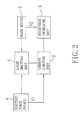
- a current-regulated light emitting device for vehicle use of the present invention comprises a light emitting unit and a current limiting unit.
- the light emitting device includes at least one light emitting module that has a light emitting component.
- the current limiting unit includes a first switch, a first bias unit, a second switch and a second bias unit.
- the first switch is adapted for making and breaking an electrical circuit between the light emitting unit and the electric power source.
- the first bias unit is connected electrically to the first switch, is adapted to be connected electrically to the electric power source, and causes the first switch to conduct such that the first switch makes the electrical circuit between the light emitting unit and the electric power source when the electric power source provides the drive voltage to the first bias unit, thereby resulting in current flow from the electric power source through the light emitting unit and the first switch to activate the light emitting unit.
- the second switch is connected electrically to the first switch.
- the second bias unit is connected electrically to the first and second switches, and causes the second switch to conduct when amount of current flowing through the first switch exceeds a predetermined threshold. Conduction of the second switch forces the first switch to turn off so as to break the electrical circuit between the light emitting unit and the electric power source, thereby interrupting the current flow through the light emitting unit.
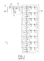
- the light emitting unit 1 is used as a vehicle light for illumination, is adapted for electrical connection to the electric power source 4 and the brake device 5, and includes a plurality of light emitting modules 11 connected in parallel, and three protective components 12.
- Each light emitting module 11 includes a first light emitting component (D1), a second light emitting component (D2), and a pair of current limiting resistors (R). It is noted that, in practice, the number of the light emitting components of each light emitting module 11 is not limited to two.
- the current limiting resistors (R) of each light emitting module 11 are connected in parallel, and the parallel-connected current limiting resistors (R) are connected in series between the respective first light emitting component (D1) and the protective components 12.
- the first switch (Q1) is a n-channel depletion-type metal-oxide-semiconductor field-effect transistor (MOSFET). In practice, other components that can serve the same function may be used.
- the first switch (Q1) has a first control end (G), a first input end (D), and a first output end (S).
- the first control end (G) is the gate and is connected electrically to the first bias unit.
- the first input end (D) is the drain and is connected electrically to the cathodes of the second light emitting components (D2) of the light emitting modules 11 of the light emitting unit 1.
- the first output end (S) is the source and is connected electrically to the first resistors (R10) of the second bias unit.
- the first switch (Q1) must be capable of bearing a voltage, which has a value larger than the drive voltage (V1), between the first input end (D) and the first output end (S).
- the fourth resistor (R4) is connected electrically at one end to the brake device 5 via one of the protective components 12, and is further connected electrically at the other end to the fifth resistor (R5) and the second capacitor (C2).
- the fifth resistor (R5) is connected in parallel to the second capacitor (C2), and the fifth resistor (R5) and the second capacitor (C2) are grounded at one end.
- the coupling resistors (R6) are connected in parallel, and the parallel-connected coupling resistors (R6) are connected electrically at one end to the first output end (S) and the second control end (B), and are further connected electrically at another end to the third switch (Q3).
- the third switch (Q3) is a n-channel depletion-type MOSFET, and has a third control end (G) connected electrically to a junction of the fourth and fifth resistors (R4, R5), a third input end (D) connected electrically to the coupling resistors (R6), and a third output end (S) connected electrically to the second output end (E), which is grounded.
- the third control end (G) is the gate, the third input end (D) is the drain, and the third output end (S) is the source of the MOSFET.
Landscapes
- Lighting Device Outwards From Vehicle And Optical Signal (AREA)
- Circuit Arrangement For Electric Light Sources In General (AREA)
Priority Applications (2)
| Application Number | Priority Date | Filing Date | Title |
|---|---|---|---|
| DE602008002336T DE602008002336D1 (de) | 2008-10-29 | 2008-10-29 | Stromregulierte Lichtemissionsvorrichtung zur Verwendung im Fahrzeug |
| EP08167800A EP2200403B1 (de) | 2008-10-29 | 2008-10-29 | Stromregulierte Lichtemissionsvorrichtung zur Verwendung im Fahrzeug |
Applications Claiming Priority (1)
| Application Number | Priority Date | Filing Date | Title |
|---|---|---|---|
| EP08167800A EP2200403B1 (de) | 2008-10-29 | 2008-10-29 | Stromregulierte Lichtemissionsvorrichtung zur Verwendung im Fahrzeug |
Publications (2)
| Publication Number | Publication Date |
|---|---|
| EP2200403A1 true EP2200403A1 (de) | 2010-06-23 |
| EP2200403B1 EP2200403B1 (de) | 2010-08-25 |
Family
ID=40513893
Family Applications (1)
| Application Number | Title | Priority Date | Filing Date |
|---|---|---|---|
| EP08167800A Active EP2200403B1 (de) | 2008-10-29 | 2008-10-29 | Stromregulierte Lichtemissionsvorrichtung zur Verwendung im Fahrzeug |
Country Status (2)
| Country | Link |
|---|---|
| EP (1) | EP2200403B1 (de) |
| DE (1) | DE602008002336D1 (de) |
Cited By (1)
| Publication number | Priority date | Publication date | Assignee | Title |
|---|---|---|---|---|
| EP2440018A1 (de) * | 2010-09-29 | 2012-04-11 | Rohm Co., Ltd. | LED-Ansteuerungsvorrichtung für Automobile |
Citations (5)
| Publication number | Priority date | Publication date | Assignee | Title |
|---|---|---|---|---|
| US5765940A (en) * | 1995-10-31 | 1998-06-16 | Dialight Corporation | LED-illuminated stop/tail lamp assembly |
| US6414437B1 (en) | 1999-09-23 | 2002-07-02 | Reitter & Schefenacker Gmbh & Co. Kg | Apparatus and method for controlling illumination devices of vehicles |
| WO2004068909A1 (en) * | 2003-01-27 | 2004-08-12 | Matsushita Electric Industrial Co., Ltd. | Multichip led lighting device |
| US20070182337A1 (en) * | 2006-02-03 | 2007-08-09 | Honeywell International Inc. | Increasing Reliability of Operation of Light Emitting Diode Arrays at Higher Operating Temperatures and its Use in the Lamps of Automobiles |
| EP1860922A1 (de) | 2006-05-24 | 2007-11-28 | Power Integrations, Inc. | Verfahren und Vorrichtung zur Stromversorgung lichtemittierender Dioden-Arrays |
-
2008
- 2008-10-29 EP EP08167800A patent/EP2200403B1/de active Active
- 2008-10-29 DE DE602008002336T patent/DE602008002336D1/de active Active
Patent Citations (5)
| Publication number | Priority date | Publication date | Assignee | Title |
|---|---|---|---|---|
| US5765940A (en) * | 1995-10-31 | 1998-06-16 | Dialight Corporation | LED-illuminated stop/tail lamp assembly |
| US6414437B1 (en) | 1999-09-23 | 2002-07-02 | Reitter & Schefenacker Gmbh & Co. Kg | Apparatus and method for controlling illumination devices of vehicles |
| WO2004068909A1 (en) * | 2003-01-27 | 2004-08-12 | Matsushita Electric Industrial Co., Ltd. | Multichip led lighting device |
| US20070182337A1 (en) * | 2006-02-03 | 2007-08-09 | Honeywell International Inc. | Increasing Reliability of Operation of Light Emitting Diode Arrays at Higher Operating Temperatures and its Use in the Lamps of Automobiles |
| EP1860922A1 (de) | 2006-05-24 | 2007-11-28 | Power Integrations, Inc. | Verfahren und Vorrichtung zur Stromversorgung lichtemittierender Dioden-Arrays |
Cited By (6)
| Publication number | Priority date | Publication date | Assignee | Title |
|---|---|---|---|---|
| EP2440018A1 (de) * | 2010-09-29 | 2012-04-11 | Rohm Co., Ltd. | LED-Ansteuerungsvorrichtung für Automobile |
| US8754592B2 (en) | 2010-09-29 | 2014-06-17 | Rohm Co., Ltd. | Automobile LED driving device |
| US9148915B2 (en) | 2010-09-29 | 2015-09-29 | Rohm Co., Ltd. | Automobile LED driving device |
| EP3626536A1 (de) * | 2010-09-29 | 2020-03-25 | Rohm Co., Ltd. | Led-ansteuerungsvorrichtung für automobile |
| EP3741622A1 (de) * | 2010-09-29 | 2020-11-25 | Rohm Co., Ltd. | Led-ansteuerungsvorrichtung für automobile |
| EP4046870A1 (de) * | 2010-09-29 | 2022-08-24 | Rohm Co., Ltd. | Led-ansteuerungsvorrichtung für automobile |
Also Published As
| Publication number | Publication date |
|---|---|
| EP2200403B1 (de) | 2010-08-25 |
| DE602008002336D1 (de) | 2010-10-07 |
Similar Documents
| Publication | Publication Date | Title |
|---|---|---|
| US8198834B2 (en) | LED drive circuit | |
| US7994725B2 (en) | Floating switch controlling LED array segment | |
| EP2269421B1 (de) | Eingabekanalerkennungsvorrichtung mit geringem verlust für ein direktstromgetriebenes beleuchtungssystem | |
| CN102132479A (zh) | 电源装置和照明装置 | |
| US7952290B2 (en) | Current-regulated light emitting device for vehicle use | |
| CN104703337B (zh) | 车辆用灯具 | |
| US8421374B2 (en) | Apparatus for driving load | |
| US8729821B2 (en) | Semiconductor light source lighting circuit and control method | |
| EP2474988A1 (de) | Lichtemittierende Diodenantriebssteuerungsschaltung | |
| CN108235506B (zh) | 用于车灯组件的恒定电流功率驱动器电路 | |
| US7728532B2 (en) | Circuit device for light-emitting diode driving and stabilizing system | |
| JP4944553B2 (ja) | 照明装置 | |
| JP2014151717A (ja) | 車両用灯具用の過電圧保護装置 | |
| AU2008217015B2 (en) | Current-regulated light emitting device for vehicle use | |
| EP2200403B1 (de) | Stromregulierte Lichtemissionsvorrichtung zur Verwendung im Fahrzeug | |
| US9282619B2 (en) | Light device for a ceiling fan, switch device of the same, and method for preventing abnormal operation of the light device using the switch device | |
| JP4955502B2 (ja) | 光源点灯用回路およびそれを備えた発光装置 | |
| CN113573944A (zh) | 车辆用灯具及点亮电路 | |
| CN104067696B (zh) | Led点亮装置 | |
| KR101512727B1 (ko) | 발광다이오드 구동 회로 | |
| CN105960058B (zh) | 发光二极管调光开关保护电路 | |
| KR20160066887A (ko) | 잔광현상 방지기능이 구비된 led조명 전원공급회로 | |
| US20200092969A1 (en) | Vehicle lighting device | |
| JP4677859B2 (ja) | Led照明装置 | |
| JP4805985B2 (ja) | 車両用定電流発光装置 |
Legal Events
| Date | Code | Title | Description |
|---|---|---|---|
| GRAP | Despatch of communication of intention to grant a patent |
Free format text: ORIGINAL CODE: EPIDOSNIGR1 |
|
| GRAS | Grant fee paid |
Free format text: ORIGINAL CODE: EPIDOSNIGR3 |
|
| PUAI | Public reference made under article 153(3) epc to a published international application that has entered the european phase |
Free format text: ORIGINAL CODE: 0009012 |
|
| 17P | Request for examination filed |
Effective date: 20081029 |
|
| AK | Designated contracting states |
Kind code of ref document: A1 Designated state(s): AT BE BG CH CY CZ DE DK EE ES FI FR GB GR HR HU IE IS IT LI LT LU LV MC MT NL NO PL PT RO SE SI SK TR |
|
| GRAA | (expected) grant |
Free format text: ORIGINAL CODE: 0009210 |
|
| AK | Designated contracting states |
Kind code of ref document: B1 Designated state(s): DE ES FR GB |
|
| REG | Reference to a national code |
Ref country code: GB Ref legal event code: FG4D |
|
| REF | Corresponds to: |
Ref document number: 602008002336 Country of ref document: DE Date of ref document: 20101007 Kind code of ref document: P |
|
| AKX | Designation fees paid |
Designated state(s): DE ES FR GB |
|
| PG25 | Lapsed in a contracting state [announced via postgrant information from national office to epo] |
Ref country code: ES Free format text: LAPSE BECAUSE OF FAILURE TO SUBMIT A TRANSLATION OF THE DESCRIPTION OR TO PAY THE FEE WITHIN THE PRESCRIBED TIME-LIMIT Effective date: 20101206 |
|
| PGFP | Annual fee paid to national office [announced via postgrant information from national office to epo] |
Ref country code: ES Payment date: 20101025 Year of fee payment: 3 |
|
| PLBE | No opposition filed within time limit |
Free format text: ORIGINAL CODE: 0009261 |
|
| STAA | Information on the status of an ep patent application or granted ep patent |
Free format text: STATUS: NO OPPOSITION FILED WITHIN TIME LIMIT |
|
| 26N | No opposition filed |
Effective date: 20110526 |
|
| REG | Reference to a national code |
Ref country code: DE Ref legal event code: R097 Ref document number: 602008002336 Country of ref document: DE Effective date: 20110526 |
|
| REG | Reference to a national code |
Ref country code: FR Ref legal event code: PLFP Year of fee payment: 8 |
|
| REG | Reference to a national code |
Ref country code: FR Ref legal event code: PLFP Year of fee payment: 9 |
|
| REG | Reference to a national code |
Ref country code: FR Ref legal event code: PLFP Year of fee payment: 10 |
|
| REG | Reference to a national code |
Ref country code: FR Ref legal event code: PLFP Year of fee payment: 11 |
|
| REG | Reference to a national code |
Ref country code: DE Ref legal event code: R079 Ref document number: 602008002336 Country of ref document: DE Free format text: PREVIOUS MAIN CLASS: H05B0033080000 Ipc: H05B0045000000 |
|
| P01 | Opt-out of the competence of the unified patent court (upc) registered |
Effective date: 20230616 |
|
| PGFP | Annual fee paid to national office [announced via postgrant information from national office to epo] |
Ref country code: GB Payment date: 20250923 Year of fee payment: 18 |
|
| PGFP | Annual fee paid to national office [announced via postgrant information from national office to epo] |
Ref country code: FR Payment date: 20250923 Year of fee payment: 18 |
|
| PGFP | Annual fee paid to national office [announced via postgrant information from national office to epo] |
Ref country code: DE Payment date: 20250918 Year of fee payment: 18 |