EP2200542B1 - Universalausschläger für totalendoprothesen des hüftgelenkes, langschaftkomponenten modularer prothesensysteme oder marknägel - Google Patents
Universalausschläger für totalendoprothesen des hüftgelenkes, langschaftkomponenten modularer prothesensysteme oder marknägel Download PDFInfo
- Publication number
- EP2200542B1 EP2200542B1 EP08841863.7A EP08841863A EP2200542B1 EP 2200542 B1 EP2200542 B1 EP 2200542B1 EP 08841863 A EP08841863 A EP 08841863A EP 2200542 B1 EP2200542 B1 EP 2200542B1
- Authority
- EP
- European Patent Office
- Prior art keywords
- loop
- screw
- bolt
- guide bolt
- universal extractor
- Prior art date
- Legal status (The legal status is an assumption and is not a legal conclusion. Google has not performed a legal analysis and makes no representation as to the accuracy of the status listed.)
- Not-in-force
Links
- 210000004394 hip joint Anatomy 0.000 title 1
- 239000007769 metal material Substances 0.000 claims description 2
- 210000000988 bone and bone Anatomy 0.000 description 8
- 239000007943 implant Substances 0.000 description 8
- 210000002414 leg Anatomy 0.000 description 8
- 238000004873 anchoring Methods 0.000 description 6
- 208000010201 Exanthema Diseases 0.000 description 5
- 201000005884 exanthem Diseases 0.000 description 5
- 210000001624 hip Anatomy 0.000 description 5
- 206010037844 rash Diseases 0.000 description 5
- 239000002184 metal Substances 0.000 description 3
- 238000001356 surgical procedure Methods 0.000 description 3
- 239000002639 bone cement Substances 0.000 description 2
- 238000006073 displacement reaction Methods 0.000 description 2
- 238000011540 hip replacement Methods 0.000 description 2
- 238000002513 implantation Methods 0.000 description 2
- 208000015181 infectious disease Diseases 0.000 description 2
- 230000010354 integration Effects 0.000 description 2
- 238000000034 method Methods 0.000 description 2
- 210000000689 upper leg Anatomy 0.000 description 2
- 244000089486 Phragmites australis subsp australis Species 0.000 description 1
- 210000000588 acetabulum Anatomy 0.000 description 1
- 230000002411 adverse Effects 0.000 description 1
- 238000011882 arthroplasty Methods 0.000 description 1
- 230000008859 change Effects 0.000 description 1
- 239000002131 composite material Substances 0.000 description 1
- 230000007547 defect Effects 0.000 description 1
- 230000002349 favourable effect Effects 0.000 description 1
- 239000012634 fragment Substances 0.000 description 1
- 238000003780 insertion Methods 0.000 description 1
- 230000037431 insertion Effects 0.000 description 1
- 230000008407 joint function Effects 0.000 description 1
- 239000000463 material Substances 0.000 description 1
- 230000007246 mechanism Effects 0.000 description 1
- 210000002445 nipple Anatomy 0.000 description 1
- 230000008569 process Effects 0.000 description 1
- 210000002307 prostate Anatomy 0.000 description 1
- 230000003716 rejuvenation Effects 0.000 description 1
- 210000000323 shoulder joint Anatomy 0.000 description 1
- 239000007787 solid Substances 0.000 description 1
- 125000006850 spacer group Chemical group 0.000 description 1
- 230000007480 spreading Effects 0.000 description 1
- 230000006641 stabilisation Effects 0.000 description 1
- 238000011105 stabilization Methods 0.000 description 1
- 239000003351 stiffener Substances 0.000 description 1
- 239000000725 suspension Substances 0.000 description 1
Images



Classifications
-
- A—HUMAN NECESSITIES
- A61—MEDICAL OR VETERINARY SCIENCE; HYGIENE
- A61F—FILTERS IMPLANTABLE INTO BLOOD VESSELS; PROSTHESES; DEVICES PROVIDING PATENCY TO, OR PREVENTING COLLAPSING OF, TUBULAR STRUCTURES OF THE BODY, e.g. STENTS; ORTHOPAEDIC, NURSING OR CONTRACEPTIVE DEVICES; FOMENTATION; TREATMENT OR PROTECTION OF EYES OR EARS; BANDAGES, DRESSINGS OR ABSORBENT PADS; FIRST-AID KITS
- A61F2/00—Filters implantable into blood vessels; Prostheses, i.e. artificial substitutes or replacements for parts of the body; Appliances for connecting them with the body; Devices providing patency to, or preventing collapsing of, tubular structures of the body, e.g. stents
- A61F2/02—Prostheses implantable into the body
- A61F2/30—Joints
- A61F2/46—Special tools for implanting artificial joints
- A61F2/4603—Special tools for implanting artificial joints for insertion or extraction of endoprosthetic joints or of accessories thereof
- A61F2/4607—Special tools for implanting artificial joints for insertion or extraction of endoprosthetic joints or of accessories thereof of hip femoral endoprostheses
-
- A—HUMAN NECESSITIES
- A61—MEDICAL OR VETERINARY SCIENCE; HYGIENE
- A61F—FILTERS IMPLANTABLE INTO BLOOD VESSELS; PROSTHESES; DEVICES PROVIDING PATENCY TO, OR PREVENTING COLLAPSING OF, TUBULAR STRUCTURES OF THE BODY, e.g. STENTS; ORTHOPAEDIC, NURSING OR CONTRACEPTIVE DEVICES; FOMENTATION; TREATMENT OR PROTECTION OF EYES OR EARS; BANDAGES, DRESSINGS OR ABSORBENT PADS; FIRST-AID KITS
- A61F2/00—Filters implantable into blood vessels; Prostheses, i.e. artificial substitutes or replacements for parts of the body; Appliances for connecting them with the body; Devices providing patency to, or preventing collapsing of, tubular structures of the body, e.g. stents
- A61F2/02—Prostheses implantable into the body
- A61F2/30—Joints
- A61F2/46—Special tools for implanting artificial joints
- A61F2/4603—Special tools for implanting artificial joints for insertion or extraction of endoprosthetic joints or of accessories thereof
- A61F2002/4619—Special tools for implanting artificial joints for insertion or extraction of endoprosthetic joints or of accessories thereof for extraction
-
- A—HUMAN NECESSITIES
- A61—MEDICAL OR VETERINARY SCIENCE; HYGIENE
- A61F—FILTERS IMPLANTABLE INTO BLOOD VESSELS; PROSTHESES; DEVICES PROVIDING PATENCY TO, OR PREVENTING COLLAPSING OF, TUBULAR STRUCTURES OF THE BODY, e.g. STENTS; ORTHOPAEDIC, NURSING OR CONTRACEPTIVE DEVICES; FOMENTATION; TREATMENT OR PROTECTION OF EYES OR EARS; BANDAGES, DRESSINGS OR ABSORBENT PADS; FIRST-AID KITS
- A61F2/00—Filters implantable into blood vessels; Prostheses, i.e. artificial substitutes or replacements for parts of the body; Appliances for connecting them with the body; Devices providing patency to, or preventing collapsing of, tubular structures of the body, e.g. stents
- A61F2/02—Prostheses implantable into the body
- A61F2/30—Joints
- A61F2/46—Special tools for implanting artificial joints
- A61F2/4603—Special tools for implanting artificial joints for insertion or extraction of endoprosthetic joints or of accessories thereof
- A61F2002/4625—Special tools for implanting artificial joints for insertion or extraction of endoprosthetic joints or of accessories thereof with relative movement between parts of the instrument during use
- A61F2002/4627—Special tools for implanting artificial joints for insertion or extraction of endoprosthetic joints or of accessories thereof with relative movement between parts of the instrument during use with linear motion along or rotating motion about the instrument axis or the implantation direction, e.g. telescopic, along a guiding rod, screwing inside the instrument
Definitions
- the invention relates to a universal razor for hip endoprostheses, long shaft components of modular prosthesis systems or intramedullary nails according to the preamble of the claims.
- TEP Total hip arthroplasty
- the font DE 100 14 401 A1 discloses a device for releasing cone-type connectors.
- the latter can be found in modular hip prostheses between the shaft and the neck segment or joint ball and prosthesis neck.
- This instrument has 2 legs, which are supported in each case on the prosthesis parts to be detached and drive them apart by a spreading movement.
- a hip replacement prosthesis which serves to retain hip replacements.
- This Auseller is formed from a tee, consisting of a plate and a leg, wherein the distal end of the Ausellers is mechanically fixed to a loop which protrudes at the opposite end of the plate of the Ausellers.
- the leg of the Ausellers has a threaded rod with screw and turning handle to convert a rotational movement in an axial movement of the loop.
- US 2001/0051830 A1 is a surgical tool for gripping a prosthesis during a surgical procedure (fixation of acetabulum at implantations) known, said tool having a leg as an axial tube, a bolt, a guide pin and a non-openable / non-detachable loop.
- the disadvantage of this technical solution is that the tool can not be used in explantations and the two ends of the loop guided through the holes of the pressure plate are firmly connected to each other, so that the loop can not be exchanged as a wearing part or if different loops are not required different lengths when using the Ausellers are available.
- the tool can only be used with implants that have anchoring possibilities for the loops, since otherwise it is not possible to attach the tool to an implant.
- loops cord, cable
- Achtertouren serves the shoulder joint against lateral dodging or constriction of bone parts by means of the cord or cable.
- the invention is therefore based on the object to provide a prosthesis impactor for hip prostheses, long shaft components modular prosthetic systems or intramedullary nails, which avoids the disadvantages of the prior art, in particular adjustable in length and mechanically stable connections of the Prosthesis shaft through the Auseller, a change of worn loops and a slight explantation of the prostheses while sparing the bony bearing allows.
- the guide pin is mounted axially in the tube of the T-piece and can perform an axial movement.
- a radially arranged screw and the slot in the tube By a radially arranged screw and the slot in the tube, the degree of freedom of rotation of the guide pin is released.
- the helical gear causes an axial force acting on the guide pin pulling force, so that it is pulled into the tube of the T-piece.
- the guide pin is connectable to a wire loop which protrudes at the lower part of the prosthesis deflector.
- the stable orthograde anchoring of the Ausellers takes place on the prosthesis stem by a loop, particularly advantageously consisting of braided material, such as. Metal, which is placed in the operating state in the form of an eight-way around the neck segment.
- a loop particularly advantageously consisting of braided material, such as. Metal, which is placed in the operating state in the form of an eight-way around the neck segment.
- the rope of the loop is tensioned, wherein the lower part of the Ausellers is pressed against the neck segment of the prosthesis stem. Due to the shape of the contact surface of the Auseaurs its gradual self-centering takes place.
- the "pre-loosened" prosthesis stem can be pulled out of the bony medullary canal.
- the rash force can optimally unfold in the razor according to the invention.
- the loop has two free ends, which are provided with holding elements, and that the distal leg has two recesses for insertion of the holding elements, which spatially corresponding recesses in the guide pins are assigned, which can be suspended by the recesses and the holding elements frictionally are halterbar.
- the in Fig. 1 . 2 and 3 Universalaustrainr shown consists of a tee 1, which is formed by the rash plate 11 and a tube as the axial leg 12, a guide pin 2 with screw 21 and a bolt 3 with crank or star grip. 4
- the guide pin 2 is mounted axially in the tube 12 of the T-piece 1 and can perform an axial movement.
- a radially disposed screw 21 which slides in a slot 5 of the tube 12, the degree of freedom of rotation of the guide pin 2 is released.
- the lower part of the bolt 3 is coupled by a helical gear with the guide pin 2.
- the screw gear causes in the operated state an axial force acting on the guide pin 2 tensile force, so that it is pulled into the tube 12 of the T-piece 1.
- the guide pin 2 is connected at its distal end with a loop 6, advantageously a wire loop, which protrudes at the distal part of the universal deflector.
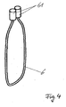
- the loop 6 has, as in Fig. 4 shown, two free ends, which are provided with holding elements 61 and the leg 12 has, as in Fig. 3 and Fig. 5 shown, a long hole 5 for guiding the screw 21 and recesses 7, which spatially corresponding recesses 8 are assigned in the guide pin 2, wherein the retaining elements 61 are suspended by the recesses 7 and 8 and frictionally halterbar by the recesses 8.
- the loop 6 is interchangeable by their suspension by means of the holding elements 61 and the recesses 7 and 8, so that different sized loops can be suspended.
- the stable orthograde anchoring of Universalausditers invention takes place at a proper use of the neck segment of the prosthesis stem through the loop 6, which is particularly advantageously made of braided metallic material which is placed according to the invention in the form of an eight-way around the prosthesis.
- the Universalausditer is supported on the neck segment of the prosthesis stem. Due to the shape of the contact surface of the Ausellers its self-centering.
- the "pre-loosened” prosthesis stem through Strikes a metal hammer against the rash plate 11 of the tee 1 are pulled out of the bony bearing.
- the Universalausbridger invention allows by its adjustable in length and mechanically stable termination explantation of a wide range of worldwide offered hip endoprostheses.
- the loop is easily and quickly replaced by an intact new loop as a wearing part (eg. Tearing by force during use).
Landscapes
- Health & Medical Sciences (AREA)
- Transplantation (AREA)
- Orthopedic Medicine & Surgery (AREA)
- Heart & Thoracic Surgery (AREA)
- Life Sciences & Earth Sciences (AREA)
- Oral & Maxillofacial Surgery (AREA)
- Engineering & Computer Science (AREA)
- Biomedical Technology (AREA)
- Physical Education & Sports Medicine (AREA)
- Vascular Medicine (AREA)
- Cardiology (AREA)
- Animal Behavior & Ethology (AREA)
- General Health & Medical Sciences (AREA)
- Public Health (AREA)
- Veterinary Medicine (AREA)
- Prostheses (AREA)
- Surgical Instruments (AREA)
Description
- Die Erfindung betrifft einen Universalausschläger für Hüftendoprothesen, Langschaftkomponenten modularer Prothesensysteme oder Marknägel gemäß der Gattung der Patentansprüche.
- Verschiedenste Bauformen von chirurgischen Spannvorrichtungen und Ausschlägern sind seit Jahren bekannt. Insbesondere ist die Wirkungsweise der Ausschläger oft unbefriedigend.
- Die Totalendoprothesenplastik (TEP) des Hüftgelenkes ist die am häufigsten durchgeführte Gelenkersatzoperation. Dabei wird das verschlissene natürliche Gelenk durch ein technisches Gelenk ersetzt, welches jedoch sofort einem Verschleiß unterliegt. Auch Infektionen des Implantates sind zwar selten, aber nicht ausgeschlossen.
- Die Folge ist eine steigende Zahl von Wechseloperationen, die als ersten Scluitt eine das knöcherne Implantatlager schonende Entfernung der Prothesenteile notwendig macht, bevor eine Reimplantation einer neuen Prothese möglich wird. Bei septischen Wechseloperationen erfolgt in der Regel ein zweiseitiges Vorgehen mit temporärer Implantation eines Spacers aus Knochenzement.
- Bis vor 20 Jahren war der Markt von zementierten Implantaten beherrscht, d.h. die Schaft- und Pfannenkomponenten wurden mit Knochenzement im natürlichen - Knochen verankert. Die knochenschonende Entfernung derartiger Prothesen war einfach, da die Schaftkomponenten meist einen Kragen besaßen, der einen günstigen Angriffspunkt zum Ausschlagen darstellte.
- In der Folgezeit haben kragenlose, zementfreie und modulare Prothesensysteme bis zum heutigen Tag einen hohen Marktanteil erobert. Die Entfernung dieser ist jedoch ungleich problematischer; insbesondere wenn die knöcherne Integration bei langen zementfreien Prothesenschäften großflächige bis weit in die distalen Markraumabschnitte erfolgt ist. Weiterhin erschwerend für den handelnden Operateur erweist sich die breite Palette unterschiedlicher Prothesentypen zahlreicher Hersteller.
- Nur wenige Prothesenproduzenten haben sich der Demontage bzw. Entfernung der Schaftkomponenten gestellt. Bei der überwiegenden Mehrheit kommen gemäß dem Stand der Technik Universalausschläger zur Anwendung, die als Verankerungspunkt den Schaftkonus, der das einzige genormte Teil des Schaftes darstellt, nutzen. Die Beanspruchung eines Konus auf Zug ist jedoch mechanisch äußerst unzweckmäßig. Oft weisen die Halssegmente der Prothesen unterhalb des Konus eine ungenügende Verjüngung auf, die eine stabile Verankerung des Ausschlägers oft unmöglich macht. Moderne Prothesen sind zudem meist kragenlos, so dass ein tangential zur Schaftachse wirkendes Ausschlaginstrument keinen Angriffspunkt findet. Derartige Hilfsmittel sind wegen ihrer auf das knöcherne Lager wirkenden Scherkräfte problematisch. Ungewollte Schaftfrakturen oder zusätzliche Knochendefekte können die Folge sein. Ebenso unzweckmäßig sind die bisher häufig gebräuchlichen Sledge-Hammer-Vorrichtungen am Ausschläger, die meist nur eine ungenügende Kraftentfaltung ermöglichen und z.T. durch ihre überdimensionierten Ausmaße dem Operateur die Arbeit erschweren.
- Bleiben alle Bemühungen des Operateurs bei der Explantation eines fest knöchern integrierten Prothesenschaftes erfolglos, so bleibt ihm als Ultima ratio nur die langstreckige Osteotomie des knöchernen Prothesenlagers. Damit geht wertvoller knöcherner Markraum für die Reimplantation eines Prothesenschaftes verloren.
- Deutlich problematischer wird dieser Umstand, wenn die Explantation einer festen zementfreien modularen Langschaftprothese oder eines fest verankerten Marknagels nach Osteosynthese bei fehlendem Originalinstrumentarium erfolgen muss. In diesen Fällen sind bereits die Reserven von intakten, knöchernen Markraum für eine Reimplantation nahezu ausgeschöpft. Um ein risikoreiches Großimplantat mit schlechter Gelenkfunktion und erhöhtem Infektionsrisiko zu vermeiden, muss der Operateur besonders sorgsam mit den "Markraumresten" bei der "Vorlockerung" des langen Implantates vorgehen. Als Angriffspunkt für ein Explantationsinstrument steht dann meist nur ein im "Langimplantat" bestehendes Gewinde unbekannter Größe zur Verfügung. Nach dem Stand der Technik ist ein effektives Entfernungsinstrument nur bei sehr wenigen Prothesen oder Marknägeltypen verfügbar.
- Die Schrift
DE 100 14 401 A1 offenbart eine Vorrichtung zum Lösen von Konus-Steckverbindungen. Letztere sind bei modularen Hüftprothesen zwischen Schaft und Halssegment oder Gelenkkugel und Prothesenhals anzutreffen. Dieses Instrument weist 2 Schenkel auf, die sich jeweils an den zu lösenden Prothesenteilen abstützen und diese durch eine Spreizbewegung auseinander treiben. - Ein Instrument zum Spannen und Fixieren von Drahtschlingen, sogenannten Cerclagen, um einen Röhrenknochen beschreibt die Schrift
DE 296 12 072 U1 . Beim Spannvorgang wird dabei das Spannmittel Draht durch einen bewegbaren Schieber axial gezogen und durch ein fixierendes Element gehalten. Die fest am Röhrenknochen haftende Cerclage wird dann verplombt und dient zur Fixierung von Knochenfragmenten bei Frakturen oder Knochentransplantaten. - Aus
FR 2 749 501 A1 - Der Nachteil dieser technischen Lösung besteht darin, dass das distale Ende des Ausschlägers mit der Schlaufe mechanisch fest verbunden ist, so dass die Schlaufe als Verschleißteil nicht auswechselbar ist bzw. dass je nach Bedarf nicht verschiedenste Schlaufen unterschiedlicher Längen beim Einsatz des Ausschlägers nutzbar sind.
- Aus
US 2001/0051830 A1 ist ein chirurgisches Werkzeug zum Greifen einer Prothese während eines chirurgischen Eingriffs (Fixation von Hüftpfannen bei Implantationen) bekannt, wobei dieses Werkzeug einen Schenkel als axiales Rohr, einen Schraubbolzen, einen Führungsbolzen und eine nicht öffenbare / nicht lösbare Schlaufe aufweist. Dabei erfolgt die Befestigung der Drahtschlaufe über eine mobile Druckplatte vermittels mehrerer Ausnehmungen, durch welche die Drahtschlaufe gehaltert wird. - Der Nachteil dieser technischen Lösung besteht darin, dass Werkzeug nicht bei Explantationen einsetzbar ist und die beiden Enden der durch die Löcher der Druckplatte geführten Schlaufe fest miteinander verbunden sind, so dass die Schlaufe als Verschleißteil nicht auswechselbar ist bzw. dass je nach Bedarf nicht verschiedenste Schlaufen unterschiedlicher Längen beim Einsatz des Ausschlägers nutzbar sind.
- Hinzu kommt, dass das Werkzeug nur bei Implantaten einsetzbar ist, welche Verankerungsmöglichkeiten für die Schlaufen aufweisen, da ansonsten kein Anschlingen des Werkzeugs an einem Implantat möglich ist.
- Weiterhin ist die Verwendung von Schlaufen (Kordel, Kabel) in Form von Achtertouren in der Chirurgie aus
DE 38 10 465 A1 undUS 2004/0243131 A1 bekannt, wobei die Achtertouren das Schultergelenk gegen seitliches Auseinanderweichen oder zum Zusammenschnüren von Knochenteilen vermittels der Kordel bzw. Kabel dient. - Der Erfindung liegt daher die Aufgabe zu Grunde, einen Prothesenausschläger für Hüftprothesen, Langschaftkomponenten modularer Prothesensysteme oder Marknägel anzugeben, der die Nachteile des Standes der Technik vermeidet, insbesondere in ihrer Länge einstellbare und mechanisch stabile Anschlingungen des Prothesenschaftes durch den Ausschläger, einen Wechsel der verschlissenen Schlaufen und eine leichte Explantation der Prothesen bei Schonung des knöchernen Lagers ermöglicht.
- Voraussetzung für eine erfolgreiche Entfernung ist eine entsprechende "Vorlockerung" des Prothesenschaftes im knöchernen Lager. Das sollte bei zementfreien, knöchern integrierten Schäften mit großer Vorsicht erfolgen. Als Hilfsmittel würden Spezialmeißel und Kirschnerdrähte zur Anwendung kommen. Ziel ist eine Verringerung der knöchernen Integrationsfläche, um die Ausschlagkraft zur Lösung des Implant-Knochen-Verbundes zu minimieren, bei schlechter mechanischer Knochenqualität Sekundärschäden oder nachteilige Osteotomien des Markraumes zu vermeiden.
- Dazu müssen u.a. folgende Aufgaben bzgl. des Universalausschlägers gelöst werden:
- eine stabile, orthograde Verankerung an Prothesenschäften unterschiedlichster Designs,
- eine optimale Entfaltung der Zugkraft,
- eine Wiederverwendbarkeit sowie
- eine universelle Anwendung bei Schulter- und Ellenbogenendoprothesen und in einer zweiten speziellen Designform auch bei Langschaftkomponenten modularer Systeme sowie diversen Marknägeln.
- Gemäß der Erfindung wird diese Aufgabe durch die kennzeichnenden Merkmale des ersten Patentanspruches gelöst und durch vorteilhafte Ausgestaltungen gemäß den Unteransprüchen ergänzt.
- Das Wesen der Erfindung besteht darin, dass der Universalausschläger aus folgenden Teilen aufgebaut ist:
- T-Stück, wobei der axiale Schenkel aus einem Rohr besteht
- Führungsbolzen mit Ausnehmungen zur Aufnahme der freien Enden einer Schlaufe
- Schraubbolzen mit Kurbel oder Sterngriff
- Der Führungsbolzen ist im Rohr des T-Stückes axial gelagert und kann eine axiale Bewegung ausführen. Durch eine radial angeordnete Schraube sowie das Langloch im Rohr wird der Freiheitsgrad der Rotation des Führungsbolzens aufgehoben.
- Die axiale Verschiebung des Führungsbolzens erfolgt über den axial angeordneten Schraubbolzen. Dieser stützt sich auf der Platte des T-Stückes ab. Der untere Teil des Schraubbolzens ist durch ein Gewinde mit dem Führungsbolzen gekoppeit.
- Das Schraubengetriebe bewirkt eine axial auf den Führungsbolzen wirkende Zugkraft, so dass dieser in das Rohr des T-Stückes gezogen wird. Der Führungsbolzen ist mit einer Drahtschlaufe verbindbar, die am unteren Teil des Prothesenausschlägers herausragt.
- Die stabile orthograde Verankerung des Ausschlägers erfolgt am Prothesenschaft durch eine Schlaufe, besonders vorteilhaft bestehend aus geflochtenem Material, wie bspw. Metall, welche im Betriebszustand in Form einer Achtertour um dessen Halssegment gelegt wird. Durch den oben beschriebenen Mechanismus wird das Seil der Schlaufe gespannt, wobei der untere Teil des Ausschlägers gegen das Halssegment des Prothesenschaftes gepresst wird. Durch die Form der Kontaktfläche des Ausschlägers erfolgt dessen schrittweise Selbstzentrierung. Nun kann durch Schläge eines Metallhammers gegen die Ausschlagplatte des T-Stückes der "vorgelockerte" Prothesenschaft aus dem knöchernen Markraum gezogen werden. Im Gegensatz zu den bisher üblichen Sledge-Hämmein kann sich die Ausschlagkraft bei dem erfindungsgemäßen Ausschläger optimal entfalten.
- Erfindungswesentlich dabei ist, dass die Schlaufe zwei freie Enden besitzt, die mit Halteelementen versehen sind, und dass der distale Schenkel zwei Ausnehmungen zum Einführen der Halteelemente aufweist, denen räumlich korrespondierend Ausnehmungen in dem Führungsbolzen zugeordnet sind, wobei durch die Ausnehmungen die Halteelemente einhängbar und kraftschlüssig halterbar sind.
- Durch die einhängbaren Halteelemente, die sich an den freien Enden der Drahtschlaufe befinden ist, diese beliebig austauschbar.
- Die Wiederverwendbarkeit des Universalausschlägers ist durch die Reversibilität der Verankerung, die Resterilisierbarkeit und die Ersetzbarkeit des Verschleißteils Schlaufe gesichert, so dass Mehrfachanwendungen des erfindungsgemäßen Ausschlägers problemlos möglich sind.
- Die universelle Anwendung des Ausschlägers bei Prothesenschäften unterschiedlichen Designs wird durch die Verankerung mittels Halteelemente-tragender Drahtschlaufe gewährleistet. Eine Anwendung des erfindungsgemäßen Ausschlägers bei Schulter- und Ellenbogenendoprothesen ist ebenfalls möglich möglich.
- Die Erfindung wird nachstehend an Hand der schematischen Zeichnungen näher erläutert. Es zeigt:
- Fig. 1:
- eine Ausführungsform des erfindungsgemäßen Universalausschlägers in schematischer 3-D-Darstellung,
- Fig. 2:
- die Ausführungsform gemäß
Fig. 1 in einer Darstellung der auseinander gefügten Einzelteile, - Fig. 3:
- die Ausführungsform gemäß
Fig. 1 vor dem Einführen der Schlaufe in schematischer 3-D-Darstellung, - Fig. 4:
- eine Darstellung der Schlaufe und
- Fig. 5:
- die Ausführungsform gemäß
Fig. 1 in teilweiser Schnittdarstellung im Bereich der eingeführten Schlaufe, - Der in
Fig. 1 ,2 und 3 dargestellte Universalausschläger besteht aus einem T-Stück 1, welches von der Ausschlagplatte 11 und einem Rohr als axialen Schenkel 12 gebildet wird, einem Führungsbolzen 2 mit Schraube 21 sowie einem Schraubbolzen 3 mit Kurbel oder Sterngriff 4. - Der Führungsbolzen 2 ist im Rohr 12 des T-Stückes 1 axial gelagert und kann eine axiale Bewegung ausführen. Durch eine radial angeordnete Schraube 21, die in einem Langloch 5 des Rohres 12 gleitet, wird der Freiheitsgrad der Rotation des Führungsbolzens 2 aufgehoben.
- Die axiale Verschiebung des Führungsbolzens 2 erfolgt über den axial angeordneten Schraubbolzen 3, welcher sich an der Ausschlagplatte 11 des T-Stückes 1 abstützt. Der untere Teil des Schraubbolzens 3 ist durch ein Schraubengetriebe mit dem Führungsbolzen 2 gekoppelt. Das Schraubengetriebe bewirkt in betriebenem Zustand eine axial auf den Führungsbolzen 2 wirkende Zugkraft, so dass dieser in das Rohr 12 des T-Stückes 1 gezogen wird. Der Führungsbolzen 2 ist an seinem distalen Ende mit einer Schlaufe 6, vorteilhaft einer Drahtschlaufe, verbunden, die am distalen Teil des Universalausschlägers herausragt.
- Die Schlaufe 6 besitzt, wie in
Fig. 4 dargestellt, zwei freie Enden, die mit Halteelementen 61 versehen sind und der Schenkel 12 weist, wie inFig. 3 undFig. 5 dargestellt, ein Langlöch 5 zur Führung der Schraube 21 sowie Ausnehmungen 7 auf, denen räumlich korrespondierend Ausnehmungen 8 in dem Führungsbolzen 2 zugeordnet sind, wobei durch die Ausnehmungen 7 und 8 die Halteelemente 61 einhängbar und durch die Ausnehmungen 8 kraftschlüssig halterbar sind. - Die Schlaufe 6 ist durch ihre Einhängbarkeit vermittels der Halteelemente 61 und der Ausnehmungen 7 und 8 austauschbar, so dass verschieden große Schlaufen einhängbar sind.
- Die stabile orthograde Verankerung des erfindungsgemäßen Universalausschlägers erfolgt bei einer bestimmungsgemäßen Verwendung am Halssegment des Prothesenschaftes durch die Schlaufe 6, die besonders vorteilhaft aus geflochtenem, metallischen Material besteht, welche erfindungsgemäß in Form einer Achtertour um die Prothese gelegt wird. Durch Spannung der Schlaufe 6 stützt sich der Universalausschläger am Halssegment des Prothesenschaftes ab. Durch die Form der Kontaktfläche des Ausschlägers erfolgt dessen Selbstzentrierung. Nun kann der "vorgelockerte" Prothesenschaft durch Schläge eines Metallhammers gegen die Ausschlagplatte 11 des T-Stückes 1 aus dem knöchernen Lager gezogen werden.
- Der erfindungsgemäße Universalausschläger gestattet durch seine in ihrer Länge einstellbare und mechanisch stabile Anschlingung eine Explantation eines breiten Spektrums von weltweit angebotenen Hüftendoprothesen.
- Darüber hinaus ist die Schlaufe als Verschleißteil (bspw. Zerreißen durch Krafteinwirkung bei der Verwendung) einfach und schnell durch eine intakte neue Schlaufe ersetzbar.
- Alle in der Beschreibung, den nachfolgenden Ansprüchen und in den Zeichnungen dargestellten Merkmale können sowohl einzeln, als auch in beliebiger Kombination miteinander erfindungswesentlich sein.
-
- 1
- - T-Stück
- 11
- - Platte
- 12
- - Schenkel
- 2
- - Führungsbolzen
- 21
- - Schraube
- 3
- - Schraubbolzen
- 4
- - Kurbel oder Sterrigriff
- 5
- - Langloch
- 6
- - Schlaufe
- 61
- - Halteelemente
- 7
- - Ausnelunungen im Schenkel
- 8
- - Ausnehmungen im Führungsbolzen
- 9
- - Plastik-Ring
Claims (6)
- Universalausschläger für Hüftendoprothesen umfassend• ein T-Stück (1) bestehend aus einer Platte (11) und einem Schenkel (12), wobei der Schenkel (12) aus einem axialen Rohr gebildet ist,• einen Führungsbolzen (2) mit Schraube (21),• einen Schraubbolzen (3) mit einer Kurbel oder einem Sterngriff (4),wobei der Schraubbolzen (3) drehbar in den Führungsbolzen (12) greift, der Führungsbolzen (2) im Schenkel (12) des T-Stückes (1) axial gelagert und dadurch axial bewegbar ist, und der Führungsbolzen (2) an seinem distalen Ende mit einer Schlaufe (6) verbunden ist, die an dem der Platte (11) gegenüberliegenden Ende des Universalausschlägers aus dem Rohr herausragt, dadurch gekennzeichnet, dass die Schlaufe (6) zwei freie Enden besitzt, die mit Halteelementen (61) versehen sind,
der Schenkel (12) ein Langloch (5) zur Führung der Schraube (21) sowie Ausnehmungen (7) aufweist, denen räumlich korrespondierend Ausnehmungen (8) in dem Führungsbolzen (2) zugeordnet sind, wobei durch die Ausnehmungen (7 und 8) die Halteelemente (61) einhängbar und durch die Ausnehmungen (8) kraftschlüssig halterbar sind,
die Schraube (21) radial und gleitend in dem Langloch (5) angeordnet ist, so dass der Freiheitsgrad der Rotation des Führungsbolzens (2) im axialen Schenkel (12) aufhebbar ist und sich der Schraubbolzen (3) auf der Platte (11) des T-Stücks (1) abstützt. - Universalausschläger gemäß Anspruch 1, dadurch gekennzeichnet, dass die axiale Verschiebung des Führungsbolzens (2) vermittels des axial angeordneten Schraubbolzens (3) erzeugbar ist.
- Universalausschläger gemäß Anspruch 2, dadurch gekennzeichnet, dass der untere Teil des Schraubbolzens (3) durch ein Gewinde mit dem Führungsbolzen (2) verbunden ist, und wobei das Schraubengetriebe im betriebenen Zustand eine axial auf den Führungsbolzen (2) wirkende Zugkraft bewirkt, so dass dieser in das Rohr des T-Stücks (1) gezogen und dabei die Schlaufe (6) in ihrem eingehängten Zustand bewegt wird.
- Universalausschläger gemäß Anspruch 1, dadurch gekennzeichnet, dass die Schlaufe (6) aus geflochtenem metallischen Material besteht.
- Universalausschläger gemäß Anspruch 4, dadurch gekennzeichnet, dass die Schlaufe (6) eine Drahtschlaufe ist.
- Universalausschläger gemäß einem oder mehrerer der voran stehenden Ansprüche, dadurch gekennzeichnet, dass die Schlaufe (6) in Form einer Achtertour um eine Prothese legbar ist.
Applications Claiming Priority (2)
| Application Number | Priority Date | Filing Date | Title |
|---|---|---|---|
| DE200710051293 DE102007051293B4 (de) | 2007-10-23 | 2007-10-23 | Universalausschläger für Hüftendoprothesen |
| PCT/DE2008/001611 WO2009052776A1 (de) | 2007-10-23 | 2008-09-30 | Universalausschläger für totalendoprothesen des hüftgelenkes, langschaftkomponenten modularer prothesensysteme oder marknägel |
Publications (2)
| Publication Number | Publication Date |
|---|---|
| EP2200542A1 EP2200542A1 (de) | 2010-06-30 |
| EP2200542B1 true EP2200542B1 (de) | 2014-04-30 |
Family
ID=40344416
Family Applications (1)
| Application Number | Title | Priority Date | Filing Date |
|---|---|---|---|
| EP08841863.7A Not-in-force EP2200542B1 (de) | 2007-10-23 | 2008-09-30 | Universalausschläger für totalendoprothesen des hüftgelenkes, langschaftkomponenten modularer prothesensysteme oder marknägel |
Country Status (3)
| Country | Link |
|---|---|
| EP (1) | EP2200542B1 (de) |
| DE (1) | DE102007051293B4 (de) |
| WO (1) | WO2009052776A1 (de) |
Cited By (1)
| Publication number | Priority date | Publication date | Assignee | Title |
|---|---|---|---|---|
| US11918475B2 (en) | 2021-03-31 | 2024-03-05 | DePuy Synthes Products, Inc. | Modular acetabular surgical implant assembly |
Families Citing this family (4)
| Publication number | Priority date | Publication date | Assignee | Title |
|---|---|---|---|---|
| US8470049B2 (en) | 2009-09-01 | 2013-06-25 | Concept, Design And Development, Llc | Neck sparing total hip implant system |
| US8398719B2 (en) | 2009-09-01 | 2013-03-19 | Concept, Design And Development, Llc | Neck sparing total hip implant methods |
| KR102146697B1 (ko) * | 2018-11-23 | 2020-08-21 | 한림대학교 산학협력단 | 침소침습성 강선 제거장치 |
| EP4370043A1 (de) * | 2021-08-11 | 2024-05-22 | Gursharan Singh Chana | Vorrichtung zur verwendung in der chirurgie |
Family Cites Families (7)
| Publication number | Priority date | Publication date | Assignee | Title |
|---|---|---|---|---|
| DE3810465A1 (de) * | 1987-03-31 | 1988-11-17 | Michael M Dr Med Schikorski | Knebelschlinge mit zuggurtungskordel und schliessmechanismus zur operativen behandlung der schultereckgelenkssprengung |
| EP0743049B1 (de) * | 1995-05-18 | 2001-08-29 | Sulzer Orthopädie AG | Künstliche Gelenkschale |
| FR2749501B1 (fr) * | 1996-06-05 | 1998-08-07 | Sferic | Dispositif d'extraction de tiges medullaires |
| DE29612072U1 (de) * | 1996-07-11 | 1996-09-12 | Aesculap Ag, 78532 Tuttlingen | Chirurgische Spannvorrichtung |
| GB2323036B (en) * | 1997-03-14 | 2001-04-11 | Finsbury | Prosthetic implant and surgical tool |
| DE10014401C2 (de) * | 1999-11-25 | 2001-10-04 | Steinicke Maschinen Und Werkze | Abziehinstrument zum Lösen einzelner Teile einer Endoprothese |
| US20040243131A1 (en) * | 2003-02-07 | 2004-12-02 | Dirks Christiaan H.P. | Bone fixing device |
-
2007
- 2007-10-23 DE DE200710051293 patent/DE102007051293B4/de not_active Expired - Fee Related
-
2008
- 2008-09-30 WO PCT/DE2008/001611 patent/WO2009052776A1/de not_active Ceased
- 2008-09-30 EP EP08841863.7A patent/EP2200542B1/de not_active Not-in-force
Cited By (1)
| Publication number | Priority date | Publication date | Assignee | Title |
|---|---|---|---|---|
| US11918475B2 (en) | 2021-03-31 | 2024-03-05 | DePuy Synthes Products, Inc. | Modular acetabular surgical implant assembly |
Also Published As
| Publication number | Publication date |
|---|---|
| DE102007051293A1 (de) | 2009-04-30 |
| DE102007051293B4 (de) | 2014-02-20 |
| EP2200542A1 (de) | 2010-06-30 |
| WO2009052776A1 (de) | 2009-04-30 |
Similar Documents
| Publication | Publication Date | Title |
|---|---|---|
| EP2833842B1 (de) | Wirbelsäulen-implantat, werkzeuge zum einbringen von implantaten zwischen zwei wirbelkörper einer wirbelsäule und operationsset | |
| DE19619093B4 (de) | Marknagelsystem zur Frakturheilung bzw. Knochenverlängerung | |
| EP2756825B1 (de) | Ausschlagwerkzeug für minimalinvasive Prothesenrevision | |
| DE102010048052B4 (de) | Nagel-Schrauben-System für eine Osteosynthese | |
| EP2468216B1 (de) | Implantierbare Prothese zum Ersatz des menschlichen Hüft- oder Kniegelenks und der angrenzenden Knochenabschnitte | |
| EP2200542B1 (de) | Universalausschläger für totalendoprothesen des hüftgelenkes, langschaftkomponenten modularer prothesensysteme oder marknägel | |
| EP1148826B1 (de) | Hohlraspel zur präparation eines röhrenknochens | |
| EP3730097B1 (de) | Probe halsstück für eine gelenkendoprothese | |
| EP1304984B1 (de) | Chirurgisches element | |
| WO2009124719A1 (de) | Modulare femurkopfprothese | |
| EP1994892B1 (de) | Instrumentensatz zur minimal invasiven Vorbereitung einer Knochennagelung | |
| WO2007124607A1 (de) | Schaft für gelenkprothese | |
| EP2806830B1 (de) | Adapter-system für eine endoprothese | |
| EP1139938B1 (de) | Chirurgisches Gerätesatz zum mechanischen entfernen von Knochenzement | |
| EP2898860B1 (de) | Hüftgelenk-Endoprothesen-System | |
| DE202007014948U1 (de) | Universalausschläger für Totalendoprothesen des Hüftgelenkes, Langschaftkomponenten modularer Prothesensysteme oder Marknägel | |
| EP2662055A1 (de) | Verstärkungsimplantat für einen langgestreckten Knochen, insbesondere Femur | |
| EP3135253B1 (de) | Implantierbare prothese zum ersatz des menschlichen kniegelenks | |
| DE19731879A1 (de) | Intrameduläres Schienungssystem für Röhrenknochen | |
| DE10031271B4 (de) | Hüftpfannenimplantationsgerät | |
| DE202007003452U1 (de) | Osteoaktiver Füllstift zum Verschließen intraoperativer Bohr- und Schraubenlöcher | |
| AT502137A1 (de) | Hüftgelenksrevisionseinrichtung | |
| DE202012104671U1 (de) | Schlagapparat mit Schlagstange und Schlaggewicht | |
| EP2345389B1 (de) | Einbringinstrument zum Einschlagen eines Verblockungselementes | |
| CH707804B1 (de) | Zweiteiliger Schaft für eine Hüftgelenksprothese. |
Legal Events
| Date | Code | Title | Description |
|---|---|---|---|
| PUAI | Public reference made under article 153(3) epc to a published international application that has entered the european phase |
Free format text: ORIGINAL CODE: 0009012 |
|
| 17P | Request for examination filed |
Effective date: 20100324 |
|
| AK | Designated contracting states |
Kind code of ref document: A1 Designated state(s): AT BE BG CH CY CZ DE DK EE ES FI FR GB GR HR HU IE IS IT LI LT LU LV MC MT NL NO PL PT RO SE SI SK TR |
|
| AX | Request for extension of the european patent |
Extension state: AL BA MK RS |
|
| DAX | Request for extension of the european patent (deleted) | ||
| GRAP | Despatch of communication of intention to grant a patent |
Free format text: ORIGINAL CODE: EPIDOSNIGR1 |
|
| INTG | Intention to grant announced |
Effective date: 20131128 |
|
| GRAS | Grant fee paid |
Free format text: ORIGINAL CODE: EPIDOSNIGR3 |
|
| GRAA | (expected) grant |
Free format text: ORIGINAL CODE: 0009210 |
|
| AK | Designated contracting states |
Kind code of ref document: B1 Designated state(s): AT BE BG CH CY CZ DE DK EE ES FI FR GB GR HR HU IE IS IT LI LT LU LV MC MT NL NO PL PT RO SE SI SK TR |
|
| REG | Reference to a national code |
Ref country code: GB Ref legal event code: FG4D Free format text: NOT ENGLISH Ref country code: CH Ref legal event code: EP |
|
| REG | Reference to a national code |
Ref country code: AT Ref legal event code: REF Ref document number: 664589 Country of ref document: AT Kind code of ref document: T Effective date: 20140515 |
|
| REG | Reference to a national code |
Ref country code: IE Ref legal event code: FG4D Free format text: LANGUAGE OF EP DOCUMENT: GERMAN |
|
| REG | Reference to a national code |
Ref country code: DE Ref legal event code: R096 Ref document number: 502008011689 Country of ref document: DE Effective date: 20140612 |
|
| REG | Reference to a national code |
Ref country code: LT Ref legal event code: MG4D |
|
| REG | Reference to a national code |
Ref country code: NL Ref legal event code: VDEP Effective date: 20140430 |
|
| PG25 | Lapsed in a contracting state [announced via postgrant information from national office to epo] |
Ref country code: IS Free format text: LAPSE BECAUSE OF FAILURE TO SUBMIT A TRANSLATION OF THE DESCRIPTION OR TO PAY THE FEE WITHIN THE PRESCRIBED TIME-LIMIT Effective date: 20140830 Ref country code: FI Free format text: LAPSE BECAUSE OF FAILURE TO SUBMIT A TRANSLATION OF THE DESCRIPTION OR TO PAY THE FEE WITHIN THE PRESCRIBED TIME-LIMIT Effective date: 20140430 Ref country code: NL Free format text: LAPSE BECAUSE OF FAILURE TO SUBMIT A TRANSLATION OF THE DESCRIPTION OR TO PAY THE FEE WITHIN THE PRESCRIBED TIME-LIMIT Effective date: 20140430 Ref country code: NO Free format text: LAPSE BECAUSE OF FAILURE TO SUBMIT A TRANSLATION OF THE DESCRIPTION OR TO PAY THE FEE WITHIN THE PRESCRIBED TIME-LIMIT Effective date: 20140730 Ref country code: LT Free format text: LAPSE BECAUSE OF FAILURE TO SUBMIT A TRANSLATION OF THE DESCRIPTION OR TO PAY THE FEE WITHIN THE PRESCRIBED TIME-LIMIT Effective date: 20140430 Ref country code: GR Free format text: LAPSE BECAUSE OF FAILURE TO SUBMIT A TRANSLATION OF THE DESCRIPTION OR TO PAY THE FEE WITHIN THE PRESCRIBED TIME-LIMIT Effective date: 20140731 Ref country code: BG Free format text: LAPSE BECAUSE OF FAILURE TO SUBMIT A TRANSLATION OF THE DESCRIPTION OR TO PAY THE FEE WITHIN THE PRESCRIBED TIME-LIMIT Effective date: 20140730 Ref country code: CY Free format text: LAPSE BECAUSE OF FAILURE TO SUBMIT A TRANSLATION OF THE DESCRIPTION OR TO PAY THE FEE WITHIN THE PRESCRIBED TIME-LIMIT Effective date: 20140430 |
|
| PGFP | Annual fee paid to national office [announced via postgrant information from national office to epo] |
Ref country code: DE Payment date: 20140926 Year of fee payment: 7 |
|
| PG25 | Lapsed in a contracting state [announced via postgrant information from national office to epo] |
Ref country code: PL Free format text: LAPSE BECAUSE OF FAILURE TO SUBMIT A TRANSLATION OF THE DESCRIPTION OR TO PAY THE FEE WITHIN THE PRESCRIBED TIME-LIMIT Effective date: 20140430 Ref country code: HR Free format text: LAPSE BECAUSE OF FAILURE TO SUBMIT A TRANSLATION OF THE DESCRIPTION OR TO PAY THE FEE WITHIN THE PRESCRIBED TIME-LIMIT Effective date: 20140430 Ref country code: LV Free format text: LAPSE BECAUSE OF FAILURE TO SUBMIT A TRANSLATION OF THE DESCRIPTION OR TO PAY THE FEE WITHIN THE PRESCRIBED TIME-LIMIT Effective date: 20140430 Ref country code: SE Free format text: LAPSE BECAUSE OF FAILURE TO SUBMIT A TRANSLATION OF THE DESCRIPTION OR TO PAY THE FEE WITHIN THE PRESCRIBED TIME-LIMIT Effective date: 20140430 Ref country code: ES Free format text: LAPSE BECAUSE OF FAILURE TO SUBMIT A TRANSLATION OF THE DESCRIPTION OR TO PAY THE FEE WITHIN THE PRESCRIBED TIME-LIMIT Effective date: 20140430 |
|
| PG25 | Lapsed in a contracting state [announced via postgrant information from national office to epo] |
Ref country code: PT Free format text: LAPSE BECAUSE OF FAILURE TO SUBMIT A TRANSLATION OF THE DESCRIPTION OR TO PAY THE FEE WITHIN THE PRESCRIBED TIME-LIMIT Effective date: 20140901 |
|
| PG25 | Lapsed in a contracting state [announced via postgrant information from national office to epo] |
Ref country code: SK Free format text: LAPSE BECAUSE OF FAILURE TO SUBMIT A TRANSLATION OF THE DESCRIPTION OR TO PAY THE FEE WITHIN THE PRESCRIBED TIME-LIMIT Effective date: 20140430 Ref country code: CZ Free format text: LAPSE BECAUSE OF FAILURE TO SUBMIT A TRANSLATION OF THE DESCRIPTION OR TO PAY THE FEE WITHIN THE PRESCRIBED TIME-LIMIT Effective date: 20140430 Ref country code: RO Free format text: LAPSE BECAUSE OF FAILURE TO SUBMIT A TRANSLATION OF THE DESCRIPTION OR TO PAY THE FEE WITHIN THE PRESCRIBED TIME-LIMIT Effective date: 20140430 Ref country code: EE Free format text: LAPSE BECAUSE OF FAILURE TO SUBMIT A TRANSLATION OF THE DESCRIPTION OR TO PAY THE FEE WITHIN THE PRESCRIBED TIME-LIMIT Effective date: 20140430 Ref country code: DK Free format text: LAPSE BECAUSE OF FAILURE TO SUBMIT A TRANSLATION OF THE DESCRIPTION OR TO PAY THE FEE WITHIN THE PRESCRIBED TIME-LIMIT Effective date: 20140430 |
|
| REG | Reference to a national code |
Ref country code: DE Ref legal event code: R097 Ref document number: 502008011689 Country of ref document: DE |
|
| PLBE | No opposition filed within time limit |
Free format text: ORIGINAL CODE: 0009261 |
|
| STAA | Information on the status of an ep patent application or granted ep patent |
Free format text: STATUS: NO OPPOSITION FILED WITHIN TIME LIMIT |
|
| PG25 | Lapsed in a contracting state [announced via postgrant information from national office to epo] |
Ref country code: IT Free format text: LAPSE BECAUSE OF FAILURE TO SUBMIT A TRANSLATION OF THE DESCRIPTION OR TO PAY THE FEE WITHIN THE PRESCRIBED TIME-LIMIT Effective date: 20140430 |
|
| 26N | No opposition filed |
Effective date: 20150202 |
|
| PG25 | Lapsed in a contracting state [announced via postgrant information from national office to epo] |
Ref country code: LU Free format text: LAPSE BECAUSE OF FAILURE TO SUBMIT A TRANSLATION OF THE DESCRIPTION OR TO PAY THE FEE WITHIN THE PRESCRIBED TIME-LIMIT Effective date: 20140930 Ref country code: MC Free format text: LAPSE BECAUSE OF FAILURE TO SUBMIT A TRANSLATION OF THE DESCRIPTION OR TO PAY THE FEE WITHIN THE PRESCRIBED TIME-LIMIT Effective date: 20140430 |
|
| REG | Reference to a national code |
Ref country code: CH Ref legal event code: PL |
|
| REG | Reference to a national code |
Ref country code: DE Ref legal event code: R097 Ref document number: 502008011689 Country of ref document: DE Effective date: 20150202 |
|
| GBPC | Gb: european patent ceased through non-payment of renewal fee |
Effective date: 20140930 |
|
| REG | Reference to a national code |
Ref country code: FR Ref legal event code: ST Effective date: 20150529 |
|
| PG25 | Lapsed in a contracting state [announced via postgrant information from national office to epo] |
Ref country code: BE Free format text: LAPSE BECAUSE OF NON-PAYMENT OF DUE FEES Effective date: 20140930 |
|
| REG | Reference to a national code |
Ref country code: IE Ref legal event code: MM4A |
|
| PG25 | Lapsed in a contracting state [announced via postgrant information from national office to epo] |
Ref country code: GB Free format text: LAPSE BECAUSE OF NON-PAYMENT OF DUE FEES Effective date: 20140930 Ref country code: SI Free format text: LAPSE BECAUSE OF FAILURE TO SUBMIT A TRANSLATION OF THE DESCRIPTION OR TO PAY THE FEE WITHIN THE PRESCRIBED TIME-LIMIT Effective date: 20140430 Ref country code: LI Free format text: LAPSE BECAUSE OF NON-PAYMENT OF DUE FEES Effective date: 20140930 Ref country code: CH Free format text: LAPSE BECAUSE OF NON-PAYMENT OF DUE FEES Effective date: 20140930 |
|
| PG25 | Lapsed in a contracting state [announced via postgrant information from national office to epo] |
Ref country code: FR Free format text: LAPSE BECAUSE OF NON-PAYMENT OF DUE FEES Effective date: 20140930 Ref country code: IE Free format text: LAPSE BECAUSE OF NON-PAYMENT OF DUE FEES Effective date: 20140930 |
|
| REG | Reference to a national code |
Ref country code: AT Ref legal event code: MM01 Ref document number: 664589 Country of ref document: AT Kind code of ref document: T Effective date: 20140930 |
|
| PG25 | Lapsed in a contracting state [announced via postgrant information from national office to epo] |
Ref country code: AT Free format text: LAPSE BECAUSE OF NON-PAYMENT OF DUE FEES Effective date: 20140930 |
|
| REG | Reference to a national code |
Ref country code: DE Ref legal event code: R119 Ref document number: 502008011689 Country of ref document: DE |
|
| PG25 | Lapsed in a contracting state [announced via postgrant information from national office to epo] |
Ref country code: MT Free format text: LAPSE BECAUSE OF FAILURE TO SUBMIT A TRANSLATION OF THE DESCRIPTION OR TO PAY THE FEE WITHIN THE PRESCRIBED TIME-LIMIT Effective date: 20140430 |
|
| PG25 | Lapsed in a contracting state [announced via postgrant information from national office to epo] |
Ref country code: HU Free format text: LAPSE BECAUSE OF FAILURE TO SUBMIT A TRANSLATION OF THE DESCRIPTION OR TO PAY THE FEE WITHIN THE PRESCRIBED TIME-LIMIT; INVALID AB INITIO Effective date: 20080930 Ref country code: TR Free format text: LAPSE BECAUSE OF FAILURE TO SUBMIT A TRANSLATION OF THE DESCRIPTION OR TO PAY THE FEE WITHIN THE PRESCRIBED TIME-LIMIT Effective date: 20140430 Ref country code: DE Free format text: LAPSE BECAUSE OF NON-PAYMENT OF DUE FEES Effective date: 20160401 |