EP2201168B1 - Unterstützer und sockel sowie damit ausgerüsteter waschtrockner - Google Patents
Unterstützer und sockel sowie damit ausgerüsteter waschtrockner Download PDFInfo
- Publication number
- EP2201168B1 EP2201168B1 EP08793672.0A EP08793672A EP2201168B1 EP 2201168 B1 EP2201168 B1 EP 2201168B1 EP 08793672 A EP08793672 A EP 08793672A EP 2201168 B1 EP2201168 B1 EP 2201168B1
- Authority
- EP
- European Patent Office
- Prior art keywords
- washing
- pedestal
- drying machine
- supporters
- leg
- Prior art date
- Legal status (The legal status is an assumption and is not a legal conclusion. Google has not performed a legal analysis and makes no representation as to the accuracy of the status listed.)
- Not-in-force
Links
- 238000005406 washing Methods 0.000 title claims description 148
- 238000001035 drying Methods 0.000 title claims description 139
- NJPPVKZQTLUDBO-UHFFFAOYSA-N novaluron Chemical compound C1=C(Cl)C(OC(F)(F)C(OC(F)(F)F)F)=CC=C1NC(=O)NC(=O)C1=C(F)C=CC=C1F NJPPVKZQTLUDBO-UHFFFAOYSA-N 0.000 title claims description 122
- 230000008878 coupling Effects 0.000 claims description 110
- 238000010168 coupling process Methods 0.000 claims description 110
- 238000005859 coupling reaction Methods 0.000 claims description 110
- 230000003014 reinforcing effect Effects 0.000 claims description 7
- 239000000463 material Substances 0.000 claims description 6
- 238000010981 drying operation Methods 0.000 claims description 3
- 230000002093 peripheral effect Effects 0.000 claims description 2
- XLYOFNOQVPJJNP-UHFFFAOYSA-N water Substances O XLYOFNOQVPJJNP-UHFFFAOYSA-N 0.000 description 6
- 239000012778 molding material Substances 0.000 description 3
- 230000003796 beauty Effects 0.000 description 2
- 238000009434 installation Methods 0.000 description 2
- 238000000034 method Methods 0.000 description 2
- 238000000465 moulding Methods 0.000 description 2
- 238000010137 moulding (plastic) Methods 0.000 description 2
- 230000000149 penetrating effect Effects 0.000 description 2
- 230000037303 wrinkles Effects 0.000 description 2
- 239000007844 bleaching agent Substances 0.000 description 1
- 238000004140 cleaning Methods 0.000 description 1
- -1 conditioner Substances 0.000 description 1
- 230000010485 coping Effects 0.000 description 1
- 239000003599 detergent Substances 0.000 description 1
- 230000000694 effects Effects 0.000 description 1
- 230000002708 enhancing effect Effects 0.000 description 1
- 239000003344 environmental pollutant Substances 0.000 description 1
- 230000005484 gravity Effects 0.000 description 1
- 238000002347 injection Methods 0.000 description 1
- 239000007924 injection Substances 0.000 description 1
- 238000012856 packing Methods 0.000 description 1
- 239000002304 perfume Substances 0.000 description 1
- 231100000719 pollutant Toxicity 0.000 description 1
- 230000035939 shock Effects 0.000 description 1
- 239000000243 solution Substances 0.000 description 1
Images


Classifications
-
- D—TEXTILES; PAPER
- D06—TREATMENT OF TEXTILES OR THE LIKE; LAUNDERING; FLEXIBLE MATERIALS NOT OTHERWISE PROVIDED FOR
- D06F—LAUNDERING, DRYING, IRONING, PRESSING OR FOLDING TEXTILE ARTICLES
- D06F39/00—Details of washing machines not specific to a single type of machines covered by groups D06F9/00 - D06F27/00
- D06F39/12—Casings; Tubs
- D06F39/125—Supporting arrangements for the casing, e.g. rollers or legs
-
- D—TEXTILES; PAPER
- D06—TREATMENT OF TEXTILES OR THE LIKE; LAUNDERING; FLEXIBLE MATERIALS NOT OTHERWISE PROVIDED FOR
- D06F—LAUNDERING, DRYING, IRONING, PRESSING OR FOLDING TEXTILE ARTICLES
- D06F37/00—Details specific to washing machines covered by groups D06F21/00 - D06F25/00
- D06F37/26—Casings; Tubs
-
- D—TEXTILES; PAPER
- D06—TREATMENT OF TEXTILES OR THE LIKE; LAUNDERING; FLEXIBLE MATERIALS NOT OTHERWISE PROVIDED FOR
- D06F—LAUNDERING, DRYING, IRONING, PRESSING OR FOLDING TEXTILE ARTICLES
- D06F39/00—Details of washing machines not specific to a single type of machines covered by groups D06F9/00 - D06F27/00
- D06F39/001—Arrangements for transporting, moving, or setting washing machines; Protective arrangements for use during transport
Definitions
- the present invention relates to a washing/drying machine, and more particularly, to supporters, a pedestal having the same and a washing/drying machine, in which the supporters for mounting a pedestal at a washing/drying machine are provided with connection parts for shielding a gap between the pedestal and the washing/drying machine and don't require additional coupling members.
- the present invention is more suitable for a product sold under a state that the pedestal and the washing/drying machine are coupled to each other.
- a washing/drying machine serves to remove pollutants remaining on clothes, bedclothes, etc. (hereafter, referred to as 'laundry') and includes a washing machine for washing the laundry, a drying machine for drying the laundry and a washing and drying machine (i.e., washing machine combinated dryer) for executing both washing and drying operation.
- a refresher has been developed to remove wrinkles on the laundry or to perfume the laundry.
- FIG. 1 is an exploded perspective view showing a washing/drying machine at which a pedestal is mounted in the related art.
- the pedestal 20 includes a housing 21 having a specific space therein and a storage drawer 22 detachably inserted into the housing 21 so as to store various items therein.
- a main body 10 of the washing/drying machine 1 and the pedestal 20 are coupled to each other using additional coupling members 23 such as a bracket.
- Each coupling member 23 has an upper end 23a fixed at one side surface of the washing/drying machine main body 10 by a double-sided tape 24 and has a lower end 23b fixed at one side surface of the housing 21 of the pedestal 20 by screws 25.
- the pedestal 20 may be separated from the washing/drying machine 1 while moving or installing the product due to a weak coupling force therebetween. Also, the coupling members 23 for coupling the washing/drying machine 1 and the pedestal 20 to each other may be exposed out, which causes a user's sense of beauty to be degraded.
- water or other foreign materials may penetrate through a gap generated between the washing/drying machine 1 and the pedestal 20, which causes the surface of the product to be corroded.
- the coupling members for coupling the washing/drying machine 1 and the pedestal 20 to each other are mounted at the outside of the pedestal 20 and the washing/drying machine 1 and there is no component serving as a bumper between the washing/drying machine 1 and the pedestal 20, a load of the washing/drying machine 1 may be directly transferred to the pedestal 20, which causes the pedestal 20 to be deformed.
- Another example of the related art can be found in DE 20 2005 014026 .
- a pedestal comprising a housing having a specific space therein, a plurality of supporters mounted at the housing and supporting an object placed on the housing and connection parts connecting the supporters mounted at one side of the housing to each other.
- the supporters are provided with coupling ribs for fixing the object at the housing.
- the supporters comprise a plurality of supporting plates on which the object is mounted, the plurality of coupling ribs respectively formed at one side of each supporting plate and coupling the object and the supporting plates to each other and the connection parts connecting the supporting plates to each other.
- it is capable of preventing the pedestal from being separated from a washing/drying machine when moving or installing a product even when the washing/drying machine has been sold under a state that the pedestal is mounted at the washing/drying machine.
- the supporting plates of the supporters mounted at one side of the housing may be integrated with the connection parts, accordingly it is capable of enhancing productivity of the supporters and of reducing time taken to respectively mount the supporting plates of the supporters and the connection parts.
- Each supporter is provided with a leg guide hole for receiving a leg of the object and a shield wall for preventing the leg from being outwardly exposed.
- a height of the shield wall may be same as a height of the supporter, accordingly it is capable of more perfectly preventing the leg of the object from being outwardly exposed.
- leg guide hole may be partially protruded more than the shield wall, accordingly it is capable of reducing an entire size of the supporter.
- the height of the shield wall may be lower than that of the supporter and the leg guide hole may be partially opened. Accordingly, it is capable of coping with a size of the leg by the opened portion of the leg guide hole even when the leg of the object is partially exposed out. That is, even if the size of the leg guide hole is slightly smaller than that of the leg, it is capable of smoothly mounting the leg by the opened portion.
- a washing/drying machine comprising a washing/drying machine main body executing washing or drying operation for laundry, a base coupled to a lower end of the main body so as to support the main body and provided with legs, and a pedestal installed at a lower side of the main body and supporting the main body.
- the pedestal has an upper surface provided with a plurality of supporters provided with coupling ribs for fixing the washing/drying machine main body at the pedestal and connection parts connecting the supporters mounted at one side of the pedestal to each other.
- each supporter is provided with a leg guide hole for receiving the leg and a shield wall so as to prevent the leg from being exposed out.
- leg guide hole is partially protruded more than the shield wall or partially opened.
- connection parts serve to shield a gap between the pedestal and the main body.
- the plurality of supporters and the connection parts connecting the supporters to each other are mounted between the washing/drying machine and the pedestal and then the coupling ribs formed at the supporters and the base side coupling ribs formed at the base supporting the lower portion of the washing/drying machine are coupled to each other, accordingly it is capable of preventing surfaces of the washing/drying machine and the pedestal from being damaged.
- the present invention using the supporters and the connection parts, it is capable of preventing the pedestal from being separated from the washing/drying machine when moving or installing the washing/drying machine, which may be caused by a weak coupling force, even if the washing/drying machine has been sold under a state that the pedestal is mounted at the washing/drying machine. And, as the supporters and the connection parts for coupling the washing/drying machine and the pedestal to each other are not exposed out, it is capable of implementing an excellent external appearance of the product.
- connection parts are interposed between the washing/drying machine and the pedestal, it is capable of preventing water or other foreign materials from penetrating through the gap between the washing/drying machine and the pedestal.
- the supporters and the connection parts are interposed between the washing/drying machine and the pedestal, accordingly it is capable of lessening a load of the washing/drying machine directly transferred to the pedestal, thereby capable of preventing the pedestal from being deformed or damaged.
- FIG. 2 is an exploded perspective view showing a washing/drying machine at which a pedestal is mounted in accordance with the present invention
- FIG. 3 is a perspective view showing a first exemplary embodiment of supporters and connection parts according to FIG. 2
- FIG. 4 is an enlarged perspective view showing the supporters of FIG. 3 .
- a washing/drying machine 100 includes a washing/drying machine main body 110 executing a washing operation for laundry, a pedestal 200 disposed at one side of the washing/drying machine main body 110 so as to store various items needed to washing the laundry therein, and supporters 230 and connection parts 240 installed between the pedestal 200 and the washing/drying machine main body 110 and serving to connect them to each other.
- the washing/drying machine main body 110 may be implemented as one of a washing machine, a drying machine and a washing and drying machine.
- the pedestal 200 may be disposed on one side of a left side, a right side, an upper side and a lower side of the washing/drying machine main body 110. Preferably, the pedestal 200 is disposed at the lower side of the main body 110.
- the pedestal 200 is disposed at the lower side of the main body 110 and the washing/drying machine main body 110 is implemented as the washing machine or the drying machine. That is, after mounting the pedestal 200 at a position where the washing/drying machine 100 is to be installed, the main body 110 of the washing/drying machine, that is, the washing machine or the drying machine, is fixed over the pedestal 200.
- the washing machine as an example of the washing/drying machine 100 includes the main body 110 forming an external appearance, a tub (not shown) horizontally installed in the main body 119 to be shock-absorbable and containing water therein, a drum 113 rotatably installed in the tub so as to contain polluted laundry therein and having an outer side surface provided with a plurality of passage holes 113a through which water or bubbles pass, a plurality of lifters 113b installed at an inner side surface of the drum 113 and lifting up the laundry so that the laundry can be dropped down from a specific height by gravity and a motor (not shown) installed at a rear portion of the tub and rotating the drum 113.
- a main body cover (not shown) is mounted at the front surface of the main body 110.
- a base 120 is mounted at the lower surface of the main body 110.
- a top plate 111 is mounted on the upper surface of the main body 110.
- the main body cover is provided with an opening through which the laundry is introduced into the drum 113 and a door 112 rotatably installed so as to open/close the opening.
- a gasket 114 is installed between the cover and the tub so as to absorb a shock caused by a rotation of the drum 113 and serve as a packing preventing water from flowing out.
- Legs or height-adjusting legs 121 are ascendably installed at four edges of the base 120 so as to support a load of the main body 110 of the washing/drying machine (i.e., washing machine) and adjust a height thereof.
- the legs 121 are coupled to the base 120 by coupling means such as screws. When rotated in one direction, the legs 121 are protruded from the base 120, thereby increasing an installation height of the washing/drying machine 100. When rotated in another direction, the legs 121 are inserted into the base 120, thereby reducing the installation height of the washing/drying machine 100.
- the pedestal 200 includes a housing 210 formed in a box shape having a width enough to place the washing/drying machine 100 thereon and a storage drawer 220 formed at the front portion of the housing 210 to be drawable so as to store various items in the housing 210.
- the housing 210 and the storage drawer 220 are formed by molding a plastic material in an injection manner.
- Supporters 230 in which the legs 121 of the washing/drying machine 100 are respectively mounted are formed at four edges of the upper surface of the housing 210. And, legs (not shown) may be ascendably installed at four edges of the lower surface of the housing 210 so as to support the load the washing/drying machine 100 and the pedestal 200 and to adjust a height of the pedestal 200.
- the pedestal 200 serves as a prop of the washing/drying machine 100 and as a storage place for storing various items such as detergent, conditioner, bleach, a fixing tool, a cleaning tool needed at the time of using the washing/drying machine 100.
- the supporters 230 include a plurality of supporting plates 230a having leg guide holes 232 into which the legs 121 of the washing/drying machine 100, an object to be supported, are mounted, a plurality of coupling ribs 231 formed at each one side of the supporting plates 230a so as to couple the washing/drying machine 100 and the supporting plates 230a of the supporters to each other and connection parts 240 connecting the plurality of supporting plates 230a to each other.
- the leg guide holes 232 are configured to mount the legs of the washing machine therein or those of the drying machine according to whether the washing/drying machine 100 is implemented as the washing machine or the drying machine. And, when the washing/drying machine 100 is implemented as a refresher, legs of the refresher are mounted therein. That is, application of the leg guide holes 232 is not limited to the washing machine and drying machine.
- At least two leg guide holes 232 may be formed.
- connection parts 240 are respectively formed in a bar shape having a specific length.
- the supporter supporting plates 230a and the connection parts 240 connected to each other are implemented in a " " shape.
- Each connection part 240 includes an external member 240a almost same as the surfaces of the washing/drying machine 100 and the pedestal 200 under a mounted state and an internal member 240b integrated with the external member 240a and formed inside of the external member 240a.
- the external member 240a serves to shield a gap between the washing/drying machine 100 and the pedestal 200 by being vertically formed.
- the internal member 240b serves to support and fix the connection part 240 at the upper surface of the pedestal 200 by being horizontally formed. And, the internal member 240b may be provided with a coupling hole (not shown) for fixing the connection part 240 at the pedestal 200.
- the supporter supporting plates 230a and the connection parts 240 may be integrally formed. In case that the supporter supporting plates 230a and the connection parts 240 are integrated with each other, both sides are symmetric to each other on the basis of a center of the connection parts 240.
- each supporter supporting plate 230a includes a first standard side surface 233a and a second standard side surface 233b forming external surfaces.
- One of the standard side surfaces 233a, 233b is same as the external surface of the external member 240a of the connection part 240.
- the coupling ribs 231 are formed at the first standard side surface 233a and the second standard side surface 233b.
- the coupling ribs 231 serve to couple the supporters 230 or the pedestal 200 to the washing/drying machine 100.
- it is effective that the coupling ribs 231 are formed at edges of the supporters 230 to correspond to edges of the upper surface of the housing 210 of the pedestal 200.
- the first standard side surface 233a and the second standard side surface 233b are respectively provided with one coupling rib 231, preferably.
- two coupling ribs 231 may be respectively formed at each standard side surface 233a, 233b.
- the coupling ribs 231 are formed to be more inward than the standard side surfaces 233a, 233b by step heights with the first standard side surface 233a and the second standard side surface 233b, preferably. Accordingly, it is capable of preventing screw heads or bolt heads from being protruded more than the standard side surfaces 233a, 233b when coupling means such as screws or bolts are mounted in the coupling holes 231 a formed at the coupling ribs 231 for coupling to the washing/drying machine 100.
- the coupling ribs 231 are parallel with the first standard side surface 233a and the second standard side surface 233b, however, the coupling ribs 231 may be perpendicular to the first standard side surface 233a and the second standard side surface 233b. Because the shape of the coupling ribs 231 depends on the shape of the base side coupling ribs of the washing/drying machine 100 coupled to the coupling ribs 231.
- the leg guide hole 232 is formed near a corner portion formed by the first standard side surface 233a and the second standard side surface 233b meeting together.
- a shield wall 233 encompasses the leg guide hole 232 so that the leg 121 of the washing/drying machine 100 mounted in the leg guide hole 232 cannot be exposed out.
- a height (H1) of the shield wall 233 is same as or lower than a height (H2) of the supporter supporting plate 230a.
- the leg 121 of the washing/drying machine 100 may not be exposed out.
- the height of the leg 121 may be adjustable even under a state that the pedestal 200 is mounted at the washing/drying machine 100.
- the leg guide hole 232 may be configured to be partially covered. Accordingly, it is capable of preventing the leg 121 of the washing/drying machine 100 from being outwardly exposed. Also, as the leg 121 of the washing/drying machine 100 is locked to the covered portion of the leg guide hole 232, it is capable of more firmly mounting the pedestal 200 at the washing/drying machine 100.
- Coupling holes 236 for the coupling means for fixing the supporter supporting plate 230a at the pedestal 200 are formed at the supporting plate 230a of the supporter perpendicular to the coupling ribs 231. It is effective that a portion where the coupling holes 236 are formed to be sunken from the surface of the supporter supporting plate 230a in consideration of a thickness of the heads of the coupling means.
- At least one reinforcing rib 235 is formed at the rear side of the leg guide hole 232.
- the reinforcing rib 235 serves to prevent hardness of the rear portion of the leg guide hole 232 from being degraded and to reduce the amount of the plastic molding material used to fabricate the supporter 230. That is, rear side portions of the leg guide hole 232 excluding the reinforcing rib 235 are formed to have relatively thin thickness so as to reduce the amount of the plastic molding material for the supporter 230.
- FIG. 5 is a perspective view showing a second exemplary embodiment of supporters and connection parts according to FIG. 2 and FIG. 6 is an enlarged perspective view showing the supporters of FIG. 5 .
- FIGS. 5 and 6 are almost same as the first embodiment shown in FIGS. 3 and 4 , but shapes of the leg guide holes and the connection parts are different. Thus, they will be explained in detail.
- connection part includes an external member 340a almost same as the surfaces of the washing/drying machine 100 and the pedestal 200 under a mounted state and an internal member 340b integrated with the external member 340a and formed inside of the external member 340a.
- At least two coupling holes 341 are formed at the internal member 340b of the connection part 340. Through the coupling holes 341, the internal member 340b is coupled to the pedestal 200.
- the thickness of portions where the coupling holes 341 are formed is less than that of other portions of the internal member 340b, in consideration of the thickness of the heads of the coupling means mounted in the coupling holes 341. Since the portions where the coupling holes 341 are formed are thin, stiffening ribs (not shown) may be formed at both sides of the portions where the coupling holes 341 are formed so as to prevent the hardness of the internal member 340b from being degraded.
- the leg guide hole 332 formed at the supporter supporting plate 330a has a partially opened portion.
- coupling ribs 331 are formed at a first standard side surface 333a and a second standard side surface 333b and coupling holes 331 a are formed at the coupling ribs 331, same as the first embodiment shown in FIG. 4 .
- the leg guide hole 332 is partially opened and shield walls 333 partially encompass the leg guide hole 332.
- the leg guide hole 332 As the leg guide hole 332 has the opened portion, it is capable of mounting the leg 121 in the leg guide hole 332 even when the leg 121 of the washing/drying machine 100 is formed to be slightly larger than the leg guide hole 332, thereby increasing applicability with respect to the leg 121 of the washing/drying machine 100.
- the height of the leg guide hole 332 is same as or less than that of the supporter supporting plate 330a.
- Unexplained reference numeral 336 denotes coupling holes and 335 denotes a reinforcing rib.
- FIG. 7 is a perspective view showing the third exemplary embodiment of supporters and connection parts according to FIG. 2 and
- FIG. 8 is an enlarged perspective view showing the supporter 430 of FIG. 7 .
- connection part 440 includes an external member 440a almost same as the surfaces of the washing/drying machine 100 and the pedestal 200 under a mounted state and an internal member 440b integrated with the external member 440a and formed inside of the external member 440a.
- At least two coupling holes 441 are formed at the internal member 440b of the connection part 440. Through the coupling holes 441, the internal member 440b is coupled to the pedestal 200.
- the thickness of portions where the coupling holes 441 are formed is less than that of other portions of the internal member 440b, in consideration of the thickness of the heads of the coupling means mounted in the coupling holes 441. Since the portions where the coupling holes 441 are formed are thin, stiffening ribs (not shown) may be formed at both sides of the portions where the coupling holes 441 are formed so as to prevent the hardness of the internal member 440b from being degraded.
- the configuration of the connection part 440 is same as that of the connection part 340 shown in FIG. 5 .
- the supporter supporting plate 430a in accordance with the third embodiment of the present invention includes a leg guide hole 432 formed at an edge portion where a first standard side surface 433a and a second standard side surface 433b meet together, a reinforcing rib 435 formed at a rear side of the leg guide hole 432 so as to reduce the amount of a molding material at the time of molding process and to increase hardness of the supporter supporting plate 430a and coupling holes 436 for fixing the supporter supporting plate 430a at the pedestal 200.
- the leg guide hole 432 is encompasses by a shield wall 433.
- a part of the leg guide hole 432 or the shield wall 433 is outwardly protruded more than the first standard side surface 433a or the second standard side surface 433b. That is, a protrusion portion 433c is formed at a part of the shield wall 433. Since the protrusion portion 433c is formed, it is capable of reducing a size of the supporter supporting plate 430a.
- a height (H3) of the shield wall 433 is same as a height (H4) of the supporter supporting plate 430a, accordingly it is capable of preventing the leg 121 of the washing/drying machine 100 from being outwardly exposed.
- coupling ribs 431 are formed along the fist and second standard side surfaces 433a, 433b.
- the coupling ribs 431 have a configuration different from those of the coupling ribs 231, 331 in accordance with the first and second embodiments. That is, the entire coupling ribs 431 don't have step heights with the standard side surfaces 433a, 433b. Rather, only head mounting portions 431 b for coupling means such as screws to be mounted into coupling holes 431 a formed at the coupling ribs 431 are formed to be sunken.
- the standard side surfaces 433a, 433b are formed to be more inward than the protrusion portion 433c.
- the coupling ribs 431 are formed to be more inward than the standard side surfaces 433a, 433b, it may be inconvenient to mount the coupling means since the coupling ribs 431 are configured to be too much inward from the surface of the washing/drying machine 100 or the pedestal 200.
- the base 120 can be coupled to the coupling ribs 331, 431 in accordance with the second and third embodiment of the present invention.
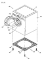
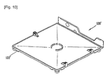
- FIG. 9 is an exploded perspective view showing the base mounted at the washing/drying machine according to FIG. 2 and FIG. 10 is a perspective view showing a variation of the base according to FIG. 9 .
- the height-adjustable legs121 are mounted at four edges of the base 120 and base side coupling ribs 122 are formed at both sides based on the legs 121.
- the base side coupling ribs 122 are provided with coupling holes 123 communicated with the coupling holes 231a formed at the coupling ribs 231 of the supporters 230.
- the supporters 230 are interposed between the washing/drying machine 100 and the pedestal 200 and then coupling means such as screws are mounted in the coupling holes 123, 231 a under a state that the coupling ribs 231 formed at the supporters 230 and the base side coupling ribs 122 are disposed to correspond to each other.
- the coupling ribs 231 of the supporters 230 may be disposed outside and the base side coupling ribs 122 may be disposed inside. And then, the coupling means such as screws are mounted in the coupling holes 123, 231 a thereof so as to couple the coupling ribs 231 and the base side coupling ribs 122. Accordingly, the coupling ribs 122, 231 a are not protruded more than the surface of the washing/drying machine 100 or the pedestal 200, thereby implementing an excellent external appearance. Also, it is not required to use an additional component such as a bracket in order to mount the washing/drying machine 100 or the pedestal 200 at the supporters 230.
- the base 120 may be formed in a honeycomb shape or lattice shape as shown in FIG. 9 , or may be implemented as a planar shape base 120' as shown in FIG. 10 .
- Coupling ribs 122' are respectively formed at a lower surface of the planar shape base 120'.
- the present applicant has explained the washing/drying machine with applying only to a washing machine and a drying machine, however the present invention is not limited thereto.
- the present invention can be applied to various washing/drying machines such as a washing and drying machine, a complex washing system and a refresher having a wrinkle removing function.
- the present invention is applied to a front loading type washing/drying machine in which the laundry is contained from the front side.
- a top loading type washing/drying machine in which the laundry is contained from the upper side is within a scope of the present invention.
Landscapes
- Engineering & Computer Science (AREA)
- Textile Engineering (AREA)
- Main Body Construction Of Washing Machines And Laundry Dryers (AREA)
- Accessory Of Washing/Drying Machine, Commercial Washing/Drying Machine, Other Washing/Drying Machine (AREA)
- Detail Structures Of Washing Machines And Dryers (AREA)
Claims (15)
- Sockel (200) zum Tragen einer Wasch-/Trockenmaschine (100), der aufweist:ein Gehäuse (210) mit einem spezifischen Raum darin;mehrere Träger (230), die an dem Gehäuse (210) montiert sind und die auf dem Gehäuse (210) angeordnete Wasch-/Trockenmaschine (100) tragen; undVerbindungsteile (240), die die an einer Seite des Gehäuses (210) montierten Träger (230) miteinander verbinden, dadurch gekennzeichnet, dassdie Träger (230) an dem Gehäuse (210) befestigt sind und mit Kopplungsrippen (231) zum Befestigen der Wasch-/Trockenmaschine (100) an dem Gehäuse (210) versehen sind, und
die Kopplungsrippen (231) geeignet sind, mit basisseitigen Kopplungsrippen (122) einer Basis gekoppelt zu werden, welche mit einem unteren Ende eines Hauptkörpers (110) der Wasch-/Trockenmaschine (100) gekoppelt sind. - Sockel (200) nach Anspruch 1, wobei die Träger (230) und die Verbindungsteile (240), die an einer Seite des Gehäuses (210) montiert sind, integral ausgebildet sind.
- Sockel (200) nach Anspruch 2, wobei jeder Träger (230) mit einem Beinführungsloch (232), um ein Bein des Objekts aufzunehmen, und einer Abschirmwand (233), um zu verhindern, dass das Bein nach außen freiliegt, versehen ist.
- Sockel (200) nach Anspruch 3, wobei eine Höhe der Abschirmwand (433) gleich wie die des Trägers (230) ist.
- Sockel (200) nach Anspruch 4, wobei das Beinführungsloch (432) teilweise weiter als die Abschirmwand (433) vorsteht.
- Sockel (200) nach Anspruch 3, wobei eine Höhe der Abschirmwand (233) geringer als die des Trägers (200) ist.
- Sockel (200) nach Anspruch 6, wobei das Beinführungsloch (332) teilweise geöffnet ist.
- Sockel (200) nach einem der Ansprüche 3 bis 7, wobei jeder Träger (230) ferner mit mehreren Verstärkungsrippen (235) versehen ist, um die Materialmenge, die benötigt wird, um den Träger (230) herzustellen, zu verringern und die Festigkeit eines Umfangsabschnitts des Beinführungslochs (232) zu verstärken.
- Sockel (200) nach einem der Ansprüche 1 bis 8, wobei die Kopplungsrippen (231) seitlich innerhalb der Seitenoberfläche der Träger (230) angeordnet sind.
- Wasch-/Trockenmaschine (100), die aufweist:einen Wasch-/Trockenmaschinenkörper (110), der einen Wasch- oder Trocknungsbetrieb für Wäsche ausführt;eine Basis (120), die mit einem unteren Ende des Hauptkörpers (110) gekoppelt ist, um den Hauptkörper (110) zu tragen, und die mit Beinen (121) versehen ist; undeinen Sockel (200) nach einem der Ansprüche 1 bis 9, der an einer Unterseite des Hauptkörpers (110) installiert ist und den Hauptkörper (110) trägt,wobei der Sockel (200) eine obere Oberfläche hat, die mit den mehreren Trägem (230) versehen ist, und wobei die Basis mit basisseitigen Kopplungsrippen versehen ist, die mit Kopplungsrippen der Träger gekoppelt sind.
- Wasch-/Trockenmaschine (100) nach Anspruch 10, wobei die Träger (230), die an einer Seite des Sockels (200) montiert sind, und die Verbindungsteile (240) integral ausgebildet sind.
- Wasch-/Trockenmaschine (100) nach einem der Ansprüche 10 bis 11, wobei jeder Träger (230) mit einem Beinführungsloch (232), um das Bein (121) aufzunehmen, und einer Abschirmwand (233), um zu verhindern, dass das Bein nach außen freiliegt, versehen ist.
- Wasch-/Trockenmaschine (100) nach Anspruch 12, wobei das Beinführungsloch (232) teilweise weiter als die Abschirmwand (233) vorsteht.
- Wasch-/Trockenmaschine (100) nach Anspruch 12, wobei das Beinführungsloch (232) teilweise geöffnet ist.
- Wasch-/Trockenmaschine (100) nach Anspruch 12, wobei die Verbindungsteile (240) dazu dienen, eine Lücke zwischen dem Sockel (200) und dem Hauptkörper (110) abzuschirmen.
Applications Claiming Priority (2)
| Application Number | Priority Date | Filing Date | Title |
|---|---|---|---|
| KR1020070089184A KR100925737B1 (ko) | 2007-09-03 | 2007-09-03 | 서포터, 이를 구비한 페데스탈 및 의류처리장치 |
| PCT/KR2008/005187 WO2009031815A2 (en) | 2007-09-03 | 2008-09-03 | Supporter and pedestal and washing/drying machine having the same |
Publications (3)
| Publication Number | Publication Date |
|---|---|
| EP2201168A2 EP2201168A2 (de) | 2010-06-30 |
| EP2201168A4 EP2201168A4 (de) | 2014-08-06 |
| EP2201168B1 true EP2201168B1 (de) | 2016-11-30 |
Family
ID=39479721
Family Applications (1)
| Application Number | Title | Priority Date | Filing Date |
|---|---|---|---|
| EP08793672.0A Not-in-force EP2201168B1 (de) | 2007-09-03 | 2008-09-03 | Unterstützer und sockel sowie damit ausgerüsteter waschtrockner |
Country Status (6)
| Country | Link |
|---|---|
| US (1) | US8506025B2 (de) |
| EP (1) | EP2201168B1 (de) |
| KR (1) | KR100925737B1 (de) |
| CN (2) | CN101187136A (de) |
| AU (1) | AU2008295747B2 (de) |
| WO (1) | WO2009031815A2 (de) |
Families Citing this family (22)
| Publication number | Priority date | Publication date | Assignee | Title |
|---|---|---|---|---|
| KR101422571B1 (ko) * | 2009-10-13 | 2014-07-24 | 삼성전자 주식회사 | 받침대 및 이를 구비한 세탁기 |
| EP2728050B1 (de) * | 2011-12-08 | 2017-06-28 | Dongbu Daewoo Electronics Corporation | Wandmontierte trommelwaschmaschine |
| US9249007B2 (en) * | 2014-05-23 | 2016-02-02 | Buc-ee's Ltd. | Ice machine risers |
| KR101674962B1 (ko) * | 2015-02-16 | 2016-11-10 | 엘지전자 주식회사 | 의류처리장치 |
| US10443180B2 (en) | 2015-02-16 | 2019-10-15 | Lg Electronics Inc. | Laundry treatment apparatus |
| CN104805636B (zh) * | 2015-04-21 | 2018-04-20 | 无锡小天鹅股份有限公司 | 复合式洗衣机组件和洗衣机 |
| WO2016169525A1 (zh) * | 2015-04-21 | 2016-10-27 | 无锡小天鹅股份有限公司 | 复合式洗衣机组件和洗衣机 |
| CN104846598A (zh) * | 2015-04-28 | 2015-08-19 | 无锡小天鹅股份有限公司 | 用于家用电器的底座和具有其的家用电器 |
| CN104846597A (zh) * | 2015-04-28 | 2015-08-19 | 无锡小天鹅股份有限公司 | 用于家用电器的底座和具有其的家用电器 |
| WO2017059907A1 (en) * | 2015-10-08 | 2017-04-13 | Arcelik Anonim Sirketi | Drawer assembly for a laundry machine |
| CN105937172A (zh) * | 2016-06-29 | 2016-09-14 | 无锡小天鹅股份有限公司 | 干衣机 |
| CN107558114B (zh) * | 2016-06-30 | 2020-06-30 | 青岛胶南海尔洗衣机有限公司 | 一种液压调平底座及洗衣机 |
| CN108626527B (zh) | 2017-03-22 | 2021-04-20 | 青岛胶南海尔洗衣机有限公司 | 一种家用电器用底脚及家用电器 |
| CN108625122B (zh) | 2017-03-23 | 2021-03-26 | 青岛胶南海尔洗衣机有限公司 | 一种家用电器用底脚及家用电器 |
| CN108626532B (zh) | 2017-03-23 | 2021-03-30 | 青岛胶南海尔洗衣机有限公司 | 一种家用电器用底脚及家用电器 |
| CN110715141B (zh) * | 2019-10-22 | 2021-03-26 | 华南理工大学 | 一种加固增强型可编程计算机控制器 |
| KR102878614B1 (ko) * | 2020-05-18 | 2025-10-30 | 엘지전자 주식회사 | 의류처리장치 |
| CN112353263B (zh) * | 2020-11-06 | 2021-10-08 | 广东格兰仕集团有限公司 | 一种家用电器 |
| CN113080628B (zh) * | 2021-03-29 | 2023-02-24 | 安徽尚佰智能家居有限公司 | 一种家用存放烘干一体化的智能鞋柜 |
| KR20230099210A (ko) * | 2021-12-27 | 2023-07-04 | 삼성전자주식회사 | 냉장고 |
| CN114869065B (zh) * | 2022-05-24 | 2023-11-14 | 金鹏智能家居有限公司 | 一种自动选衣的智能衣柜 |
| US12546096B2 (en) * | 2024-03-28 | 2026-02-10 | Brio Water Technology, Inc. | Water dispenser riser assembly and system |
Family Cites Families (21)
| Publication number | Priority date | Publication date | Assignee | Title |
|---|---|---|---|---|
| US3212739A (en) * | 1962-12-31 | 1965-10-19 | Sperry Rand Corp | Hold-down |
| JPS567261Y2 (de) * | 1976-09-03 | 1981-02-17 | ||
| US4124958A (en) * | 1977-07-12 | 1978-11-14 | Rufuss Establishment | Spherical junction element for composable display structures |
| JPH09192388A (ja) * | 1996-01-23 | 1997-07-29 | Sanyo Electric Co Ltd | ドラム式洗濯機 |
| DE19838631A1 (de) * | 1998-08-26 | 2000-03-02 | Benjamin Blumenschein | Sockelgestell für Haushaltsgeräte |
| US6126131A (en) * | 1998-10-22 | 2000-10-03 | Tietz; Wayne D. | Pallet for chests and boxes with casters |
| ITMI20010205U1 (it) * | 2001-04-10 | 2002-10-10 | Drake Corp | Dispositivo di supporto per sedie posizionate all'aperto, in particolare su terreni erbosi |
| US7258319B2 (en) * | 2001-09-24 | 2007-08-21 | Sonoco Development, Inc. | Shipping base for appliances |
| KR100776601B1 (ko) * | 2002-12-17 | 2007-11-16 | 삼성전자주식회사 | 받침대 및 이를 구비한 세탁기 |
| KR20040085516A (ko) | 2003-03-31 | 2004-10-08 | 엘지전자 주식회사 | 세탁기용 받침대 |
| KR20040086059A (ko) * | 2003-03-31 | 2004-10-08 | 엘지전자 주식회사 | 세탁기용 받침대 |
| US20040245899A1 (en) * | 2003-06-05 | 2004-12-09 | Cho Han Ki | Washing machine pedestal |
| US7219609B1 (en) * | 2004-01-05 | 2007-05-22 | Diebold Self-Service Systems Division Of Diebold, Incorporated | Apparatus for shipping and installation of ATM |
| CN1683673A (zh) | 2004-04-12 | 2005-10-19 | 乐金电子(天津)电器有限公司 | 洗衣机底座 |
| KR20050118612A (ko) | 2004-06-14 | 2005-12-19 | 삼성전자주식회사 | 세탁기 및 건조기용 받침대 |
| KR101034193B1 (ko) | 2004-06-15 | 2011-05-12 | 삼성전자주식회사 | 세탁기 및 건조기용 받침대 |
| ES2342471T3 (es) * | 2004-06-14 | 2010-07-07 | Samsung Electronics Co., Ltd. | Soporte para maquina lavadora de ropa y aparato secador de ropa. |
| KR20060120936A (ko) | 2005-05-23 | 2006-11-28 | 엘지전자 주식회사 | 세정 장치 |
| DE102006023995A1 (de) * | 2005-05-23 | 2006-12-28 | Lg Electronic Inc. | Wäschebehandlungsvorrichtung |
| DE202005014026U1 (de) * | 2005-09-05 | 2005-11-10 | Wittenbauer, Rudolf, Dipl.-Ing. (FH) | Bausatz für ein Waschmaschinenuntergestell |
| US20070187564A1 (en) * | 2006-02-03 | 2007-08-16 | Mcguire Stephen J | Load bearing and load anchoring, ground to structure foundation pier |
-
2007
- 2007-09-03 KR KR1020070089184A patent/KR100925737B1/ko not_active Expired - Fee Related
- 2007-12-16 CN CNA2007103001364A patent/CN101187136A/zh active Pending
-
2008
- 2008-09-03 CN CN200880105482XA patent/CN101796241B/zh not_active Expired - Fee Related
- 2008-09-03 AU AU2008295747A patent/AU2008295747B2/en not_active Ceased
- 2008-09-03 EP EP08793672.0A patent/EP2201168B1/de not_active Not-in-force
- 2008-09-03 US US12/676,104 patent/US8506025B2/en not_active Expired - Fee Related
- 2008-09-03 WO PCT/KR2008/005187 patent/WO2009031815A2/en not_active Ceased
Non-Patent Citations (1)
| Title |
|---|
| None * |
Also Published As
| Publication number | Publication date |
|---|---|
| KR100925737B1 (ko) | 2009-11-10 |
| WO2009031815A2 (en) | 2009-03-12 |
| AU2008295747B2 (en) | 2011-10-27 |
| CN101187136A (zh) | 2008-05-28 |
| WO2009031815A3 (en) | 2009-05-22 |
| EP2201168A2 (de) | 2010-06-30 |
| CN101796241A (zh) | 2010-08-04 |
| US8506025B2 (en) | 2013-08-13 |
| CN101796241B (zh) | 2012-07-18 |
| KR20090024012A (ko) | 2009-03-06 |
| AU2008295747A1 (en) | 2009-03-12 |
| EP2201168A4 (de) | 2014-08-06 |
| US20100201236A1 (en) | 2010-08-12 |
Similar Documents
| Publication | Publication Date | Title |
|---|---|---|
| AU2008295747B2 (en) | Supporter and pedestal and washing/drying machine having the same | |
| KR100925735B1 (ko) | 서포터, 이를 구비한 키높이 수납장 및 의류처리장치 | |
| EP2063013B1 (de) | Waschmaschine | |
| EP1621660B1 (de) | Tragglied für Waschmaschine oder Trockner | |
| EP2063014B1 (de) | Waschmaschine | |
| CA2707883C (en) | Laundry machine with two washing tubs | |
| US20070119216A1 (en) | Laundry treatment apparatus | |
| EP2065506B1 (de) | Waschmaschine | |
| AU2006221219B2 (en) | Washing machine | |
| RU2660066C1 (ru) | Устройство для обработки белья | |
| ITMI970326A1 (it) | Cerniera per sportello di elettrodomestico particolarmente per macchina di lavaggio e/o ascigatura di biancheria | |
| CN101177884B (zh) | 滚筒式洗衣机 | |
| KR20180089991A (ko) | 의류처리장치 | |
| KR101028503B1 (ko) | 세탁기용 받침대 | |
| RU2402653C2 (ru) | Стиральная машина | |
| KR20060120936A (ko) | 세정 장치 | |
| KR100977565B1 (ko) | 세탁기용 받침대 | |
| KR20170096316A (ko) | 세탁기 및 세탁기의 세제함 | |
| RU2363787C2 (ru) | Стиральная машина | |
| KR100784714B1 (ko) | 세탁기 상부판 고정 장치 | |
| KR20040081298A (ko) | 세탁기용 받침대 | |
| RU2402654C2 (ru) | Стиральная машина | |
| KR20040081558A (ko) | 세탁기용 받침대 | |
| CN115110271A (zh) | 衣物处理设备的箱体及洗烘一体设备 | |
| KR101166194B1 (ko) | 상업용 세탁물 세정장치의 카드 리더기 |
Legal Events
| Date | Code | Title | Description |
|---|---|---|---|
| PUAI | Public reference made under article 153(3) epc to a published international application that has entered the european phase |
Free format text: ORIGINAL CODE: 0009012 |
|
| 17P | Request for examination filed |
Effective date: 20100324 |
|
| AK | Designated contracting states |
Kind code of ref document: A2 Designated state(s): AT BE BG CH CY CZ DE DK EE ES FI FR GB GR HR HU IE IS IT LI LT LU LV MC MT NL NO PL PT RO SE SI SK TR |
|
| AX | Request for extension of the european patent |
Extension state: AL BA MK RS |
|
| DAX | Request for extension of the european patent (deleted) | ||
| A4 | Supplementary search report drawn up and despatched |
Effective date: 20140704 |
|
| RIC1 | Information provided on ipc code assigned before grant |
Ipc: D06F 39/12 20060101AFI20140630BHEP |
|
| GRAP | Despatch of communication of intention to grant a patent |
Free format text: ORIGINAL CODE: EPIDOSNIGR1 |
|
| INTG | Intention to grant announced |
Effective date: 20160819 |
|
| GRAS | Grant fee paid |
Free format text: ORIGINAL CODE: EPIDOSNIGR3 |
|
| GRAA | (expected) grant |
Free format text: ORIGINAL CODE: 0009210 |
|
| AK | Designated contracting states |
Kind code of ref document: B1 Designated state(s): AT BE BG CH CY CZ DE DK EE ES FI FR GB GR HR HU IE IS IT LI LT LU LV MC MT NL NO PL PT RO SE SI SK TR |
|
| REG | Reference to a national code |
Ref country code: CH Ref legal event code: EP Ref country code: GB Ref legal event code: FG4D |
|
| REG | Reference to a national code |
Ref country code: AT Ref legal event code: REF Ref document number: 849908 Country of ref document: AT Kind code of ref document: T Effective date: 20161215 |
|
| REG | Reference to a national code |
Ref country code: IE Ref legal event code: FG4D |
|
| REG | Reference to a national code |
Ref country code: DE Ref legal event code: R096 Ref document number: 602008047666 Country of ref document: DE |
|
| PG25 | Lapsed in a contracting state [announced via postgrant information from national office to epo] |
Ref country code: LV Free format text: LAPSE BECAUSE OF FAILURE TO SUBMIT A TRANSLATION OF THE DESCRIPTION OR TO PAY THE FEE WITHIN THE PRESCRIBED TIME-LIMIT Effective date: 20161130 |
|
| REG | Reference to a national code |
Ref country code: LT Ref legal event code: MG4D |
|
| REG | Reference to a national code |
Ref country code: NL Ref legal event code: MP Effective date: 20161130 |
|
| REG | Reference to a national code |
Ref country code: AT Ref legal event code: MK05 Ref document number: 849908 Country of ref document: AT Kind code of ref document: T Effective date: 20161130 |
|
| PG25 | Lapsed in a contracting state [announced via postgrant information from national office to epo] |
Ref country code: LT Free format text: LAPSE BECAUSE OF FAILURE TO SUBMIT A TRANSLATION OF THE DESCRIPTION OR TO PAY THE FEE WITHIN THE PRESCRIBED TIME-LIMIT Effective date: 20161130 Ref country code: NO Free format text: LAPSE BECAUSE OF FAILURE TO SUBMIT A TRANSLATION OF THE DESCRIPTION OR TO PAY THE FEE WITHIN THE PRESCRIBED TIME-LIMIT Effective date: 20170228 Ref country code: SE Free format text: LAPSE BECAUSE OF FAILURE TO SUBMIT A TRANSLATION OF THE DESCRIPTION OR TO PAY THE FEE WITHIN THE PRESCRIBED TIME-LIMIT Effective date: 20161130 Ref country code: GR Free format text: LAPSE BECAUSE OF FAILURE TO SUBMIT A TRANSLATION OF THE DESCRIPTION OR TO PAY THE FEE WITHIN THE PRESCRIBED TIME-LIMIT Effective date: 20170301 |
|
| PG25 | Lapsed in a contracting state [announced via postgrant information from national office to epo] |
Ref country code: ES Free format text: LAPSE BECAUSE OF FAILURE TO SUBMIT A TRANSLATION OF THE DESCRIPTION OR TO PAY THE FEE WITHIN THE PRESCRIBED TIME-LIMIT Effective date: 20161130 Ref country code: AT Free format text: LAPSE BECAUSE OF FAILURE TO SUBMIT A TRANSLATION OF THE DESCRIPTION OR TO PAY THE FEE WITHIN THE PRESCRIBED TIME-LIMIT Effective date: 20161130 Ref country code: PL Free format text: LAPSE BECAUSE OF FAILURE TO SUBMIT A TRANSLATION OF THE DESCRIPTION OR TO PAY THE FEE WITHIN THE PRESCRIBED TIME-LIMIT Effective date: 20161130 Ref country code: HR Free format text: LAPSE BECAUSE OF FAILURE TO SUBMIT A TRANSLATION OF THE DESCRIPTION OR TO PAY THE FEE WITHIN THE PRESCRIBED TIME-LIMIT Effective date: 20161130 Ref country code: PT Free format text: LAPSE BECAUSE OF FAILURE TO SUBMIT A TRANSLATION OF THE DESCRIPTION OR TO PAY THE FEE WITHIN THE PRESCRIBED TIME-LIMIT Effective date: 20170330 Ref country code: FI Free format text: LAPSE BECAUSE OF FAILURE TO SUBMIT A TRANSLATION OF THE DESCRIPTION OR TO PAY THE FEE WITHIN THE PRESCRIBED TIME-LIMIT Effective date: 20161130 |
|
| PG25 | Lapsed in a contracting state [announced via postgrant information from national office to epo] |
Ref country code: NL Free format text: LAPSE BECAUSE OF FAILURE TO SUBMIT A TRANSLATION OF THE DESCRIPTION OR TO PAY THE FEE WITHIN THE PRESCRIBED TIME-LIMIT Effective date: 20161130 |
|
| PG25 | Lapsed in a contracting state [announced via postgrant information from national office to epo] |
Ref country code: CZ Free format text: LAPSE BECAUSE OF FAILURE TO SUBMIT A TRANSLATION OF THE DESCRIPTION OR TO PAY THE FEE WITHIN THE PRESCRIBED TIME-LIMIT Effective date: 20161130 Ref country code: RO Free format text: LAPSE BECAUSE OF FAILURE TO SUBMIT A TRANSLATION OF THE DESCRIPTION OR TO PAY THE FEE WITHIN THE PRESCRIBED TIME-LIMIT Effective date: 20161130 Ref country code: SK Free format text: LAPSE BECAUSE OF FAILURE TO SUBMIT A TRANSLATION OF THE DESCRIPTION OR TO PAY THE FEE WITHIN THE PRESCRIBED TIME-LIMIT Effective date: 20161130 Ref country code: DK Free format text: LAPSE BECAUSE OF FAILURE TO SUBMIT A TRANSLATION OF THE DESCRIPTION OR TO PAY THE FEE WITHIN THE PRESCRIBED TIME-LIMIT Effective date: 20161130 Ref country code: EE Free format text: LAPSE BECAUSE OF FAILURE TO SUBMIT A TRANSLATION OF THE DESCRIPTION OR TO PAY THE FEE WITHIN THE PRESCRIBED TIME-LIMIT Effective date: 20161130 |
|
| REG | Reference to a national code |
Ref country code: FR Ref legal event code: PLFP Year of fee payment: 10 |
|
| PG25 | Lapsed in a contracting state [announced via postgrant information from national office to epo] |
Ref country code: BE Free format text: LAPSE BECAUSE OF FAILURE TO SUBMIT A TRANSLATION OF THE DESCRIPTION OR TO PAY THE FEE WITHIN THE PRESCRIBED TIME-LIMIT Effective date: 20161130 Ref country code: IT Free format text: LAPSE BECAUSE OF FAILURE TO SUBMIT A TRANSLATION OF THE DESCRIPTION OR TO PAY THE FEE WITHIN THE PRESCRIBED TIME-LIMIT Effective date: 20161130 Ref country code: BG Free format text: LAPSE BECAUSE OF FAILURE TO SUBMIT A TRANSLATION OF THE DESCRIPTION OR TO PAY THE FEE WITHIN THE PRESCRIBED TIME-LIMIT Effective date: 20170228 |
|
| REG | Reference to a national code |
Ref country code: DE Ref legal event code: R097 Ref document number: 602008047666 Country of ref document: DE |
|
| PLBE | No opposition filed within time limit |
Free format text: ORIGINAL CODE: 0009261 |
|
| STAA | Information on the status of an ep patent application or granted ep patent |
Free format text: STATUS: NO OPPOSITION FILED WITHIN TIME LIMIT |
|
| PGFP | Annual fee paid to national office [announced via postgrant information from national office to epo] |
Ref country code: PL Payment date: 20170523 Year of fee payment: 9 |
|
| 26N | No opposition filed |
Effective date: 20170831 |
|
| PG25 | Lapsed in a contracting state [announced via postgrant information from national office to epo] |
Ref country code: SI Free format text: LAPSE BECAUSE OF FAILURE TO SUBMIT A TRANSLATION OF THE DESCRIPTION OR TO PAY THE FEE WITHIN THE PRESCRIBED TIME-LIMIT Effective date: 20161130 |
|
| REG | Reference to a national code |
Ref country code: CH Ref legal event code: PL |
|
| PG25 | Lapsed in a contracting state [announced via postgrant information from national office to epo] |
Ref country code: MC Free format text: LAPSE BECAUSE OF FAILURE TO SUBMIT A TRANSLATION OF THE DESCRIPTION OR TO PAY THE FEE WITHIN THE PRESCRIBED TIME-LIMIT Effective date: 20161130 |
|
| REG | Reference to a national code |
Ref country code: IE Ref legal event code: MM4A |
|
| PG25 | Lapsed in a contracting state [announced via postgrant information from national office to epo] |
Ref country code: LU Free format text: LAPSE BECAUSE OF NON-PAYMENT OF DUE FEES Effective date: 20170903 |
|
| PG25 | Lapsed in a contracting state [announced via postgrant information from national office to epo] |
Ref country code: LI Free format text: LAPSE BECAUSE OF NON-PAYMENT OF DUE FEES Effective date: 20170930 Ref country code: CH Free format text: LAPSE BECAUSE OF NON-PAYMENT OF DUE FEES Effective date: 20170930 Ref country code: IE Free format text: LAPSE BECAUSE OF NON-PAYMENT OF DUE FEES Effective date: 20170903 |
|
| REG | Reference to a national code |
Ref country code: FR Ref legal event code: PLFP Year of fee payment: 11 |
|
| PG25 | Lapsed in a contracting state [announced via postgrant information from national office to epo] |
Ref country code: MT Free format text: LAPSE BECAUSE OF NON-PAYMENT OF DUE FEES Effective date: 20170903 |
|
| GBPC | Gb: european patent ceased through non-payment of renewal fee |
Effective date: 20180903 |
|
| PG25 | Lapsed in a contracting state [announced via postgrant information from national office to epo] |
Ref country code: HU Free format text: LAPSE BECAUSE OF FAILURE TO SUBMIT A TRANSLATION OF THE DESCRIPTION OR TO PAY THE FEE WITHIN THE PRESCRIBED TIME-LIMIT; INVALID AB INITIO Effective date: 20080903 |
|
| PG25 | Lapsed in a contracting state [announced via postgrant information from national office to epo] |
Ref country code: GB Free format text: LAPSE BECAUSE OF NON-PAYMENT OF DUE FEES Effective date: 20180903 Ref country code: CY Free format text: LAPSE BECAUSE OF NON-PAYMENT OF DUE FEES Effective date: 20161130 |
|
| PGFP | Annual fee paid to national office [announced via postgrant information from national office to epo] |
Ref country code: DE Payment date: 20190805 Year of fee payment: 12 Ref country code: FR Payment date: 20190806 Year of fee payment: 12 |
|
| PG25 | Lapsed in a contracting state [announced via postgrant information from national office to epo] |
Ref country code: TR Free format text: LAPSE BECAUSE OF FAILURE TO SUBMIT A TRANSLATION OF THE DESCRIPTION OR TO PAY THE FEE WITHIN THE PRESCRIBED TIME-LIMIT Effective date: 20161130 |
|
| PG25 | Lapsed in a contracting state [announced via postgrant information from national office to epo] |
Ref country code: IS Free format text: LAPSE BECAUSE OF FAILURE TO SUBMIT A TRANSLATION OF THE DESCRIPTION OR TO PAY THE FEE WITHIN THE PRESCRIBED TIME-LIMIT Effective date: 20170330 |
|
| REG | Reference to a national code |
Ref country code: DE Ref legal event code: R119 Ref document number: 602008047666 Country of ref document: DE |
|
| PG25 | Lapsed in a contracting state [announced via postgrant information from national office to epo] |
Ref country code: FR Free format text: LAPSE BECAUSE OF NON-PAYMENT OF DUE FEES Effective date: 20200930 Ref country code: DE Free format text: LAPSE BECAUSE OF NON-PAYMENT OF DUE FEES Effective date: 20210401 |