EP2201227B1 - Scr-system und spülverfahren dafür - Google Patents
Scr-system und spülverfahren dafür Download PDFInfo
- Publication number
- EP2201227B1 EP2201227B1 EP08804147A EP08804147A EP2201227B1 EP 2201227 B1 EP2201227 B1 EP 2201227B1 EP 08804147 A EP08804147 A EP 08804147A EP 08804147 A EP08804147 A EP 08804147A EP 2201227 B1 EP2201227 B1 EP 2201227B1
- Authority
- EP
- European Patent Office
- Prior art keywords
- pump
- suction device
- timer
- purge
- exhaust gases
- Prior art date
- Legal status (The legal status is an assumption and is not a legal conclusion. Google has not performed a legal analysis and makes no representation as to the accuracy of the status listed.)
- Active
Links
Images


Classifications
-
- F—MECHANICAL ENGINEERING; LIGHTING; HEATING; WEAPONS; BLASTING
- F01—MACHINES OR ENGINES IN GENERAL; ENGINE PLANTS IN GENERAL; STEAM ENGINES
- F01N—GAS-FLOW SILENCERS OR EXHAUST APPARATUS FOR MACHINES OR ENGINES IN GENERAL; GAS-FLOW SILENCERS OR EXHAUST APPARATUS FOR INTERNAL-COMBUSTION ENGINES
- F01N3/00—Exhaust or silencing apparatus having means for purifying, rendering innocuous, or otherwise treating exhaust
- F01N3/08—Exhaust or silencing apparatus having means for purifying, rendering innocuous, or otherwise treating exhaust for rendering innocuous
-
- F—MECHANICAL ENGINEERING; LIGHTING; HEATING; WEAPONS; BLASTING
- F01—MACHINES OR ENGINES IN GENERAL; ENGINE PLANTS IN GENERAL; STEAM ENGINES
- F01N—GAS-FLOW SILENCERS OR EXHAUST APPARATUS FOR MACHINES OR ENGINES IN GENERAL; GAS-FLOW SILENCERS OR EXHAUST APPARATUS FOR INTERNAL-COMBUSTION ENGINES
- F01N3/00—Exhaust or silencing apparatus having means for purifying, rendering innocuous, or otherwise treating exhaust
- F01N3/08—Exhaust or silencing apparatus having means for purifying, rendering innocuous, or otherwise treating exhaust for rendering innocuous
- F01N3/10—Exhaust or silencing apparatus having means for purifying, rendering innocuous, or otherwise treating exhaust for rendering innocuous by thermal or catalytic conversion of noxious components of exhaust
- F01N3/18—Exhaust or silencing apparatus having means for purifying, rendering innocuous, or otherwise treating exhaust for rendering innocuous by thermal or catalytic conversion of noxious components of exhaust characterised by methods of operation; Control
- F01N3/20—Exhaust or silencing apparatus having means for purifying, rendering innocuous, or otherwise treating exhaust for rendering innocuous by thermal or catalytic conversion of noxious components of exhaust characterised by methods of operation; Control specially adapted for catalytic conversion
- F01N3/206—Adding periodically or continuously substances to exhaust gases for promoting purification, e.g. catalytic material in liquid form, NOx reducing agents
- F01N3/208—Control of selective catalytic reduction [SCR], e.g. by adjusting the dosing of reducing agent
-
- B—PERFORMING OPERATIONS; TRANSPORTING
- B01—PHYSICAL OR CHEMICAL PROCESSES OR APPARATUS IN GENERAL
- B01D—SEPARATION
- B01D2251/00—Reactants
- B01D2251/20—Reductants
- B01D2251/206—Ammonium compounds
- B01D2251/2067—Urea
-
- B—PERFORMING OPERATIONS; TRANSPORTING
- B01—PHYSICAL OR CHEMICAL PROCESSES OR APPARATUS IN GENERAL
- B01D—SEPARATION
- B01D2257/00—Components to be removed
- B01D2257/40—Nitrogen compounds
- B01D2257/404—Nitrogen oxides other than dinitrogen oxide
-
- F—MECHANICAL ENGINEERING; LIGHTING; HEATING; WEAPONS; BLASTING
- F01—MACHINES OR ENGINES IN GENERAL; ENGINE PLANTS IN GENERAL; STEAM ENGINES
- F01N—GAS-FLOW SILENCERS OR EXHAUST APPARATUS FOR MACHINES OR ENGINES IN GENERAL; GAS-FLOW SILENCERS OR EXHAUST APPARATUS FOR INTERNAL-COMBUSTION ENGINES
- F01N2610/00—Adding substances to exhaust gases
- F01N2610/02—Adding substances to exhaust gases the substance being ammonia or urea
-
- F—MECHANICAL ENGINEERING; LIGHTING; HEATING; WEAPONS; BLASTING
- F01—MACHINES OR ENGINES IN GENERAL; ENGINE PLANTS IN GENERAL; STEAM ENGINES
- F01N—GAS-FLOW SILENCERS OR EXHAUST APPARATUS FOR MACHINES OR ENGINES IN GENERAL; GAS-FLOW SILENCERS OR EXHAUST APPARATUS FOR INTERNAL-COMBUSTION ENGINES
- F01N2610/00—Adding substances to exhaust gases
- F01N2610/14—Arrangements for the supply of substances, e.g. conduits
- F01N2610/1473—Overflow or return means for the substances, e.g. conduits or valves for the return path
-
- F—MECHANICAL ENGINEERING; LIGHTING; HEATING; WEAPONS; BLASTING
- F01—MACHINES OR ENGINES IN GENERAL; ENGINE PLANTS IN GENERAL; STEAM ENGINES
- F01N—GAS-FLOW SILENCERS OR EXHAUST APPARATUS FOR MACHINES OR ENGINES IN GENERAL; GAS-FLOW SILENCERS OR EXHAUST APPARATUS FOR INTERNAL-COMBUSTION ENGINES
- F01N2610/00—Adding substances to exhaust gases
- F01N2610/14—Arrangements for the supply of substances, e.g. conduits
- F01N2610/1493—Purging the reducing agent out of the conduits or nozzle
-
- F—MECHANICAL ENGINEERING; LIGHTING; HEATING; WEAPONS; BLASTING
- F01—MACHINES OR ENGINES IN GENERAL; ENGINE PLANTS IN GENERAL; STEAM ENGINES
- F01N—GAS-FLOW SILENCERS OR EXHAUST APPARATUS FOR MACHINES OR ENGINES IN GENERAL; GAS-FLOW SILENCERS OR EXHAUST APPARATUS FOR INTERNAL-COMBUSTION ENGINES
- F01N2900/00—Details of electrical control or of the monitoring of the exhaust gas treating apparatus
- F01N2900/04—Methods of control or diagnosing
- F01N2900/0422—Methods of control or diagnosing measuring the elapsed time
-
- F—MECHANICAL ENGINEERING; LIGHTING; HEATING; WEAPONS; BLASTING
- F01—MACHINES OR ENGINES IN GENERAL; ENGINE PLANTS IN GENERAL; STEAM ENGINES
- F01N—GAS-FLOW SILENCERS OR EXHAUST APPARATUS FOR MACHINES OR ENGINES IN GENERAL; GAS-FLOW SILENCERS OR EXHAUST APPARATUS FOR INTERNAL-COMBUSTION ENGINES
- F01N2900/00—Details of electrical control or of the monitoring of the exhaust gas treating apparatus
- F01N2900/06—Parameters used for exhaust control or diagnosing
- F01N2900/08—Parameters used for exhaust control or diagnosing said parameters being related to the engine
-
- F—MECHANICAL ENGINEERING; LIGHTING; HEATING; WEAPONS; BLASTING
- F01—MACHINES OR ENGINES IN GENERAL; ENGINE PLANTS IN GENERAL; STEAM ENGINES
- F01N—GAS-FLOW SILENCERS OR EXHAUST APPARATUS FOR MACHINES OR ENGINES IN GENERAL; GAS-FLOW SILENCERS OR EXHAUST APPARATUS FOR INTERNAL-COMBUSTION ENGINES
- F01N2900/00—Details of electrical control or of the monitoring of the exhaust gas treating apparatus
- F01N2900/06—Parameters used for exhaust control or diagnosing
- F01N2900/18—Parameters used for exhaust control or diagnosing said parameters being related to the system for adding a substance into the exhaust
- F01N2900/1806—Properties of reducing agent or dosing system
- F01N2900/1808—Pressure
-
- Y—GENERAL TAGGING OF NEW TECHNOLOGICAL DEVELOPMENTS; GENERAL TAGGING OF CROSS-SECTIONAL TECHNOLOGIES SPANNING OVER SEVERAL SECTIONS OF THE IPC; TECHNICAL SUBJECTS COVERED BY FORMER USPC CROSS-REFERENCE ART COLLECTIONS [XRACs] AND DIGESTS
- Y02—TECHNOLOGIES OR APPLICATIONS FOR MITIGATION OR ADAPTATION AGAINST CLIMATE CHANGE
- Y02T—CLIMATE CHANGE MITIGATION TECHNOLOGIES RELATED TO TRANSPORTATION
- Y02T10/00—Road transport of goods or passengers
- Y02T10/10—Internal combustion engine [ICE] based vehicles
- Y02T10/12—Improving ICE efficiencies
Definitions
- the present application relates to an SCR system and a method for purging such a system.
- One known way to achieve this objective is to use the SCR (Selective Catalytic Reduction) process which enables the reduction of nitrogen oxides by injection of a reducing agent, generally ammonia, into the exhaust line.
- This ammonia may derive from the pyrolytic decomposition of an ammonia precursor solution, whose concentration may be the eutectic concentration.
- Such an ammonia precursor is generally a urea solution.
- the high levels of NO x produced in the engine during combustion at optimized efficiency are treated in a catalyst on exiting the engine.
- This treatment requires the use of the reducing agent at a precise concentration and of extreme quality.
- the solution is thus accurately metered and injected into the exhaust gas stream where it is hydrolysed before converting the nitrogen oxide (NO x ) to nitrogen (N 2 ) and water (H 2 O).
- aqueous urea solution generally used for this purpose eutectic solution containing 32.5 wt% of urea
- freezes at -11°C it is necessary to provide a heating device to liquefy the solution in order to be able to inject it into the exhaust line in the event of starting in freezing conditions.
- Application WO 2006/064028 in the name of the Applicant proposes an SCR system where purging of the line(s) takes place by sucking the exhaust gases through the injector using the pump of the system, which for this purpose either rotates in the opposite direction or is associated with a valve that makes it possible to reverse the flow.
- the advantage of this system is its simplicity and the reduced number of modifications that must be made to it in order to add this function (this is because it suffices to choose a pump that rotates in both directions or to provide a 4-way valve in the system).
- the present invention aims to solve this problem by providing a simple and economic method for purging an SCR system where spraying urea over the catalyst and/or into the silencer of the engine, once the latter is shut off, is avoided.
- the present application relates to an SCR system for treating the exhaust gases of an internal combustion engine, this system comprising a line for feeding the urea solution into the exhaust gases and a pump capable both of feeding the urea solution into said exhaust gases and of purging at least one part of the line by sucking a gas therethrough by means of a suction device, this system also comprising a control unit capable of activating and/or deactivating the operation of the pump and that of the suction device in a sequential manner in the course of one and the same purge procedure, and a timer that enables the pump to be actuated at the end of a predetermined period and/or after the pressure (p) has dropped below a reference value (p ref ), and makes it possible to open and close the suction device.
- a control unit capable of activating and/or deactivating the operation of the pump and that of the suction device in a sequential manner in the course of one and the same purge procedure
- a timer that enables the pump to be actuated at the end of
- SCR system is understood to mean a system for the catalytic reduction of the NO x from the exhaust gases of an internal combustion engine, preferably of a vehicle, using urea as a liquid ammonia precursor.
- the present invention is advantageously applied to diesel engines, and in particular to the diesel engines of vehicles and particularly preferably to the diesel engines of heavy goods vehicles.
- urea is understood to mean any, generally aqueous, solution containing urea.
- the invention gives good results with eutectic water/urea solutions for which there is a quality standard: for example, according to the standard DIN 70070, in the case of the AdBlue ® solution (commercial solution of urea), the urea content is between 31.8% and 33.2% (by weight) (i.e. 32.5 +/-0.7 wt%) hence an available amount of ammonia between 18.0% and 18.8%.
- the invention may also be applied to the urea/ammonium formate mixtures, also in aqueous solution, sold under the trade name Denoxium TM and of which one of the compositions (Denoxium-30) contains an equivalent amount of ammonia to that of the AdBlue ® solution.
- Denoxium TM aqueous solution
- the latter have the advantage of only freezing from -30°C onwards (as opposed to -11°C), but have the disadvantages of corrosion problems linked to the possible release of formic acid.
- the present invention is particularly advantageous in the context of eutectic water/urea solutions.
- SCR systems generally comprise at least one tank for storing the urea solution and also a set of components for feeding this to the exhaust gases and that generally comprises active elements such as a pump, filter, valve(s), urea feed conduits (or even urea return conduits in some cases).
- active elements such as a pump, filter, valve(s), urea feed conduits (or even urea return conduits in some cases).
- the method according to the invention enables these components to be purged by sucking gas through them so as to drive the urea solution that they contain back to the tank.
- this purge is carried out using the feed pump and a device that enables a gas (air or exhaust gas) to be sucked up.
- This device may be an injector or a purge valve.
- the purge procedure starts shortly after the engine is shut off.
- purge procedure is understood to mean the set of operations linked to the purge that are carried out as soon as the engine is shut off, this including an optional control to determine whether or not it is necessary to purge the system. This is because, during short journeys the SCR system may not have started up (because the catalyst was not at the right temperature or because, in freezing weather, the heating of the system was not sufficient to start the pump) and it is then important not to purge the lines since they are empty (having been purged when the engine was shut off previously).
- the SCR system has a connection with the ignition key.
- the status of the engine (running or shut off) is communicated to the system and the purge procedure is started as soon as the engine is shut off using the ignition key.
- the pump of the system according to the invention may be located in the urea tank (with the advantage of forming, with it, a compact and integrated module) or, considering the corrosive environment, be located outside of the urea tank. Its constituent materials will preferably be chosen from corrosion-resistant metals (especially certain grades of stainless steel and aluminium). The use of copper, even for connection components, is undesirable.
- any type of pump may be suitable.
- the Applicant has obtained good results with a rotary positive-displacement pump of the gear pump type and in particular, with such a magnetic drive pump, such as that described in Application FR 0756387 in the name of the Applicant.
- the speed of this pump is preferably driven as described in Application PCT/EP2007/057066 in the name of the Applicant.
- the purge gas (air or exhaust gas) suction device may also be of any known type. It may, for example, be a valve or the injector used for metering. Generally, SCR systems comprise an injector at the end of the feed line. In this case, either the suction valve is located very close to this injector (in order to limit the unpurged length as much as possible and/or to enable air to be sucked through the engine silencer, in which case the valve should be located in the exhaust pipe), or it is the injector itself which acts as a suction device. In practice, it is often sufficient to simply open the injector.
- control unit other than that of the SCR system (for example, by that of the engine)
- the use of a valve or of any other suction device directly controlled by the control unit of the SCR system is generally called for (unless provision is made for a system of communication between the two control units, which is sometimes more complicated and/or undesired).
- the control units mentioned above are generally electronic units or ECUs (Electronic Control Units).
- control unit of the SCR system is such that it makes it possible to activate and/or deactivate the operation of the pump and that of the suction device in a sequential manner.
- the term "operation” is understood to mean operation in purge mode. While it is operating in “purge” mode the pump can either rotate in the reverse direction relative to its normal mode of operation (feed mode), or rotate in the same direction if the system comprises a valve that makes it possible to reverse the flows (e.g. 4-way valve as already mentioned previously).
- the system comprises a valve that makes it possible to reverse the flows (e.g. 4-way valve as already mentioned previously).
- the system in order that the system can be purged effectively: either the pump is capable of rotating in two opposite directions, or the system comprises a 4-way valve that makes it possible to reverse the flow in the line without changing the direction of rotation of the pump.
- the operation of the pump in "purge" mode is only activated a certain time after the pump outlet pressure has dropped below a reference value. This is because, in particular in the case of rotary positive-displacement pumps, the pressure decreases with the motor speed and only becomes low enough when this motor speed is almost at rest.
- This sequenced activation may be carried out using a timer that enables the pump to be actuated at the end of a predetermined period and/or after the pressure (p) has dropped below a reference value (p ref ), and makes it possible to open and close the device used for sucking air through the silencer.
- the SCR system comprises a timer and a pressure sensor capable of measuring the pressure at the pump outlet.
- this measurement is made in real time, i.e. at regular intervals of the order of ms (milliseconds) for example, and the control unit is capable of detecting, in real time, the moment at which this pressure drops below a reference value and, at this moment, of actuating the pump in "purge" mode and of starting the timer which finally runs to the end of a given time interval, allowing the air-suction device to open and close at predetermined times.
- the timer may be used for actuating the pump in "purge" mode at the end of a pre-calibrated interval (which is determined experimentally) after cutting the engine and then allowing the air-suction device to open and close at predetermined times.
- the operation of the pump in "purge" mode is therefore activated before that of the device that enables air or gas to be sucked through the silencer in order to prevent urea from being discharged into the exhaust pipe and/or over the catalyst at the start of the purge (when the lines are full of urea).
- the time between the activation of the pump and that of the suction device is short (typically of the order of ms) in order to avoid generating too high a vacuum in the section of the line located between the pump and the suction device (which could cause it to implode (collapse), especially in the case of lines made of plastic).
- the SCR system according to the invention may comprise a non-return device that prevents liquid from entering into these elements once they have been purged.
- This non-return device is preferably located between the pump and the urea tank, and most particularly preferably at the junction of the purged elements with the tank.
- the pump, said device and a urea filter are combined in a compact module, the filter at least partly surrounding the pump and the non-return device being an integral part of a common housing that surrounds the filter and at least one part of the pump.
- This compact module is preferably integrated into a immerged base plate in the liquid tank and the common housing comprises a cover and a lower part such that:
- This cover has the shape of a bell having at least one opening in its lower part and it is positioned so as to create an annular cavity between its inner surface and the outer surface of the enclosure/filter where the liquid can be sucked up through its lower opening.
- the aforementioned timer is advantageous for the aforementioned timer to be capable of deactivating the operation of the pump before that of the suction device (typically a few ms before). This is because, in the opposite case, the pump would be capable of creating a vacuum in the section of line connecting it to the suction device and this section could then fill with liquid once the pump stops, despite the presence of the non-return device.
- the period of time that the pump operates in "purge” mode is preferably long enough to purge all the liquid between the injector and the non-return device. In the variant with a bell-shaped cover described above, this period of time is preferably long enough to discharge all the liquid present in the system including under the bell (so as to keep the filter dry). This period of time varies from one system to another depending, in particular, on the length of the lines. These values are determined during calibrations (prior tests).
- the present invention also relates to a method for purging an SCR system comprising a pump both for feeding a urea solution into said exhaust gases and for purging the system by sucking a gas therethrough by means of a suction device, according to which the operation of the pump and that of the suction device are activated and/or deactivated in a sequential manner in the course of one and the same purge procedure.
- the method uses a "real time" electronic control system.
- a system capable of responding to given events in set periods of time.
- the purge procedure comprises, successively and in order, the following steps:
- Detection of whether or not the pump has operated may be carried out, for example, by automatically setting a parameter to "1" when the engine has run under normal temperature conditions and by setting it to "1" under freezing conditions only if the engine has run for a long enough period for the system to be hot and for the pump to have been able to start.
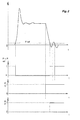
- Figure 1 consists of a block diagram of a process according to several variants of the present invention applied to a suitable SCR system; and Figure 2 illustrates the change in pressure at the outlet of a gear pump and the logic that results therefrom in an SCR system.
- the process illustrated in Figure 1 can be applied to an SCR system comprising a feed pump; a sensor of the pressure at its outlet; an electronic control unit (ECU) driven by a real-time system using a single timer; and a valve for sucking up air and/or exhaust gases.
- ECU electronice control unit
- This process is initiated by the detection of contact with the vehicle engine being cut (KO or Key Off). This therefore causes the purge procedure to be started (EPM or Enable Purge Mode).
- the suction valve is opened (OV or Open Valve).
- the lower figures represent the logic of the phenomenon: the first illustrates, in a boolean manner, the event “pressure below the reference value” (p ⁇ p ref); the second, the event “contact broken” (KO or Key Off); and the third, the event “starting of the pump in purge mode” (SP or Start Purge).
- the way the pump can be controlled to either feed the solution, to be stopped or to function in purge mode can be as described in application WO 2008/087143 in the name of the Applicant.
- the method for controlling the pump described in that document uses a single PWM signal having a duty cycle that varies in function of the desired operation conditions for the pump.
- the pump controller in the embodiment pictured in the figure of that application, the pump controller constituteed a speed controller and a PID regulator in order to adapt the speed of the pump to the desired output pressure.
- Figure 3 shows another embodiment of that method, applying the same idea of sending a single PWM signal to the pump controller, but where said controller only integrates the speed regulator, the PID regulator (or even preferably: a PI regulator) being integrated into the ECM.
- the PID regulator or even preferably: a PI regulator
- the ECM is able of receiving 4 signals: a stop signal (ST), a reverse mode signal (R), a working (measured) pressure signal (MP) and a reference pressure signal (RP).
- the PI(D) regulator which is integrated into it, compares the 2 last signals (MP, RP) and emits a PWM signal giving a rotational speed information (RS) on a scale from 0 to 100 corresponding respectively to the minimum and maximum rotational speed of the pump.
- the ECM then computes the (ST), (R) and (RS) signals into one single PWM signal (PWMCmd) which instructs the pump to either stop, rotate in reverse mode or rotate in forward mode at a given speed.
- the ECM only receives 3 signals (ST, R and reference pressure) and these are directly computed in the PWM signal sent to the pump controller.
Landscapes
- Engineering & Computer Science (AREA)
- Chemical & Material Sciences (AREA)
- Chemical Kinetics & Catalysis (AREA)
- Combustion & Propulsion (AREA)
- Mechanical Engineering (AREA)
- General Engineering & Computer Science (AREA)
- Health & Medical Sciences (AREA)
- Toxicology (AREA)
- Exhaust Gas After Treatment (AREA)
- Treating Waste Gases (AREA)
Claims (8)
- SCR-System zur Behandlung der Abgase eines Verbrennungsmotors, wobei dieses System eine Leitung zur Zufuhr der Harnstofflösung in die Abgase und eine Pumpe, die sowohl die Harnstofflösung in die Abgase zuführen kann als auch mindestens einen Teil der Leitung spülen kann, indem sie mittels einer Saugvorrichtung ein Gas dort hindurch saugt, umfasst, wobei dieses System weiterhin eine Steuereinheit umfasst, die den Betrieb der Pumpe und den der Saugvorrichtung sequenziell im Laufe ein und desselben Spülvorgangs aktivieren und/oder deaktivieren kann,
dadurch gekennzeichnet, dass es ein Zeitglied umfasst, das es der Pumpe ermöglicht, am Ende eines vorbestimmten Zeitraums und/oder nach Abfall des Drucks (p) unter einen Referenzwert (pref) betätigt zu werden, und es ermöglicht, die Saugvorrichtung zu öffnen und zu schließen. - System nach dem vorhergehenden Anspruch, dadurch gekennzeichnet, dass Abschalten des Motors die Spülung nach einem bestimmten Zeitraum aktiviert.
- System nach einem der vorhergehenden Ansprüche, dadurch gekennzeichnet, dass die Pumpe eine Drehkolben-Verdrängerpumpe der Zahnradpumpenart ist.
- System nach einem der vorhergehenden Ansprüche, dadurch gekennzeichnet, dass es ein Einspritzventil zum Einspritzen von Harnstofflösung in die Abgase umfasst und dass die Saugvorrichtung entweder ein nahe dem Einspritzventil positioniertes Ventil ist, das Luft und/oder Abgase ansaugen kann, oder aus dem Einspritzventil selbst besteht.
- System nach einem der vorhergehenden Ansprüche, dadurch gekennzeichnet, dass entweder die Pumpe sich in zwei entgegengesetzte Richtung drehen kann oder das System ein 4-Wege-Ventil umfasst, das es ermöglicht, den Strom in der Leitung umzudrehen, ohne die Drehrichtung der Pumpe zu ändern.
- System nach einem der vorhergehenden Ansprüche, dadurch gekennzeichnet, dass entweder das System einen Drucksensor umfasst, der den Druck am Pumpenauslass messen kann, und das Zeitglied gestartet und die Pumpe im "Spül"-Modus betätigt wird, sobald der Druck (p) unter einen Referenzwert (pref) abfällt; oder das Zeitglied gestartet wird, sobald der Motor abgeschaltet wird und die Pumpe im "Spül"-Modus am Ende eines vorkalibrierten Intervalls betätigt wird; und dass das Zeitglied der Saugvorrichtung gestattet, sich zu vorbestimmten Zeiten nach Betätigung der Pumpe zu öffnen und zu schließen.
- System nach dem vorhergehenden Anspruch, dadurch gekennzeichnet, dass das Zeitglied es ermöglicht, den Betrieb der Pumpe vor dem der Saugvorrichtung zu deaktivieren.
- Verfahren zum Spülen eines SCR-Systems, das eine Leitung zur Zufuhr der Harnstofflösung in die Abgase und eine Pumpe, die sowohl die Harnstofflösung in die Abgase zuführen kann als auch mindestens einen Teil der Leitung spülen kann, indem sie mittels einer Saugvorrichtung ein Gas dort hindurch saugt, umfasst, wobei gemäß dem Verfahren der Betrieb der Pumpe und der der Saugvorrichtung unter Verwendung eines elektronischen "Echtzeit"-Steuersystems sequenziell im Laufe ein und desselben Spülvorgangs aktiviert und/oder deaktiviert wird, dadurch gekennzeichnet, dass der Spülvorgang aufeinander folgend und in Reihenfolge die folgenden Schritte umfasst:1. Erfassen der Motorabschaltung;2. Überprüfen, ob die Pumpe in Betrieb war, während der Motor lief;3. wenn die Pumpe nicht in Betrieb war, Anhalten des Vorgangs;3. wenn die Pumpe in Betrieb war, weiteres Durchführen des Vorgangs aufeinander folgend und in Reihenfolge mit den folgenden Schritten:4'. Messen des Drucks am Pumpenauslass, und wenn er unter einem Referenzwert (pref) liegt, Starten eines Zeitglieds (t=0),5'. wenn das Zeitglied das Ende eines vorbestimmten Zeitintervalls (t1) erfasst, Drehen der Pumpe im Spülmodus;6'. wenn das Zeitglied das Ende eines vorbestimmten Zeitintervalls (t1+t2) erfasst, Öffnen der Saugvorrichtung;7'. wenn das Zeitglied das Ende eines vorbestimmten Zeitintervalls (t1+t2+t3) erfasst, Anhalten der Pumpe;8'. wenn das Zeitglied das Ende eines vorbestimmten Zeitintervalls (t1-t2+t3+t4) erfasst, Schließen der Saugvorrichtung.
Applications Claiming Priority (2)
| Application Number | Priority Date | Filing Date | Title |
|---|---|---|---|
| FR0757602A FR2921105A1 (fr) | 2007-09-14 | 2007-09-14 | Systeme scr et methode pour sa purge |
| PCT/EP2008/062184 WO2009034176A1 (en) | 2007-09-14 | 2008-09-12 | Scr system and method for the purging thereof |
Publications (2)
| Publication Number | Publication Date |
|---|---|
| EP2201227A1 EP2201227A1 (de) | 2010-06-30 |
| EP2201227B1 true EP2201227B1 (de) | 2011-11-09 |
Family
ID=39247149
Family Applications (1)
| Application Number | Title | Priority Date | Filing Date |
|---|---|---|---|
| EP08804147A Active EP2201227B1 (de) | 2007-09-14 | 2008-09-12 | Scr-system und spülverfahren dafür |
Country Status (7)
| Country | Link |
|---|---|
| US (2) | US8393144B2 (de) |
| EP (1) | EP2201227B1 (de) |
| KR (1) | KR101513757B1 (de) |
| CN (1) | CN101809257B (de) |
| AT (1) | ATE532951T1 (de) |
| FR (1) | FR2921105A1 (de) |
| WO (1) | WO2009034176A1 (de) |
Families Citing this family (17)
| Publication number | Priority date | Publication date | Assignee | Title |
|---|---|---|---|---|
| JPWO2010119711A1 (ja) * | 2009-04-13 | 2012-10-22 | ボッシュ株式会社 | 車両用の排気浄化装置 |
| DE102010004201A1 (de) * | 2010-01-08 | 2011-07-14 | Emitec Gesellschaft für Emissionstechnologie mbH, 53797 | Verfahren zum Betrieb einer Fördervorrichtung für ein Reduktionsmittel |
| FR2958681B1 (fr) | 2010-04-13 | 2012-05-25 | Peugeot Citroen Automobiles Sa | Strategie de pilotage de phase de purge sur systeme de reduction catalytique selective |
| FR2967464B1 (fr) | 2010-11-16 | 2012-11-02 | Peugeot Citroen Automobiles Sa | Methode de controle de l'activation d'un systeme de reduction catalytique selective |
| FR2981689B1 (fr) * | 2011-10-21 | 2014-12-26 | Peugeot Citroen Automobiles Sa | Procede de purge d'un systeme d'injection dosee d'un agent liquide dans un ensemble et systeme d'injection pouvant etre purge par un tel procede |
| JP5549709B2 (ja) * | 2012-07-02 | 2014-07-16 | トヨタ自動車株式会社 | 内燃機関の排気浄化装置 |
| JP5995665B2 (ja) * | 2012-11-09 | 2016-09-21 | ボッシュ株式会社 | 還元剤供給装置 |
| DE102013105710B4 (de) * | 2013-06-04 | 2025-05-28 | Schaeffler Technologies AG & Co. KG | Verfahren zum Betrieb einer Vorrichtung zur Förderung einer Flüssigkeit |
| DE102013105712B4 (de) * | 2013-06-04 | 2025-08-07 | Schaeffler Technologies AG & Co. KG | Verfahren zum Betrieb einer Vorrichtung zur Förderung einer Flüssigkeit |
| US9664084B2 (en) | 2015-09-22 | 2017-05-30 | Caterpillar Inc. | Emission reduction system |
| JP6369484B2 (ja) * | 2016-02-17 | 2018-08-08 | トヨタ自動車株式会社 | 内燃機関の排気浄化装置 |
| CN108625939A (zh) * | 2017-03-20 | 2018-10-09 | 天纳克(苏州)排放系统有限公司 | 集成装置、尾气后处理系统以及控制方法 |
| CN110295974B (zh) * | 2018-03-21 | 2022-02-25 | 罗伯特·博世有限公司 | 车辆scr系统及其控制单元和排空控制方法 |
| US11040308B2 (en) | 2018-07-05 | 2021-06-22 | Cummins Emission Solutions Inc. | Systems and methods for purging reductant from a reductant injector |
| CN111828148B (zh) * | 2019-04-15 | 2021-10-26 | 康明斯排放处理公司 | 用于检测未完成清除事件的系统和方法 |
| US11143074B2 (en) | 2019-07-30 | 2021-10-12 | Delphi Technologies Ip Limited | Reagent dosing system and method |
| DE102020215263B4 (de) * | 2020-12-03 | 2023-10-19 | Vitesco Technologies GmbH | Verfahren zur Dosierung einer wässrigen Harnstofflösung |
Family Cites Families (29)
| Publication number | Priority date | Publication date | Assignee | Title |
|---|---|---|---|---|
| EP0400796B1 (de) | 1989-05-30 | 1994-03-16 | Ford Motor Company Limited | Nichtreflektierender Belag, der Fluoride von Leichtmetall enthält |
| JP3017601B2 (ja) | 1992-06-15 | 2000-03-13 | トヨタ自動車株式会社 | 内燃機関の排気浄化装置 |
| WO1996008639A1 (de) * | 1994-09-13 | 1996-03-21 | Siemens Aktiengesellschaft | Verfahren und einrichtung zum einbringen von flüssigkeit in eine abgasreinigungsvorrichtung |
| US6063350A (en) * | 1997-04-02 | 2000-05-16 | Clean Diesel Technologies, Inc. | Reducing nox emissions from an engine by temperature-controlled urea injection for selective catalytic reduction |
| DE10047531A1 (de) * | 2000-09-22 | 2002-04-18 | Bosch Gmbh Robert | Vorrichtung zur Dosierung eines Reduktionsmittels |
| DE10047516A1 (de) * | 2000-09-22 | 2002-04-18 | Bosch Gmbh Robert | Verfahren und Vorrichtung zur Dosierung eines Reduktionsmittels zur Entfernung von Stickoxiden aus Abgasen |
| US20050252201A1 (en) | 2004-05-17 | 2005-11-17 | Lecea Oscar A | Method and apparatus for reducing NOx emissions |
| DE102004030441A1 (de) * | 2004-06-24 | 2006-01-12 | Robert Bosch Gmbh | Dosierventilanordnung sowie Verfahren zum Betreiben einer Dosierventilanordnung |
| DE102004054238A1 (de) * | 2004-11-10 | 2006-05-11 | Robert Bosch Gmbh | Dosiersystem sowie Verfahren zum Betreiben eines Dosiersystems |
| FR2879239A1 (fr) * | 2004-12-15 | 2006-06-16 | Inergy Automotive Systems Res | Systeme de stockage et d'injection d'un additif dans des gaz d'echappement d'un moteur |
| DE502004005576D1 (de) * | 2004-12-30 | 2008-01-03 | Grundfos Nonox As | Vorrichtung zur Erzeugung eines Reduktionsmittel-Luft-Gemisches |
| DE102006007554A1 (de) * | 2006-02-16 | 2007-08-23 | Hydraulik-Ring Gmbh | Förderpumpe, insbesondere für Harnstoffwasserlösung als Abgasnachbehandlungsmedium |
| WO2007141312A1 (en) * | 2006-06-08 | 2007-12-13 | Inergy Automotive Systems Research (Société Anonyme) | Engine exhaust gas additive storage system |
| JP4799289B2 (ja) * | 2006-06-26 | 2011-10-26 | Udトラックス株式会社 | エンジンの排気浄化装置 |
| US20090205316A1 (en) | 2006-07-13 | 2009-08-20 | Inergy Automotive Systems Research (Societe Anonyme) | System and processes for storing an additive and injecting it into the exhaust gases of an engine |
| US20080034733A1 (en) * | 2006-08-14 | 2008-02-14 | Miller Robert L | Fuel supply component purging system |
| JP2008151094A (ja) * | 2006-12-20 | 2008-07-03 | Aisan Ind Co Ltd | 内燃機関の排気浄化装置 |
| DE102006061731A1 (de) * | 2006-12-28 | 2008-07-03 | Robert Bosch Gmbh | Dosiervorrichtung für Flüssig-Reduktionsmittel |
| FR2911643B1 (fr) | 2007-01-19 | 2009-03-13 | Inergy Automotive Systems Res | Methode et systeme de controle du fonctionnement d'une pompe |
| DE102007017459B4 (de) * | 2007-04-03 | 2018-06-14 | Robert Bosch Gmbh | Verfahren zur Dosierung von Reduktionsmittel zum Abgas eines Verbrennungsmotors und Steuergerät |
| WO2008143828A1 (en) * | 2007-05-14 | 2008-11-27 | Clyde Meriwether Smith | Systems and methods for supplying and/or dispensing fluid |
| FR2918718B1 (fr) | 2007-07-10 | 2013-06-28 | Inergy Automotive Systems Res | Pompe rotative pour vehicule. |
| FR2918576B1 (fr) | 2007-07-10 | 2009-10-09 | Inergy Automotive Systems Res | Systeme d'alimentation d'un liquide pour vehicule et module pompe/filtre integre. |
| JP4325725B2 (ja) * | 2008-02-14 | 2009-09-02 | トヨタ自動車株式会社 | 内燃機関の尿素水供給装置 |
| JP5326461B2 (ja) * | 2008-09-22 | 2013-10-30 | マツダ株式会社 | エンジンの排気浄化装置 |
| US8234854B2 (en) * | 2008-10-22 | 2012-08-07 | Caterpillar Inc. | System and method for heating a reducing agent associated with a reducing agent distribution system |
| US8459012B2 (en) * | 2008-11-19 | 2013-06-11 | Caterpillar Inc. | Method for purging a dosing system |
| US8312863B2 (en) * | 2010-03-11 | 2012-11-20 | Caterpillar Inc. | Fuel delivery system for selectively providing fuel to various engine components |
| US8505371B2 (en) * | 2011-11-30 | 2013-08-13 | Ford Global Technologies, Llc | Methods for an exhaust fluid sensor |
-
2007
- 2007-09-14 FR FR0757602A patent/FR2921105A1/fr not_active Withdrawn
-
2008
- 2008-09-12 KR KR1020107007766A patent/KR101513757B1/ko active Active
- 2008-09-12 EP EP08804147A patent/EP2201227B1/de active Active
- 2008-09-12 WO PCT/EP2008/062184 patent/WO2009034176A1/en not_active Ceased
- 2008-09-12 US US12/676,653 patent/US8393144B2/en active Active
- 2008-09-12 AT AT08804147T patent/ATE532951T1/de active
- 2008-09-12 CN CN2008801094579A patent/CN101809257B/zh active Active
-
2013
- 2013-01-14 US US13/740,895 patent/US8959899B2/en active Active
Also Published As
| Publication number | Publication date |
|---|---|
| CN101809257A (zh) | 2010-08-18 |
| KR101513757B1 (ko) | 2015-04-21 |
| US8959899B2 (en) | 2015-02-24 |
| WO2009034176A1 (en) | 2009-03-19 |
| ATE532951T1 (de) | 2011-11-15 |
| FR2921105A1 (fr) | 2009-03-20 |
| EP2201227A1 (de) | 2010-06-30 |
| CN101809257B (zh) | 2012-10-03 |
| KR20100083141A (ko) | 2010-07-21 |
| US20100307142A1 (en) | 2010-12-09 |
| US8393144B2 (en) | 2013-03-12 |
| US20130263580A1 (en) | 2013-10-10 |
Similar Documents
| Publication | Publication Date | Title |
|---|---|---|
| US8959899B2 (en) | SCR system and method for the purging thereof | |
| EP2034148B1 (de) | Motorabgasreinigungsvorrichtung | |
| US7743605B2 (en) | Exhaust emission purifying apparatus for engine | |
| JP5864432B2 (ja) | 還元剤の送給装置の作動方法 | |
| JP5671840B2 (ja) | Scr解凍制御システム | |
| US8096112B2 (en) | Exhaust after-treatment system having a secondary tank | |
| EP2419611B1 (de) | System und vorrichtung zum lagern eines additivs und zu seinem einspritzen in die abgase eines motors | |
| JP6163552B2 (ja) | エア駆動還元剤輸送システム | |
| KR100697545B1 (ko) | 환원제를 계량하기 위한 방법 | |
| EP2158382A1 (de) | Startverfahren für eine pumpe | |
| US10844768B2 (en) | Abnormality determination device | |
| CN101809258A (zh) | 使用电阻性加热元件加热scr系统的方法 | |
| JP2010037979A (ja) | 排気浄化装置 | |
| JP4706627B2 (ja) | エンジンの排気浄化装置 | |
| US8359914B2 (en) | Procedure for checking the functionality of a pump | |
| JP2014218973A (ja) | 内燃機関の排気浄化装置 | |
| CN113606018B (zh) | 尿素溶液反抽控制装置及其故障诊断方法 | |
| JP5617342B2 (ja) | Scrシステム | |
| JP2024073374A (ja) | Scr供給システムを空にする方法 | |
| US20130047581A1 (en) | Reagent Dosing System | |
| CN118517323A (zh) | 用于避免至少部分堵塞scr供应系统的方法 |
Legal Events
| Date | Code | Title | Description |
|---|---|---|---|
| PUAI | Public reference made under article 153(3) epc to a published international application that has entered the european phase |
Free format text: ORIGINAL CODE: 0009012 |
|
| 17P | Request for examination filed |
Effective date: 20100414 |
|
| AK | Designated contracting states |
Kind code of ref document: A1 Designated state(s): AT BE BG CH CY CZ DE DK EE ES FI FR GB GR HR HU IE IS IT LI LT LU LV MC MT NL NO PL PT RO SE SI SK TR |
|
| AX | Request for extension of the european patent |
Extension state: AL BA MK RS |
|
| 17Q | First examination report despatched |
Effective date: 20100913 |
|
| DAX | Request for extension of the european patent (deleted) | ||
| GRAP | Despatch of communication of intention to grant a patent |
Free format text: ORIGINAL CODE: EPIDOSNIGR1 |
|
| GRAS | Grant fee paid |
Free format text: ORIGINAL CODE: EPIDOSNIGR3 |
|
| RIN1 | Information on inventor provided before grant (corrected) |
Inventor name: LEONARD, STEPHANE Inventor name: PEUCAT, FREDERIC Inventor name: DURET, NICOLAS Inventor name: HABUMUREMYI, JEAN-CLAUDE Inventor name: ZELLER, GUILLAUME |
|
| GRAA | (expected) grant |
Free format text: ORIGINAL CODE: 0009210 |
|
| AK | Designated contracting states |
Kind code of ref document: B1 Designated state(s): AT BE BG CH CY CZ DE DK EE ES FI FR GB GR HR HU IE IS IT LI LT LU LV MC MT NL NO PL PT RO SE SI SK TR |
|
| REG | Reference to a national code |
Ref country code: GB Ref legal event code: FG4D |
|
| REG | Reference to a national code |
Ref country code: CH Ref legal event code: EP |
|
| REG | Reference to a national code |
Ref country code: IE Ref legal event code: FG4D |
|
| REG | Reference to a national code |
Ref country code: DE Ref legal event code: R096 Ref document number: 602008011295 Country of ref document: DE Effective date: 20120119 |
|
| REG | Reference to a national code |
Ref country code: NL Ref legal event code: VDEP Effective date: 20111109 |
|
| LTIE | Lt: invalidation of european patent or patent extension |
Effective date: 20111109 |
|
| PG25 | Lapsed in a contracting state [announced via postgrant information from national office to epo] |
Ref country code: NO Free format text: LAPSE BECAUSE OF FAILURE TO SUBMIT A TRANSLATION OF THE DESCRIPTION OR TO PAY THE FEE WITHIN THE PRESCRIBED TIME-LIMIT Effective date: 20120209 Ref country code: LT Free format text: LAPSE BECAUSE OF FAILURE TO SUBMIT A TRANSLATION OF THE DESCRIPTION OR TO PAY THE FEE WITHIN THE PRESCRIBED TIME-LIMIT Effective date: 20111109 Ref country code: IS Free format text: LAPSE BECAUSE OF FAILURE TO SUBMIT A TRANSLATION OF THE DESCRIPTION OR TO PAY THE FEE WITHIN THE PRESCRIBED TIME-LIMIT Effective date: 20120309 |
|
| PG25 | Lapsed in a contracting state [announced via postgrant information from national office to epo] |
Ref country code: GR Free format text: LAPSE BECAUSE OF FAILURE TO SUBMIT A TRANSLATION OF THE DESCRIPTION OR TO PAY THE FEE WITHIN THE PRESCRIBED TIME-LIMIT Effective date: 20120210 Ref country code: BE Free format text: LAPSE BECAUSE OF FAILURE TO SUBMIT A TRANSLATION OF THE DESCRIPTION OR TO PAY THE FEE WITHIN THE PRESCRIBED TIME-LIMIT Effective date: 20111109 Ref country code: NL Free format text: LAPSE BECAUSE OF FAILURE TO SUBMIT A TRANSLATION OF THE DESCRIPTION OR TO PAY THE FEE WITHIN THE PRESCRIBED TIME-LIMIT Effective date: 20111109 Ref country code: LV Free format text: LAPSE BECAUSE OF FAILURE TO SUBMIT A TRANSLATION OF THE DESCRIPTION OR TO PAY THE FEE WITHIN THE PRESCRIBED TIME-LIMIT Effective date: 20111109 Ref country code: SE Free format text: LAPSE BECAUSE OF FAILURE TO SUBMIT A TRANSLATION OF THE DESCRIPTION OR TO PAY THE FEE WITHIN THE PRESCRIBED TIME-LIMIT Effective date: 20111109 Ref country code: SI Free format text: LAPSE BECAUSE OF FAILURE TO SUBMIT A TRANSLATION OF THE DESCRIPTION OR TO PAY THE FEE WITHIN THE PRESCRIBED TIME-LIMIT Effective date: 20111109 Ref country code: PT Free format text: LAPSE BECAUSE OF FAILURE TO SUBMIT A TRANSLATION OF THE DESCRIPTION OR TO PAY THE FEE WITHIN THE PRESCRIBED TIME-LIMIT Effective date: 20120309 Ref country code: HR Free format text: LAPSE BECAUSE OF FAILURE TO SUBMIT A TRANSLATION OF THE DESCRIPTION OR TO PAY THE FEE WITHIN THE PRESCRIBED TIME-LIMIT Effective date: 20111109 Ref country code: PL Free format text: LAPSE BECAUSE OF FAILURE TO SUBMIT A TRANSLATION OF THE DESCRIPTION OR TO PAY THE FEE WITHIN THE PRESCRIBED TIME-LIMIT Effective date: 20111109 |
|
| PG25 | Lapsed in a contracting state [announced via postgrant information from national office to epo] |
Ref country code: CY Free format text: LAPSE BECAUSE OF FAILURE TO SUBMIT A TRANSLATION OF THE DESCRIPTION OR TO PAY THE FEE WITHIN THE PRESCRIBED TIME-LIMIT Effective date: 20111109 |
|
| PG25 | Lapsed in a contracting state [announced via postgrant information from national office to epo] |
Ref country code: EE Free format text: LAPSE BECAUSE OF FAILURE TO SUBMIT A TRANSLATION OF THE DESCRIPTION OR TO PAY THE FEE WITHIN THE PRESCRIBED TIME-LIMIT Effective date: 20111109 Ref country code: DK Free format text: LAPSE BECAUSE OF FAILURE TO SUBMIT A TRANSLATION OF THE DESCRIPTION OR TO PAY THE FEE WITHIN THE PRESCRIBED TIME-LIMIT Effective date: 20111109 Ref country code: SK Free format text: LAPSE BECAUSE OF FAILURE TO SUBMIT A TRANSLATION OF THE DESCRIPTION OR TO PAY THE FEE WITHIN THE PRESCRIBED TIME-LIMIT Effective date: 20111109 Ref country code: BG Free format text: LAPSE BECAUSE OF FAILURE TO SUBMIT A TRANSLATION OF THE DESCRIPTION OR TO PAY THE FEE WITHIN THE PRESCRIBED TIME-LIMIT Effective date: 20120209 Ref country code: CZ Free format text: LAPSE BECAUSE OF FAILURE TO SUBMIT A TRANSLATION OF THE DESCRIPTION OR TO PAY THE FEE WITHIN THE PRESCRIBED TIME-LIMIT Effective date: 20111109 |
|
| PG25 | Lapsed in a contracting state [announced via postgrant information from national office to epo] |
Ref country code: RO Free format text: LAPSE BECAUSE OF FAILURE TO SUBMIT A TRANSLATION OF THE DESCRIPTION OR TO PAY THE FEE WITHIN THE PRESCRIBED TIME-LIMIT Effective date: 20111109 Ref country code: IT Free format text: LAPSE BECAUSE OF FAILURE TO SUBMIT A TRANSLATION OF THE DESCRIPTION OR TO PAY THE FEE WITHIN THE PRESCRIBED TIME-LIMIT Effective date: 20111109 |
|
| PLBE | No opposition filed within time limit |
Free format text: ORIGINAL CODE: 0009261 |
|
| STAA | Information on the status of an ep patent application or granted ep patent |
Free format text: STATUS: NO OPPOSITION FILED WITHIN TIME LIMIT |
|
| REG | Reference to a national code |
Ref country code: AT Ref legal event code: MK05 Ref document number: 532951 Country of ref document: AT Kind code of ref document: T Effective date: 20111109 |
|
| 26N | No opposition filed |
Effective date: 20120810 |
|
| REG | Reference to a national code |
Ref country code: DE Ref legal event code: R097 Ref document number: 602008011295 Country of ref document: DE Effective date: 20120810 |
|
| PG25 | Lapsed in a contracting state [announced via postgrant information from national office to epo] |
Ref country code: AT Free format text: LAPSE BECAUSE OF FAILURE TO SUBMIT A TRANSLATION OF THE DESCRIPTION OR TO PAY THE FEE WITHIN THE PRESCRIBED TIME-LIMIT Effective date: 20111109 |
|
| PG25 | Lapsed in a contracting state [announced via postgrant information from national office to epo] |
Ref country code: MC Free format text: LAPSE BECAUSE OF NON-PAYMENT OF DUE FEES Effective date: 20120930 Ref country code: ES Free format text: LAPSE BECAUSE OF FAILURE TO SUBMIT A TRANSLATION OF THE DESCRIPTION OR TO PAY THE FEE WITHIN THE PRESCRIBED TIME-LIMIT Effective date: 20120220 |
|
| REG | Reference to a national code |
Ref country code: CH Ref legal event code: PL |
|
| GBPC | Gb: european patent ceased through non-payment of renewal fee |
Effective date: 20120912 |
|
| REG | Reference to a national code |
Ref country code: IE Ref legal event code: MM4A |
|
| PG25 | Lapsed in a contracting state [announced via postgrant information from national office to epo] |
Ref country code: FI Free format text: LAPSE BECAUSE OF FAILURE TO SUBMIT A TRANSLATION OF THE DESCRIPTION OR TO PAY THE FEE WITHIN THE PRESCRIBED TIME-LIMIT Effective date: 20111109 |
|
| PG25 | Lapsed in a contracting state [announced via postgrant information from national office to epo] |
Ref country code: LI Free format text: LAPSE BECAUSE OF NON-PAYMENT OF DUE FEES Effective date: 20120930 Ref country code: CH Free format text: LAPSE BECAUSE OF NON-PAYMENT OF DUE FEES Effective date: 20120930 Ref country code: IE Free format text: LAPSE BECAUSE OF NON-PAYMENT OF DUE FEES Effective date: 20120912 Ref country code: GB Free format text: LAPSE BECAUSE OF NON-PAYMENT OF DUE FEES Effective date: 20120912 |
|
| PG25 | Lapsed in a contracting state [announced via postgrant information from national office to epo] |
Ref country code: MT Free format text: LAPSE BECAUSE OF FAILURE TO SUBMIT A TRANSLATION OF THE DESCRIPTION OR TO PAY THE FEE WITHIN THE PRESCRIBED TIME-LIMIT Effective date: 20111109 |
|
| PG25 | Lapsed in a contracting state [announced via postgrant information from national office to epo] |
Ref country code: TR Free format text: LAPSE BECAUSE OF FAILURE TO SUBMIT A TRANSLATION OF THE DESCRIPTION OR TO PAY THE FEE WITHIN THE PRESCRIBED TIME-LIMIT Effective date: 20111109 |
|
| PG25 | Lapsed in a contracting state [announced via postgrant information from national office to epo] |
Ref country code: LU Free format text: LAPSE BECAUSE OF NON-PAYMENT OF DUE FEES Effective date: 20120912 |
|
| PG25 | Lapsed in a contracting state [announced via postgrant information from national office to epo] |
Ref country code: HU Free format text: LAPSE BECAUSE OF FAILURE TO SUBMIT A TRANSLATION OF THE DESCRIPTION OR TO PAY THE FEE WITHIN THE PRESCRIBED TIME-LIMIT Effective date: 20080912 |
|
| REG | Reference to a national code |
Ref country code: FR Ref legal event code: PLFP Year of fee payment: 8 |
|
| REG | Reference to a national code |
Ref country code: DE Ref legal event code: R081 Ref document number: 602008011295 Country of ref document: DE Owner name: PLASTIC OMNIUM ADVANCED INNOVATION AND RESEARC, BE Free format text: FORMER OWNER: INERGY AUTOMOTIVE SYSTEMS RESEARCH (SA), BRUXELLES, BE |
|
| REG | Reference to a national code |
Ref country code: FR Ref legal event code: CD Owner name: PLASTIC OMNIUM ADVANCED INNOVATION AND RESEARC, BE Effective date: 20151102 |
|
| REG | Reference to a national code |
Ref country code: FR Ref legal event code: PLFP Year of fee payment: 9 |
|
| REG | Reference to a national code |
Ref country code: FR Ref legal event code: PLFP Year of fee payment: 10 |
|
| REG | Reference to a national code |
Ref country code: FR Ref legal event code: PLFP Year of fee payment: 11 |
|
| P01 | Opt-out of the competence of the unified patent court (upc) registered |
Effective date: 20230515 |
|
| REG | Reference to a national code |
Ref country code: DE Ref legal event code: R081 Ref document number: 602008011295 Country of ref document: DE Owner name: OPMOBILITY C-POWER BELGIUM RESEARCH, BE Free format text: FORMER OWNER: PLASTIC OMNIUM ADVANCED INNOVATION AND RESEARCH (S.A.), BRUESSEL, BE |
|
| PGFP | Annual fee paid to national office [announced via postgrant information from national office to epo] |
Ref country code: DE Payment date: 20250919 Year of fee payment: 18 |
|
| PGFP | Annual fee paid to national office [announced via postgrant information from national office to epo] |
Ref country code: FR Payment date: 20250926 Year of fee payment: 18 |