EP2201254B1 - Soupape de commande directionnelle a detection de charge dont un element a la priorite dans des conditions de saturation - Google Patents
Soupape de commande directionnelle a detection de charge dont un element a la priorite dans des conditions de saturation Download PDFInfo
- Publication number
- EP2201254B1 EP2201254B1 EP20070805661 EP07805661A EP2201254B1 EP 2201254 B1 EP2201254 B1 EP 2201254B1 EP 20070805661 EP20070805661 EP 20070805661 EP 07805661 A EP07805661 A EP 07805661A EP 2201254 B1 EP2201254 B1 EP 2201254B1
- Authority
- EP
- European Patent Office
- Prior art keywords
- pressure
- flow
- compensator
- control valve
- spring
- Prior art date
- Legal status (The legal status is an assumption and is not a legal conclusion. Google has not performed a legal analysis and makes no representation as to the accuracy of the status listed.)
- Active
Links
- 230000009467 reduction Effects 0.000 claims abstract description 19
- 230000009471 action Effects 0.000 claims description 8
- 230000007423 decrease Effects 0.000 description 5
- 238000010276 construction Methods 0.000 description 3
- 230000000694 effects Effects 0.000 description 3
- 230000003247 decreasing effect Effects 0.000 description 1
- 230000004044 response Effects 0.000 description 1
- 230000001052 transient effect Effects 0.000 description 1
- 238000011144 upstream manufacturing Methods 0.000 description 1
Images


Classifications
-
- F—MECHANICAL ENGINEERING; LIGHTING; HEATING; WEAPONS; BLASTING
- F15—FLUID-PRESSURE ACTUATORS; HYDRAULICS OR PNEUMATICS IN GENERAL
- F15B—SYSTEMS ACTING BY MEANS OF FLUIDS IN GENERAL; FLUID-PRESSURE ACTUATORS, e.g. SERVOMOTORS; DETAILS OF FLUID-PRESSURE SYSTEMS, NOT OTHERWISE PROVIDED FOR
- F15B13/00—Details of servomotor systems ; Valves for servomotor systems
- F15B13/02—Fluid distribution or supply devices characterised by their adaptation to the control of servomotors
- F15B13/04—Fluid distribution or supply devices characterised by their adaptation to the control of servomotors for use with a single servomotor
- F15B13/0401—Valve members; Fluid interconnections therefor
- F15B13/0402—Valve members; Fluid interconnections therefor for linearly sliding valves, e.g. spool valves
-
- F—MECHANICAL ENGINEERING; LIGHTING; HEATING; WEAPONS; BLASTING
- F15—FLUID-PRESSURE ACTUATORS; HYDRAULICS OR PNEUMATICS IN GENERAL
- F15B—SYSTEMS ACTING BY MEANS OF FLUIDS IN GENERAL; FLUID-PRESSURE ACTUATORS, e.g. SERVOMOTORS; DETAILS OF FLUID-PRESSURE SYSTEMS, NOT OTHERWISE PROVIDED FOR
- F15B11/00—Servomotor systems without provision for follow-up action; Circuits therefor
- F15B11/16—Servomotor systems without provision for follow-up action; Circuits therefor with two or more servomotors
- F15B11/161—Servomotor systems without provision for follow-up action; Circuits therefor with two or more servomotors with sensing of servomotor demand or load
- F15B11/162—Servomotor systems without provision for follow-up action; Circuits therefor with two or more servomotors with sensing of servomotor demand or load for giving priority to particular servomotors or users
-
- F—MECHANICAL ENGINEERING; LIGHTING; HEATING; WEAPONS; BLASTING
- F15—FLUID-PRESSURE ACTUATORS; HYDRAULICS OR PNEUMATICS IN GENERAL
- F15B—SYSTEMS ACTING BY MEANS OF FLUIDS IN GENERAL; FLUID-PRESSURE ACTUATORS, e.g. SERVOMOTORS; DETAILS OF FLUID-PRESSURE SYSTEMS, NOT OTHERWISE PROVIDED FOR
- F15B11/00—Servomotor systems without provision for follow-up action; Circuits therefor
- F15B11/16—Servomotor systems without provision for follow-up action; Circuits therefor with two or more servomotors
- F15B11/161—Servomotor systems without provision for follow-up action; Circuits therefor with two or more servomotors with sensing of servomotor demand or load
- F15B11/163—Servomotor systems without provision for follow-up action; Circuits therefor with two or more servomotors with sensing of servomotor demand or load for sharing the pump output equally amongst users or groups of users, e.g. using anti-saturation, pressure compensation
-
- F—MECHANICAL ENGINEERING; LIGHTING; HEATING; WEAPONS; BLASTING
- F15—FLUID-PRESSURE ACTUATORS; HYDRAULICS OR PNEUMATICS IN GENERAL
- F15B—SYSTEMS ACTING BY MEANS OF FLUIDS IN GENERAL; FLUID-PRESSURE ACTUATORS, e.g. SERVOMOTORS; DETAILS OF FLUID-PRESSURE SYSTEMS, NOT OTHERWISE PROVIDED FOR
- F15B13/00—Details of servomotor systems ; Valves for servomotor systems
- F15B13/02—Fluid distribution or supply devices characterised by their adaptation to the control of servomotors
- F15B13/04—Fluid distribution or supply devices characterised by their adaptation to the control of servomotors for use with a single servomotor
- F15B13/0416—Fluid distribution or supply devices characterised by their adaptation to the control of servomotors for use with a single servomotor with means or adapted for load sensing
- F15B13/0417—Load sensing elements; Internal fluid connections therefor; Anti-saturation or pressure-compensation valves
-
- F—MECHANICAL ENGINEERING; LIGHTING; HEATING; WEAPONS; BLASTING
- F15—FLUID-PRESSURE ACTUATORS; HYDRAULICS OR PNEUMATICS IN GENERAL
- F15B—SYSTEMS ACTING BY MEANS OF FLUIDS IN GENERAL; FLUID-PRESSURE ACTUATORS, e.g. SERVOMOTORS; DETAILS OF FLUID-PRESSURE SYSTEMS, NOT OTHERWISE PROVIDED FOR
- F15B2211/00—Circuits for servomotor systems
- F15B2211/20—Fluid pressure source, e.g. accumulator or variable axial piston pump
- F15B2211/205—Systems with pumps
- F15B2211/2053—Type of pump
- F15B2211/20546—Type of pump variable capacity
- F15B2211/20553—Type of pump variable capacity with pilot circuit, e.g. for controlling a swash plate
-
- F—MECHANICAL ENGINEERING; LIGHTING; HEATING; WEAPONS; BLASTING
- F15—FLUID-PRESSURE ACTUATORS; HYDRAULICS OR PNEUMATICS IN GENERAL
- F15B—SYSTEMS ACTING BY MEANS OF FLUIDS IN GENERAL; FLUID-PRESSURE ACTUATORS, e.g. SERVOMOTORS; DETAILS OF FLUID-PRESSURE SYSTEMS, NOT OTHERWISE PROVIDED FOR
- F15B2211/00—Circuits for servomotor systems
- F15B2211/20—Fluid pressure source, e.g. accumulator or variable axial piston pump
- F15B2211/25—Pressure control functions
-
- F—MECHANICAL ENGINEERING; LIGHTING; HEATING; WEAPONS; BLASTING
- F15—FLUID-PRESSURE ACTUATORS; HYDRAULICS OR PNEUMATICS IN GENERAL
- F15B—SYSTEMS ACTING BY MEANS OF FLUIDS IN GENERAL; FLUID-PRESSURE ACTUATORS, e.g. SERVOMOTORS; DETAILS OF FLUID-PRESSURE SYSTEMS, NOT OTHERWISE PROVIDED FOR
- F15B2211/00—Circuits for servomotor systems
- F15B2211/30—Directional control
- F15B2211/305—Directional control characterised by the type of valves
- F15B2211/30525—Directional control valves, e.g. 4/3-directional control valve
- F15B2211/3053—In combination with a pressure compensating valve
- F15B2211/30555—Inlet and outlet of the pressure compensating valve being connected to the directional control valve
-
- F—MECHANICAL ENGINEERING; LIGHTING; HEATING; WEAPONS; BLASTING
- F15—FLUID-PRESSURE ACTUATORS; HYDRAULICS OR PNEUMATICS IN GENERAL
- F15B—SYSTEMS ACTING BY MEANS OF FLUIDS IN GENERAL; FLUID-PRESSURE ACTUATORS, e.g. SERVOMOTORS; DETAILS OF FLUID-PRESSURE SYSTEMS, NOT OTHERWISE PROVIDED FOR
- F15B2211/00—Circuits for servomotor systems
- F15B2211/30—Directional control
- F15B2211/31—Directional control characterised by the positions of the valve element
- F15B2211/3105—Neutral or centre positions
- F15B2211/3111—Neutral or centre positions the pump port being closed in the centre position, e.g. so-called closed centre
-
- F—MECHANICAL ENGINEERING; LIGHTING; HEATING; WEAPONS; BLASTING
- F15—FLUID-PRESSURE ACTUATORS; HYDRAULICS OR PNEUMATICS IN GENERAL
- F15B—SYSTEMS ACTING BY MEANS OF FLUIDS IN GENERAL; FLUID-PRESSURE ACTUATORS, e.g. SERVOMOTORS; DETAILS OF FLUID-PRESSURE SYSTEMS, NOT OTHERWISE PROVIDED FOR
- F15B2211/00—Circuits for servomotor systems
- F15B2211/40—Flow control
- F15B2211/405—Flow control characterised by the type of flow control means or valve
- F15B2211/40515—Flow control characterised by the type of flow control means or valve with variable throttles or orifices
-
- F—MECHANICAL ENGINEERING; LIGHTING; HEATING; WEAPONS; BLASTING
- F15—FLUID-PRESSURE ACTUATORS; HYDRAULICS OR PNEUMATICS IN GENERAL
- F15B—SYSTEMS ACTING BY MEANS OF FLUIDS IN GENERAL; FLUID-PRESSURE ACTUATORS, e.g. SERVOMOTORS; DETAILS OF FLUID-PRESSURE SYSTEMS, NOT OTHERWISE PROVIDED FOR
- F15B2211/00—Circuits for servomotor systems
- F15B2211/40—Flow control
- F15B2211/415—Flow control characterised by the connections of the flow control means in the circuit
- F15B2211/41581—Flow control characterised by the connections of the flow control means in the circuit being connected to an output member and a return line
-
- F—MECHANICAL ENGINEERING; LIGHTING; HEATING; WEAPONS; BLASTING
- F15—FLUID-PRESSURE ACTUATORS; HYDRAULICS OR PNEUMATICS IN GENERAL
- F15B—SYSTEMS ACTING BY MEANS OF FLUIDS IN GENERAL; FLUID-PRESSURE ACTUATORS, e.g. SERVOMOTORS; DETAILS OF FLUID-PRESSURE SYSTEMS, NOT OTHERWISE PROVIDED FOR
- F15B2211/00—Circuits for servomotor systems
- F15B2211/40—Flow control
- F15B2211/46—Control of flow in the return line, i.e. meter-out control
-
- F—MECHANICAL ENGINEERING; LIGHTING; HEATING; WEAPONS; BLASTING
- F15—FLUID-PRESSURE ACTUATORS; HYDRAULICS OR PNEUMATICS IN GENERAL
- F15B—SYSTEMS ACTING BY MEANS OF FLUIDS IN GENERAL; FLUID-PRESSURE ACTUATORS, e.g. SERVOMOTORS; DETAILS OF FLUID-PRESSURE SYSTEMS, NOT OTHERWISE PROVIDED FOR
- F15B2211/00—Circuits for servomotor systems
- F15B2211/60—Circuit components or control therefor
- F15B2211/605—Load sensing circuits
- F15B2211/6051—Load sensing circuits having valve means between output member and the load sensing circuit
-
- F—MECHANICAL ENGINEERING; LIGHTING; HEATING; WEAPONS; BLASTING
- F15—FLUID-PRESSURE ACTUATORS; HYDRAULICS OR PNEUMATICS IN GENERAL
- F15B—SYSTEMS ACTING BY MEANS OF FLUIDS IN GENERAL; FLUID-PRESSURE ACTUATORS, e.g. SERVOMOTORS; DETAILS OF FLUID-PRESSURE SYSTEMS, NOT OTHERWISE PROVIDED FOR
- F15B2211/00—Circuits for servomotor systems
- F15B2211/70—Output members, e.g. hydraulic motors or cylinders or control therefor
- F15B2211/71—Multiple output members, e.g. multiple hydraulic motors or cylinders
-
- Y—GENERAL TAGGING OF NEW TECHNOLOGICAL DEVELOPMENTS; GENERAL TAGGING OF CROSS-SECTIONAL TECHNOLOGIES SPANNING OVER SEVERAL SECTIONS OF THE IPC; TECHNICAL SUBJECTS COVERED BY FORMER USPC CROSS-REFERENCE ART COLLECTIONS [XRACs] AND DIGESTS
- Y10—TECHNICAL SUBJECTS COVERED BY FORMER USPC
- Y10T—TECHNICAL SUBJECTS COVERED BY FORMER US CLASSIFICATION
- Y10T137/00—Fluid handling
- Y10T137/2496—Self-proportioning or correlating systems
- Y10T137/2559—Self-controlled branched flow systems
- Y10T137/265—Plural outflows
- Y10T137/2657—Flow rate responsive
Definitions
- This invention relates to a sectional directional control valve, particularly a load-sensing, flow-sharing directional control valve.
- This feature is particularly needed in those operating machines, such as excavators, that are required to perform many simultaneous movements, as it affords proper control of the moving machine even under saturation conditions, which occur quite often.
- the object of this invention is to provide a sectional directional control valve composed of two or more elements, at least one of which may be excluded from proportional flow-rate reduction under saturation conditions.
- the present directional control valve has a bore in the element excluded from proportional flow-rate reduction, which is designed to transmit the pressure signal received from the pump to an intermediate chamber between a suitable local compensator and a suitable load sensing signal selector which are placed within the same lapped bore; this feature allows the element not to participate in flow-rate reduction under saturation conditions, while preserving the feature of maintaining a constant flow-rate to the user irrespective of the variation of the load.
- One of the advantages of this solution is that the need of having at least one function not participating in flow-rate reduction is fulfilled without adding any circuit, but by simply introducing certain construction changes in the element dedicated thereto and replacing certain components mounted therein.
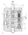
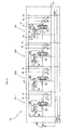
- FIG. 2 and 1 there are shown by way of example, a sectional view of an element E of a load sensing flow sharing directional control valve and the hydraulic circuit of a directional control valve composed of three of such elements E1, E2, E3 respectively, according to a classical configuration, as used by the applicant hereof and as disclosed and claimed in patents EP1628018 and US 7,182,097 .
- these two contacting components operate as a check valve and the piston 5, by mechanically pushing the ball S, causes pressure between the spool 4 and the pressure compensator 3 (pressure in point 2) to be supplied to the LS signal channel C ; through channel C, the pressure in point 2, which is the higher, is transmitted to the pump P and to the other elements and moves apart the pressure compensator 3 and the piston 5 of the elements at lower pressure.
- the piston 5 of the elements at lower pressure abuts on one side;the pressure compensator 3, being subjected to the LS pressure through channel C on one side and to the pressure between the spool 4 and the pressure compensator 3 (pressure in point 2) on the other side 3a, acts as a pressure compensator, thereby imparting to the point 2 of the element at lower pressure the same pressure as at the point 2 of the element that is at higher pressure.
- the elements E1, E2, E3 have the same pressure as the pump P upstream from the spool 4; as a result all the spools 4 are subjected to the same pressure differential, i.e. the one imposed by the pressure compensator 3 on the pump P.
- the flow-rate through the spool 4 is the one required for generating the above pressure differential.
- the flow-rate delivered by the pump P is the one required for such differential to be maintained constant.
- This feature is particularly needed in those operating machines, such as excavators, that are required to perform many simultaneous movements, as it affords proper control of the moving machine even under saturation conditions, which occur quite often.
- an element E4 which will be referred herein as an element having priority, is modified as described below, whereby it does not participate in flow-rate reduction under saturation conditions, while preserving the feature of maintaining a constant flow-rate to the user irrespective of the variation of the load.
- These elements include a proportional control spool 40 and, within the same lapped bore, a local compensator 30 that solves the function of pressure compensator and a piston 50, with a spring M1 of negligible force acting thereon; the piston 50 in turn mechanically operates on the pressure signal selector S1 by keeping it open or closed depending on the pressures on users.
- the spring side M1 of the piston 50 is acted upon by the pressure of the user of its element, as taken between the local compensator 30 and the user itself, the side 30a of the local compensator 30 is acted upon by the pressure taken at point 20, i.e. between the spool 40 and the compensator 30, and the load sensing signal operates between the piston 50 and the local compensator 30.
- the piston 50 presses against the selector S1 of the local compensator 30 and the assembly of the compensator 30 in contact with the piston 50 operate as a one-way valve.
- the selector S1 is kept open by the mechanical action of the piston 50 and connects the pressure signal of point 20, between the spool 40 and the local compensator 30, to the load sensing signal channel C1 ; such signal reaches the pump 100 compensator or alternatively the inlet cover compensator, and arrives between the local compensator 30 and the piston 50 of the elements at lower pressure.
- the piston 50 and the compensator 30 are moved apart from each other; thus, the selector S1 closes and the local compensator 30 fulfills its pressure compensation function.
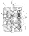
- the element E4 is similar in construction to the above elements E11, E21, E31; the changes to be made to obtain the desired function include:
- the local compensator 9 and the piston / selector 8 are in side-by-side positions within the same lapped bore; the local compensator 9 has a through hole therein, which forms the passage 12 and the piston / selector 8 incorporates a one-way valve 15, which justifies its being referred to as a "piston / selector".
- the spring 14 operates on the side 9a of the local compensator 9 and the plug TT closes the lapped bore that contains these components .
- the piston / selector 8 is subjected to the pressure of the user; if such pressure rises above the pressure at P (excluding the effect of the spring 14), the piston / selector 8 is pushed against the compensator 9, which is in turn pushed to close the passage between P and the user, thus operating as a one-way valve .
- the local compensator 9 is located downstream from the metering recess N of the spool 10 and, within the chamber 19, is no longer subjected to the LS signal pressure but to the pressure of the pump 100; on the opposite side, i.e. within the chamber 13, it is subjected not only to the pressure between the spool 10 and the compensator 9 (pressure at point 11) but also to the spring force 14, which is designed in such a manner as to generate, through the metering recesses N of the spool 10, a pressure differential suitably lower than the general pressure of the present directional control valve V1.
- the pressure at P propagates, through the actuated spool 10, to the chamber 11 and reaches, through the passage 12 within the compensator 9, the chamber 13 with the spring 14 therein.
- the pressure in the chamber 6 is transferred to the channel C1 and from the latter to the pump 100 compensator (or the inlet cover compensator) and further comes between the compensator 30 and the piston 50 of the other elements E11, E21, E31.
- the pump 100 In response to the Load sensing signal pressure in C1, the pump 100 (or the inlet cover compensator) generates a pressure at P which is equal to that in the channel C1, increased by the differential pressure set by the compensator of the pump 100.
- the differential pressure set by the compensator of the pump 100 is assumed to be 14 bar and the action of the spring 14 is assumed to be 5 bar.
- the compensator is subjected to the pressure at P, and on the side of chamber 13 it is subjected to the pressure at P increased by the action of the spring 14; it will thus tend to move to the right, thereby opening the passage between the chamber 11 and the user.
- this component is subjected to pressure at P on the side of chamber 19 and to pressure at 11 plus the action of the spring 14, i.e. 5 bar, on the side of chamber 13.
- the compensator 9 will achieve equilibrium when pressure at 11 will be lower than the pressure at P by 5 bar, i.e. when the flow-rate through the spool 10 will generate a pressure drop of 5 bar.
- the pump 100 senses the load sensing signal pressure and imposes a 14 bar pressure increase at P, whereas the local compensator 9, before the signal to the pump 100 is taken at 6, , suppresses 9 of the 14 bar, thereby reducing the actual pressure differential on the spool 10 to 5 bar.
- the LS signal in C1 moves the compensator 30 and the piston 50 apart, whereas the selector S1 within the compensators 30 closes the connection between points 20 and the LS signal channel C1.
- the compensator 30 will impose on point 20 the same pressure as the LS signal existing in C1, thanks to its own equilibrium.
- the element having priority E4 is not influenced by the LS pressure generated by another element.
- the higher LS signal that reaches the pump 100 (or the inlet cover compensator) generates a higher pressure value at P.
- the pressure at P is non longer equal to the LS signal pressure plus 14 bar, but is decreased to the LS signal pressure plus 10 bar.
- the compensator 9 will continue to open the passage between point 11 and the user (and to reduce the pressure at point 11) until a new equilibrium condition is achieved, i.e. until the pressure at point 11 plus the 5 bar action of the spring 14 corresponds again to the pressure at P.
- the system will behave in the same manner: as pressure decreases at P with respect to the pressure at point 11, the compensator 9 opens the passage between point 11 and the user until a new equilibrium condition is achieved with the same 5 bar pressure drop.
Landscapes
- Engineering & Computer Science (AREA)
- Physics & Mathematics (AREA)
- Fluid Mechanics (AREA)
- Mechanical Engineering (AREA)
- General Engineering & Computer Science (AREA)
- Fluid-Pressure Circuits (AREA)
- Operation Control Of Excavators (AREA)
Claims (3)
- Une soupape de commande directionnelle (V1) avec détection de charge à sections et avec répartition d'un flux, pourvue d'une ou plusieurs sections (E1,... E4), caractérisée en ce qu'au moins une section (E4) de la dite soupape de commande (V1) comprend un compensateur local (9) avec un ressort (14) agissant su un côté (9a) de celui-ci, et un sélecteur/piston (8) ; les dits compensateur local (9) et le sélecteur/piston (8) étant à côté et situés dans le même trou poli; le dit compensateur local (9) étant situé aval d'une cavité de dosage (N) de la bobine (10), ayant un trou qui forme un passage (12) et est soumis à :a. la pression de la pompe (100), au lieu d'une pression d'un signal de détection d'un charge (LS), dans une chambre intermédiaire (19) opposée à une autre chambre (13) qui est agencée par le ressort (14),b. la pression dans le point (11), entre la bobine (10) e le compensateur local (9), plus l'action du ressort (14), dans la chambre (13), le ressort (14) étant prévu pour générer, par les dimensions (N) de la bobine (10), un différentiel de pression inférieur à la pression générale de la soupape de commande directionnelle (V1),
le dit sélecteur/piston (8) comprenant à l'intérieur une soupape unidirectionnelle (15) et étant soumis à :c. la pression d'une pompe entrant dans la chambre intermédiaire (19) à travers d'un trou (16) sur un côté,d. la pression de l'utilisateur, prélevée sur le tube (6), sur le côté opposite, c'est-à-dire sur le côté d'une ultérieure chambre (7),
la dite section (E4) ayant la caractéristique de ne participer pas à une réduction du débit dans des conditions de saturation, c'est-à-dire quand le débit global demandé par les différentes sections (E1,... E4) de la soupape de commande (V1) excède le débit maxi de la pompe, tandis qu'il a encore la caractéristique de maintenir un débit constant pour l'utilisateur, quelle que soi la variation du charge. - Soupape de commande directionnelle (V1) selon la revendication 1, caractérisée en ce que si la pression prélevée sur le tube (6) est supérieure à la pression d'une pompe moins la résistance du ressort (14), le sélecteur/piston (8) est poussé contre le compensateur local (9) qui à fois est poussé pour fermer le passage entre la pompe et l'utilisateur, par l'actionnement d'une soupape unidirectionnelle.
- Soupape de commande directionnelle (V1) selon la revendication 1, caractérisée en ce que le compensateur local (9) de la section ayant priorité (E4) maintient une chute de pression constante à travers de la bobine (10) en manière ainsi de maintenir un débit constant, le compensateur local (9) étant soumis à un côté à la pression de la pompe en (P) et à l'autre côté à la pression dans le point (11) augmentée par l'action du ressort (14), et obtenir un équilibre quand la pression dans le point (11) est inférieure à la pression en (P) moins la valeur du ressort (14), c'est-à-dire quand le débit à travers de la bobine (10) génère une chute de pression constante qui est égale à la valeur constante du ressort (14).
Applications Claiming Priority (1)
| Application Number | Priority Date | Filing Date | Title |
|---|---|---|---|
| PCT/IT2007/000449 WO2009001377A1 (fr) | 2007-06-26 | 2007-06-26 | Soupape de commande directionnelle à détection de charge dont un élément a la priorité dans des conditions de saturation |
Publications (2)
| Publication Number | Publication Date |
|---|---|
| EP2201254A1 EP2201254A1 (fr) | 2010-06-30 |
| EP2201254B1 true EP2201254B1 (fr) | 2011-08-10 |
Family
ID=39079607
Family Applications (1)
| Application Number | Title | Priority Date | Filing Date |
|---|---|---|---|
| EP20070805661 Active EP2201254B1 (fr) | 2007-06-26 | 2007-06-26 | Soupape de commande directionnelle a detection de charge dont un element a la priorite dans des conditions de saturation |
Country Status (5)
| Country | Link |
|---|---|
| US (1) | US8375975B2 (fr) |
| EP (1) | EP2201254B1 (fr) |
| KR (1) | KR101431489B1 (fr) |
| AT (1) | ATE519949T1 (fr) |
| WO (1) | WO2009001377A1 (fr) |
Families Citing this family (8)
| Publication number | Priority date | Publication date | Assignee | Title |
|---|---|---|---|---|
| IT1395462B1 (it) * | 2009-09-03 | 2012-09-21 | Brevini Fluid Power S P A | Valvola di distribuzione |
| WO2011096001A1 (fr) | 2010-02-02 | 2011-08-11 | Bucher Hydraulics S.P.A. | Section hydraulique pour applications de détection de charge et distributeur hydraulique multiple |
| DE102012014359A1 (de) | 2012-07-19 | 2014-01-23 | Hydac Filtertechnik Gmbh | Ventilvorrichtung und Ventilanordnung bestehend aus dahingehenden Ventilvorrichtungen |
| CN103267147B (zh) * | 2013-05-28 | 2015-02-11 | 卢宇 | 一种小流量高压力的负载敏感比例多路阀 |
| JP6656913B2 (ja) * | 2015-12-24 | 2020-03-04 | 株式会社クボタ | 作業機の油圧システム |
| CN108708882B (zh) * | 2018-06-08 | 2020-03-31 | 吴万敏 | 一种用于农机的多路阀 |
| KR102498279B1 (ko) | 2020-12-18 | 2023-02-09 | 충남대학교산학협력단 | 농업용 트랙터의 견인 제어 유압시스템 및 이를 이용한 견인 제어 방법 |
| IT202100009830A1 (it) * | 2021-04-19 | 2022-10-19 | Walvoil Spa | Distributore idraulico con dispositivo di compensazione per valvole direzionali |
Family Cites Families (11)
| Publication number | Priority date | Publication date | Assignee | Title |
|---|---|---|---|---|
| US3703186A (en) * | 1971-08-12 | 1972-11-21 | Gen Motors Corp | Flow divider control valve assembly |
| US3937129A (en) | 1974-10-23 | 1976-02-10 | The Scott & Fetzer Company | Load responsive system with area change flow extender |
| US4206689A (en) * | 1977-08-22 | 1980-06-10 | Caterpillar Tractor Co. | Priority system |
| US4488569A (en) * | 1982-04-23 | 1984-12-18 | Trw Inc. | Apparatus with staged pressure differential for controlling fluid flow |
| US5487403A (en) * | 1987-01-29 | 1996-01-30 | Mollo; James R. | Variable discharge pump with low unload to secondary |
| DE4005967C2 (de) | 1990-02-26 | 1996-05-09 | Rexroth Mannesmann Gmbh | Steueranordnung für mehrere hydraulische Verbraucher |
| DE4237932C2 (de) * | 1992-11-10 | 1997-12-11 | Hydraulik Ring Gmbh | Volumenstromsteuerung für Kraftfahrzeughydraulik, insbesondere für Lenkeinrichtungen von Kraftfahrzeugen |
| US6782697B2 (en) | 2001-12-28 | 2004-08-31 | Caterpillar Inc. | Pressure-compensating valve with load check |
| US6895852B2 (en) * | 2003-05-02 | 2005-05-24 | Husco International, Inc. | Apparatus and method for providing reduced hydraulic flow to a plurality of actuatable devices in a pressure compensated hydraulic system |
| US7182097B2 (en) * | 2004-08-17 | 2007-02-27 | Walvoil S.P.A. | Anti-saturation directional control valve composed of two or more sections with pressure selector compensators |
| ITPR20060036A1 (it) * | 2006-04-12 | 2007-10-13 | Walvoil Spa | Compensatore di pressione ad aree differenziali pilotato e suo sistema di pilotaggio. |
-
2007
- 2007-06-26 EP EP20070805661 patent/EP2201254B1/fr active Active
- 2007-06-26 US US12/666,754 patent/US8375975B2/en active Active
- 2007-06-26 KR KR1020107001321A patent/KR101431489B1/ko not_active Expired - Fee Related
- 2007-06-26 AT AT07805661T patent/ATE519949T1/de not_active IP Right Cessation
- 2007-06-26 WO PCT/IT2007/000449 patent/WO2009001377A1/fr not_active Ceased
Also Published As
| Publication number | Publication date |
|---|---|
| US20100176324A1 (en) | 2010-07-15 |
| EP2201254A1 (fr) | 2010-06-30 |
| KR101431489B1 (ko) | 2014-08-20 |
| WO2009001377A1 (fr) | 2008-12-31 |
| US8375975B2 (en) | 2013-02-19 |
| ATE519949T1 (de) | 2011-08-15 |
| KR20100023038A (ko) | 2010-03-03 |
Similar Documents
| Publication | Publication Date | Title |
|---|---|---|
| EP2201254B1 (fr) | Soupape de commande directionnelle a detection de charge dont un element a la priorite dans des conditions de saturation | |
| EP0911529B1 (fr) | Système de soupapes de réglage hydraulique avec compensateur de pression sans valve de sélection | |
| US9874884B2 (en) | Valve block having a valve assembly | |
| JP4739529B2 (ja) | 少なくとも2つの液圧式の消費器用の制御ユニットおよび該制御ユニット用の差圧弁 | |
| EP2078868A3 (fr) | Système de soupape de commande hydraulique doté d'une système de détection de charge | |
| CA2241248A1 (fr) | Systeme de valves de compensation de pression pour commande hydraulique | |
| CN109707688B (zh) | 一种具有前置压力补偿器的流量抗饱负载敏感多路阀 | |
| EP1008754B1 (fr) | Systèmes de pompe à déplacement positif | |
| US8430016B2 (en) | Control valve assembly with a workport pressure regulating device | |
| US4275643A (en) | Hydraulic control systems | |
| DE602005002097D1 (de) | Mehrwegeventilanordnung mit eingebautem Wechselventil zur Lastdruckmeldung versehenen Druckwaagen, mit Unterversorgungsvermeidungsfunktion | |
| US12123502B2 (en) | Inlet section for use in a hydraulic distributor | |
| CN104653530A (zh) | 液压的控制系统 | |
| CN106715924A (zh) | 感载阀装置 | |
| JP2010534816A (ja) | 少なくとも2つのハイドロリック式の消費器を制御するための制御装置および方法 | |
| JP2007032782A (ja) | 油圧駆動装置 | |
| WO2016072322A1 (fr) | Dispositif de valve sensible à la charge | |
| JP4960646B2 (ja) | ロードセンシング式油圧制御装置 | |
| USRE29671E (en) | Demand compensated hydraulic system with flow sensitive device | |
| JP2647094B2 (ja) | リリーフ弁 | |
| JP3240286B2 (ja) | 油圧システム | |
| JPH01312201A (ja) | 油圧流量制御装置 | |
| JP4791823B2 (ja) | ロードセンシング方式の油圧制御装置に用いられる油圧制御弁 | |
| GB2533034A (en) | Systems and methods for flow summation in a hydraulic system with open center control valves | |
| JP2007270982A (ja) | 建設機械の油圧制御装置 |
Legal Events
| Date | Code | Title | Description |
|---|---|---|---|
| PUAI | Public reference made under article 153(3) epc to a published international application that has entered the european phase |
Free format text: ORIGINAL CODE: 0009012 |
|
| 17P | Request for examination filed |
Effective date: 20100208 |
|
| AK | Designated contracting states |
Kind code of ref document: A1 Designated state(s): AT BE BG CH CY CZ DE DK EE ES FI FR GB GR HU IE IS IT LI LT LU LV MC MT NL PL PT RO SE SI SK TR |
|
| AX | Request for extension of the european patent |
Extension state: AL BA HR MK RS |
|
| DAX | Request for extension of the european patent (deleted) | ||
| GRAP | Despatch of communication of intention to grant a patent |
Free format text: ORIGINAL CODE: EPIDOSNIGR1 |
|
| GRAS | Grant fee paid |
Free format text: ORIGINAL CODE: EPIDOSNIGR3 |
|
| GRAA | (expected) grant |
Free format text: ORIGINAL CODE: 0009210 |
|
| AK | Designated contracting states |
Kind code of ref document: B1 Designated state(s): AT BE BG CH CY CZ DE DK EE ES FI FR GB GR HU IE IS IT LI LT LU LV MC MT NL PL PT RO SE SI SK TR |
|
| REG | Reference to a national code |
Ref country code: GB Ref legal event code: FG4D |
|
| REG | Reference to a national code |
Ref country code: CH Ref legal event code: EP |
|
| REG | Reference to a national code |
Ref country code: IE Ref legal event code: FG4D |
|
| REG | Reference to a national code |
Ref country code: DE Ref legal event code: R096 Ref document number: 602007016475 Country of ref document: DE Effective date: 20111013 |
|
| REG | Reference to a national code |
Ref country code: NL Ref legal event code: VDEP Effective date: 20110810 |
|
| LTIE | Lt: invalidation of european patent or patent extension |
Effective date: 20110810 |
|
| PG25 | Lapsed in a contracting state [announced via postgrant information from national office to epo] |
Ref country code: FI Free format text: LAPSE BECAUSE OF FAILURE TO SUBMIT A TRANSLATION OF THE DESCRIPTION OR TO PAY THE FEE WITHIN THE PRESCRIBED TIME-LIMIT Effective date: 20110810 Ref country code: IS Free format text: LAPSE BECAUSE OF FAILURE TO SUBMIT A TRANSLATION OF THE DESCRIPTION OR TO PAY THE FEE WITHIN THE PRESCRIBED TIME-LIMIT Effective date: 20111210 Ref country code: NL Free format text: LAPSE BECAUSE OF FAILURE TO SUBMIT A TRANSLATION OF THE DESCRIPTION OR TO PAY THE FEE WITHIN THE PRESCRIBED TIME-LIMIT Effective date: 20110810 Ref country code: LT Free format text: LAPSE BECAUSE OF FAILURE TO SUBMIT A TRANSLATION OF THE DESCRIPTION OR TO PAY THE FEE WITHIN THE PRESCRIBED TIME-LIMIT Effective date: 20110810 Ref country code: SE Free format text: LAPSE BECAUSE OF FAILURE TO SUBMIT A TRANSLATION OF THE DESCRIPTION OR TO PAY THE FEE WITHIN THE PRESCRIBED TIME-LIMIT Effective date: 20110810 Ref country code: PT Free format text: LAPSE BECAUSE OF FAILURE TO SUBMIT A TRANSLATION OF THE DESCRIPTION OR TO PAY THE FEE WITHIN THE PRESCRIBED TIME-LIMIT Effective date: 20111212 |
|
| REG | Reference to a national code |
Ref country code: AT Ref legal event code: MK05 Ref document number: 519949 Country of ref document: AT Kind code of ref document: T Effective date: 20110810 |
|
| PG25 | Lapsed in a contracting state [announced via postgrant information from national office to epo] |
Ref country code: GR Free format text: LAPSE BECAUSE OF FAILURE TO SUBMIT A TRANSLATION OF THE DESCRIPTION OR TO PAY THE FEE WITHIN THE PRESCRIBED TIME-LIMIT Effective date: 20111111 Ref country code: LV Free format text: LAPSE BECAUSE OF FAILURE TO SUBMIT A TRANSLATION OF THE DESCRIPTION OR TO PAY THE FEE WITHIN THE PRESCRIBED TIME-LIMIT Effective date: 20110810 Ref country code: SI Free format text: LAPSE BECAUSE OF FAILURE TO SUBMIT A TRANSLATION OF THE DESCRIPTION OR TO PAY THE FEE WITHIN THE PRESCRIBED TIME-LIMIT Effective date: 20110810 Ref country code: AT Free format text: LAPSE BECAUSE OF FAILURE TO SUBMIT A TRANSLATION OF THE DESCRIPTION OR TO PAY THE FEE WITHIN THE PRESCRIBED TIME-LIMIT Effective date: 20110810 Ref country code: PL Free format text: LAPSE BECAUSE OF FAILURE TO SUBMIT A TRANSLATION OF THE DESCRIPTION OR TO PAY THE FEE WITHIN THE PRESCRIBED TIME-LIMIT Effective date: 20110810 Ref country code: CY Free format text: LAPSE BECAUSE OF FAILURE TO SUBMIT A TRANSLATION OF THE DESCRIPTION OR TO PAY THE FEE WITHIN THE PRESCRIBED TIME-LIMIT Effective date: 20110810 |
|
| PG25 | Lapsed in a contracting state [announced via postgrant information from national office to epo] |
Ref country code: BE Free format text: LAPSE BECAUSE OF FAILURE TO SUBMIT A TRANSLATION OF THE DESCRIPTION OR TO PAY THE FEE WITHIN THE PRESCRIBED TIME-LIMIT Effective date: 20110810 |
|
| PG25 | Lapsed in a contracting state [announced via postgrant information from national office to epo] |
Ref country code: CZ Free format text: LAPSE BECAUSE OF FAILURE TO SUBMIT A TRANSLATION OF THE DESCRIPTION OR TO PAY THE FEE WITHIN THE PRESCRIBED TIME-LIMIT Effective date: 20110810 Ref country code: SK Free format text: LAPSE BECAUSE OF FAILURE TO SUBMIT A TRANSLATION OF THE DESCRIPTION OR TO PAY THE FEE WITHIN THE PRESCRIBED TIME-LIMIT Effective date: 20110810 |
|
| PG25 | Lapsed in a contracting state [announced via postgrant information from national office to epo] |
Ref country code: RO Free format text: LAPSE BECAUSE OF FAILURE TO SUBMIT A TRANSLATION OF THE DESCRIPTION OR TO PAY THE FEE WITHIN THE PRESCRIBED TIME-LIMIT Effective date: 20110810 Ref country code: EE Free format text: LAPSE BECAUSE OF FAILURE TO SUBMIT A TRANSLATION OF THE DESCRIPTION OR TO PAY THE FEE WITHIN THE PRESCRIBED TIME-LIMIT Effective date: 20110810 |
|
| PLBE | No opposition filed within time limit |
Free format text: ORIGINAL CODE: 0009261 |
|
| STAA | Information on the status of an ep patent application or granted ep patent |
Free format text: STATUS: NO OPPOSITION FILED WITHIN TIME LIMIT |
|
| PG25 | Lapsed in a contracting state [announced via postgrant information from national office to epo] |
Ref country code: DK Free format text: LAPSE BECAUSE OF FAILURE TO SUBMIT A TRANSLATION OF THE DESCRIPTION OR TO PAY THE FEE WITHIN THE PRESCRIBED TIME-LIMIT Effective date: 20110810 |
|
| 26N | No opposition filed |
Effective date: 20120511 |
|
| REG | Reference to a national code |
Ref country code: DE Ref legal event code: R097 Ref document number: 602007016475 Country of ref document: DE Effective date: 20120511 |
|
| PG25 | Lapsed in a contracting state [announced via postgrant information from national office to epo] |
Ref country code: MC Free format text: LAPSE BECAUSE OF NON-PAYMENT OF DUE FEES Effective date: 20120630 |
|
| REG | Reference to a national code |
Ref country code: CH Ref legal event code: PL |
|
| REG | Reference to a national code |
Ref country code: CH Ref legal event code: PL |
|
| GBPC | Gb: european patent ceased through non-payment of renewal fee |
Effective date: 20120626 |
|
| REG | Reference to a national code |
Ref country code: IE Ref legal event code: MM4A |
|
| PG25 | Lapsed in a contracting state [announced via postgrant information from national office to epo] |
Ref country code: LI Free format text: LAPSE BECAUSE OF NON-PAYMENT OF DUE FEES Effective date: 20120630 Ref country code: IE Free format text: LAPSE BECAUSE OF NON-PAYMENT OF DUE FEES Effective date: 20120626 Ref country code: ES Free format text: LAPSE BECAUSE OF FAILURE TO SUBMIT A TRANSLATION OF THE DESCRIPTION OR TO PAY THE FEE WITHIN THE PRESCRIBED TIME-LIMIT Effective date: 20111121 Ref country code: GB Free format text: LAPSE BECAUSE OF NON-PAYMENT OF DUE FEES Effective date: 20120626 Ref country code: CH Free format text: LAPSE BECAUSE OF NON-PAYMENT OF DUE FEES Effective date: 20120630 |
|
| PG25 | Lapsed in a contracting state [announced via postgrant information from national office to epo] |
Ref country code: BG Free format text: LAPSE BECAUSE OF FAILURE TO SUBMIT A TRANSLATION OF THE DESCRIPTION OR TO PAY THE FEE WITHIN THE PRESCRIBED TIME-LIMIT Effective date: 20111110 |
|
| PG25 | Lapsed in a contracting state [announced via postgrant information from national office to epo] |
Ref country code: MT Free format text: LAPSE BECAUSE OF FAILURE TO SUBMIT A TRANSLATION OF THE DESCRIPTION OR TO PAY THE FEE WITHIN THE PRESCRIBED TIME-LIMIT Effective date: 20110810 |
|
| PG25 | Lapsed in a contracting state [announced via postgrant information from national office to epo] |
Ref country code: LU Free format text: LAPSE BECAUSE OF NON-PAYMENT OF DUE FEES Effective date: 20120626 |
|
| PG25 | Lapsed in a contracting state [announced via postgrant information from national office to epo] |
Ref country code: HU Free format text: LAPSE BECAUSE OF FAILURE TO SUBMIT A TRANSLATION OF THE DESCRIPTION OR TO PAY THE FEE WITHIN THE PRESCRIBED TIME-LIMIT Effective date: 20070626 |
|
| REG | Reference to a national code |
Ref country code: FR Ref legal event code: PLFP Year of fee payment: 10 |
|
| REG | Reference to a national code |
Ref country code: FR Ref legal event code: PLFP Year of fee payment: 11 |
|
| REG | Reference to a national code |
Ref country code: FR Ref legal event code: PLFP Year of fee payment: 12 |
|
| PGFP | Annual fee paid to national office [announced via postgrant information from national office to epo] |
Ref country code: FR Payment date: 20230620 Year of fee payment: 17 Ref country code: DE Payment date: 20230620 Year of fee payment: 17 |
|
| P01 | Opt-out of the competence of the unified patent court (upc) registered |
Effective date: 20230622 |
|
| PGFP | Annual fee paid to national office [announced via postgrant information from national office to epo] |
Ref country code: TR Payment date: 20230620 Year of fee payment: 17 |
|
| PGFP | Annual fee paid to national office [announced via postgrant information from national office to epo] |
Ref country code: IT Payment date: 20230630 Year of fee payment: 17 |
|
| REG | Reference to a national code |
Ref country code: DE Ref legal event code: R119 Ref document number: 602007016475 Country of ref document: DE |
|
| PG25 | Lapsed in a contracting state [announced via postgrant information from national office to epo] |
Ref country code: DE Free format text: LAPSE BECAUSE OF NON-PAYMENT OF DUE FEES Effective date: 20250101 |
|
| PG25 | Lapsed in a contracting state [announced via postgrant information from national office to epo] |
Ref country code: FR Free format text: LAPSE BECAUSE OF NON-PAYMENT OF DUE FEES Effective date: 20240630 |
|
| PG25 | Lapsed in a contracting state [announced via postgrant information from national office to epo] |
Ref country code: IT Free format text: LAPSE BECAUSE OF NON-PAYMENT OF DUE FEES Effective date: 20240626 |