EP2201311B1 - Système et procédé de refroidissement de structures présentant à la fois un état actif et un état inactif - Google Patents
Système et procédé de refroidissement de structures présentant à la fois un état actif et un état inactif Download PDFInfo
- Publication number
- EP2201311B1 EP2201311B1 EP08798833.3A EP08798833A EP2201311B1 EP 2201311 B1 EP2201311 B1 EP 2201311B1 EP 08798833 A EP08798833 A EP 08798833A EP 2201311 B1 EP2201311 B1 EP 2201311B1
- Authority
- EP
- European Patent Office
- Prior art keywords
- heat
- fluid coolant
- generating structure
- temperature
- inactive
- Prior art date
- Legal status (The legal status is an assumption and is not a legal conclusion. Google has not performed a legal analysis and makes no representation as to the accuracy of the status listed.)
- Active
Links
Images

Classifications
-
- F—MECHANICAL ENGINEERING; LIGHTING; HEATING; WEAPONS; BLASTING
- F25—REFRIGERATION OR COOLING; COMBINED HEATING AND REFRIGERATION SYSTEMS; HEAT PUMP SYSTEMS; MANUFACTURE OR STORAGE OF ICE; LIQUEFACTION SOLIDIFICATION OF GASES
- F25B—REFRIGERATION MACHINES, PLANTS OR SYSTEMS; COMBINED HEATING AND REFRIGERATION SYSTEMS; HEAT PUMP SYSTEMS
- F25B23/00—Machines, plants or systems, with a single mode of operation not covered by groups F25B1/00 - F25B21/00, e.g. using selective radiation effect
- F25B23/006—Machines, plants or systems, with a single mode of operation not covered by groups F25B1/00 - F25B21/00, e.g. using selective radiation effect boiling cooling systems
-
- F—MECHANICAL ENGINEERING; LIGHTING; HEATING; WEAPONS; BLASTING
- F28—HEAT EXCHANGE IN GENERAL
- F28D—HEAT-EXCHANGE APPARATUS, NOT PROVIDED FOR IN ANOTHER SUBCLASS, IN WHICH THE HEAT-EXCHANGE MEDIA DO NOT COME INTO DIRECT CONTACT
- F28D15/00—Heat-exchange apparatus with the intermediate heat-transfer medium in closed tubes passing into or through the conduit walls ; Heat-exchange apparatus employing intermediate heat-transfer medium or bodies
-
- H—ELECTRICITY
- H01—ELECTRIC ELEMENTS
- H01Q—ANTENNAS, i.e. RADIO AERIALS
- H01Q1/00—Details of, or arrangements associated with, antennas
- H01Q1/02—Arrangements for de-icing; Arrangements for drying-out ; Arrangements for cooling; Arrangements for preventing corrosion
-
- H—ELECTRICITY
- H05—ELECTRIC TECHNIQUES NOT OTHERWISE PROVIDED FOR
- H05K—PRINTED CIRCUITS; CASINGS OR CONSTRUCTIONAL DETAILS OF ELECTRIC APPARATUS; MANUFACTURE OF ASSEMBLAGES OF ELECTRICAL COMPONENTS
- H05K7/00—Constructional details common to different types of electric apparatus
- H05K7/20—Modifications to facilitate cooling, ventilating, or heating
- H05K7/20218—Modifications to facilitate cooling, ventilating, or heating using a liquid coolant without phase change in electronic enclosures
- H05K7/20281—Thermal management, e.g. liquid flow control
Definitions
- cooling systems may be used to cool commercial and military applications. Although these cooling systems may minimize a need for conditioned air, they may be limited by the amount of structures being cooled and the current state of each structure (i.e. active, inactive, standby).
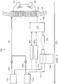
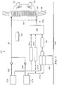
- a fluid coolant flows through each of the structure heat exchangers 23, 24.
- the fluid coolant absorbs heat from the structure 12.
- the structure heat exchangers 23, 24 may be lined with pin fins or other similar devices which, among other things, increase surface contact between the fluid coolant and walls of the structure heat exchangers 23, 24.
- the fluid coolant may be forced or sprayed into the structure heat exchangers 23, 24 to ensure fluid contact between the fluid coolant and the walls of the structure heat exchangers 23, 24.
- the fluid coolant may remain in a liquid phase after absorption of heat from the structure 12.
- the absorption of heat from the structure 12 may cause at least a portion of the fluid coolant to vaporize.
Landscapes
- Engineering & Computer Science (AREA)
- Physics & Mathematics (AREA)
- Thermal Sciences (AREA)
- Mechanical Engineering (AREA)
- General Engineering & Computer Science (AREA)
- Microelectronics & Electronic Packaging (AREA)
- Cooling Or The Like Of Electrical Apparatus (AREA)
Claims (13)
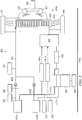
- Système (400) de refroidissement de structures génératrices de chaleur, comprenant :une structure génératrice de chaleur active (412a) ;une structure génératrice de chaleur inactive (412b) ;une boucle de refroidissement (419a) comportant une pompe (446) qui dirige un premier flux d'un fluide de refroidissement vers la structure génératrice de chaleur active (412a) et un deuxième flux du fluide de refroidissement vers la structure génératrice de chaleur inactive (412b), le fluide de refroidissement recevant l'énergie thermique provenant de la structure génératrice de chaleur active (412a), le fluide de refroidissement transférant l'énergie thermique à la structure génératrice de chaleur inactive (412b) lorsqu'une température du fluide de refroidissement est supérieure à une température ambiante d'un environnement entourant les structures génératrices de chaleur active et inactive (412a, 412b), moyennant quoi la structure génératrice de chaleur inactive (412b) peut être empêchée de descendre en-dessous d'une température de fonctionnement optimale, la structure génératrice de chaleur active (412a) étant actionnable pour passer à l'état inactif, et la structure génératrice de chaleur inactive (412b) étant actionnable pour passer à l'état actif ;un premier capteur (484) actionnable pour mesurer une température du premier flux du fluide de refroidissement au niveau d'une conduite de sortie (428a) de la structure génératrice de chaleur active (412a) et un deuxième capteur (485) actionnable pour mesurer une température du deuxième flux du fluide de refroidissement au niveau d'une conduite de sortie (428b) de la structure génératrice de chaleur inactive (412b) ; etun échangeur thermique (441) communiquant thermiquement avec les structures génératrices de chaleur active et inactive (412a, 412b), l'échangeur thermique (441) étant actionnable pour recevoir le fluide de refroidissement à une première température et pour distribuer le fluide de refroidissement hors de l'échangeur thermique (441) à une deuxième température ;la boucle de refroidissement (419a) dirigeant en outre un troisième flux du fluide de refroidissement vers l'échangeur thermique (441), le troisième flux du fluide de refroidissement étant une combinaison des premier et deuxième flux du fluide de refroidissement ; etl'échangeur thermique (441) présentant un port d'entrée actionnable pour recevoir le fluide de refroidissement à la première température, et l'échangeur thermique (441) présentant en outre un port de sortie actionnable pour distribuer le fluide de refroidissement hors de l'échangeur thermique (441) à la deuxième température.
- Système (400) selon la revendication 1, comprenant en outre :une deuxième structure génératrice de chaleur active ;une deuxième structure génératrice de chaleur inactive ;une seconde boucle de refroidissement comportant une seconde pompe qui dirige un premier flux d'un second fluide de refroidissement vers la deuxième structure génératrice de chaleur active et un deuxième flux du second fluide de refroidissement vers la deuxième structure génératrice de chaleur inactive, le second fluide de refroidissement recevant l'énergie thermique provenant de la deuxième structure génératrice de chaleur active, le second fluide de refroidissement transférant l'énergie thermique à la deuxième structure génératrice de chaleur inactive lorsqu'une température du second fluide de refroidissement est supérieure à une température ambiante d'un environnement entourant les deuxièmes structures génératrices de chaleur active et inactive, moyennant quoi la deuxième structure génératrice de chaleur inactive peut être empêchée de descendre en-dessous d'une température de fonctionnement optimale, la deuxième structure génératrice de chaleur active étant actionnable pour passer à l'état inactif, et la deuxième structure génératrice de chaleur inactive étant actionnable pour passer à l'état actif ;un troisième capteur étant actionnable pour mesurer une température du premier flux du second fluide de refroidissement au niveau d'une conduite de sortie de la deuxième structure génératrice de chaleur active et un quatrième capteur actionnable pour mesurer une température du deuxième flux du second fluide de refroidissement au niveau d'une conduite de sortie de la deuxième structure génératrice de chaleur inactive ; etun second échangeur thermique communiquant thermiquement avec les deuxièmes structures génératrices de chaleur active et inactive, le second échangeur thermique étant actionnable pour recevoir le second fluide de refroidissement à une troisième température et de distribuer le second fluide de refroidissement hors du second échangeur thermique à une quatrième température ;la seconde boucle de refroidissement dirigeant en outre un troisième flux du second fluide de refroidissement vers le second échangeur thermique, le troisième flux du second fluide de refroidissement étant une combinaison des premier et deuxième flux du second fluide de refroidissement ; etle second échangeur thermique présentant un port d'entrée étant actionnable pour recevoir le second fluide de refroidissement à la troisième température, et le second échangeur thermique présentant en outre un port de sortie actionnable pour distribuer le second fluide de refroidissement hors du second échangeur thermique à la quatrième température.
- Système (400) selon la revendication 1, dans lequel l'échangeur thermique est soit un échangeur thermique liquide-air, soit un échangeur thermique liquide-liquide.
- Système (400) selon la revendication 1, comprenant en outre un capteur (487, 489, 490) actionnable pour mesurer l'une d'une puissance de pompe, d'une puissance de ventilateur et d'une chute de pression dans le système (400).
- Système (400) selon la revendication 2, dans lequel la structure génératrice de chaleur active (412a) est orientée dans une première direction, la structure génératrice de chaleur inactive (412b) est orientée dans une deuxième direction, la deuxième structure génératrice de chaleur active est orientée dans une troisième direction, et la deuxième structure génératrice de chaleur inactive est orientée dans une quatrième direction, la première direction étant opposée à la troisième direction, et la deuxième direction étant opposée à la quatrième direction.
- Système (400) selon la revendication 2, dans lequel les premier et deuxième flux du fluide de refroidissement sont sensiblement égaux, et dans lequel les premier et deuxième flux du second fluide de refroidissement sont sensiblement égaux.
- Système (400) selon la revendication 2, dans lequel les premier et deuxième flux du fluide de refroidissement présentent des températures sensiblement égales, et dans lequel les premier et deuxième flux du second fluide de refroidissement présentent des températures sensiblement égales.
- Procédé de refroidissement de structures génératrices de chaleur, comprenant :la direction d'un premier flux d'un fluide de refroidissement depuis une pompe (446) vers une première structure génératrice de chaleur (412a) ;la direction d'un deuxième flux du fluide de refroidissement depuis la pompe (446) vers une deuxième structure génératrice de chaleur (412b), l'une de la première structure génératrice de chaleur (412a) et de la deuxième structure génératrice de chaleur (412b) étant à l'état actif, et l'autre de la première structure génératrice de chaleur (412a) et de la deuxième structure génératrice de chaleur (412b) étant à l'état inactif ;la direction d'un troisième flux du fluide de refroidissement vers un échangeur thermique (441), le troisième flux du fluide de refroidissement étant une combinaison des premier et deuxième flux du fluide de refroidissement, le fluide de refroidissement transférant l'énergie thermique à la première structure génératrice de chaleur (412a) ou à la deuxième structure génératrice de chaleur (412b) qui est à l'état inactif lorsqu'une température du fluide de refroidissement est supérieure à une température ambiante d'un environnement entourant les première et deuxième structures génératrices de chaleur (412a, 412b), moyennant quoi la première structure génératrice de chaleur (412a) ou la deuxième structure génératrice de chaleur (412b) qui est à l'état inactif peut être empêchée de descendre en-dessous d'une température de fonctionnement optimale ;la mesure d'une température du premier flux du fluide de refroidissement au niveau d'une conduite de sortie (428a) de la première structure génératrice de chaleur (412a) à l'aide d'un premier capteur (484) et la mesure d'une température du deuxième flux du fluide de refroidissement au niveau d'une conduite de sortie (428b) de la deuxième structure génératrice de chaleur (412b) à l'aide d'un deuxième capteur (485) ;la réception, au niveau de l'échangeur thermique (441), du fluide de refroidissement à une première température, l'échangeur thermique (441) communiquant thermiquement avec les première et deuxième structures génératrices de chaleur (412a, 412b) ; etla distribution, depuis le premier échangeur thermique (441), du fluide de refroidissement à une deuxième température.
- Procédé selon la revendication 8, comprenant en outre :la direction d'un premier flux d'un second fluide de refroidissement depuis une seconde pompe vers une troisième structure génératrice de chaleur ;la direction d'un deuxième flux du second fluide de refroidissement depuis la seconde pompe vers une quatrième structure génératrice de chaleur, l'une de la troisième structure génératrice de chaleur et de la quatrième structure génératrice de chaleur étant à l'état actif, et l'autre de la troisième structure génératrice de chaleur et de la quatrième structure génératrice de chaleur étant à l'état inactif ;la direction d'un troisième flux du second fluide de refroidissement vers un second échangeur thermique, le troisième flux du second fluide de refroidissement étant une combinaison des premier et deuxième flux du second fluide de refroidissement, le second fluide de refroidissement transférant l'énergie thermique à la troisième structure génératrice de chaleur ou à la quatrième structure génératrice de chaleur qui est à l'état inactif lorsqu'une température du second fluide de refroidissement est supérieure à une température ambiante d'un environnement entourant les troisième et quatrième structures génératrices de chaleur, moyennant quoi la troisième structure génératrice de chaleur ou la quatrième structure génératrice de chaleur qui est à l'état inactif peut être empêchée de descendre en-dessous d'une température de fonctionnement optimale ;la mesure d'une température du premier flux du second fluide de refroidissement au niveau d'une conduite de sortie de la troisième structure génératrice de chaleur à l'aide d'un troisième capteur et la mesure d'une température du deuxième flux du second fluide de refroidissement au niveau d'une conduite de sortie de la quatrième structure génératrice de chaleur à l'aide d'un quatrième capteur ;la réception, au niveau du second échangeur thermique, du second fluide de refroidissement à une troisième température, le second échangeur thermique communiquant thermiquement avec les troisième et quatrième structures génératrices de chaleur ; etla distribution, depuis le second échangeur thermique, du second fluide de refroidissement à une quatrième température.
- Procédé selon la revendication 9, dans lequel la première structure génératrice de chaleur (412a) est orientée dans une première direction, la deuxième structure génératrice de chaleur (412b) est orientée dans une deuxième direction, la troisième structure génératrice de chaleur est orientée dans une troisième direction, et la quatrième structure génératrice de chaleur est orientée dans une quatrième direction, la première direction étant opposée à la troisième direction, et la deuxième direction étant opposée à la quatrième direction.
- Procédé selon la revendication 9, dans lequel les premier et deuxième flux du fluide de refroidissement sont sensiblement égaux, et dans lequel les premier et deuxième flux du second fluide de refroidissement sont sensiblement égaux.
- Procédé selon la revendication 9, dans lequel les premier et deuxième flux du fluide de refroidissement présentent des températures sensiblement égales, et dans lequel les premier et deuxième flux du second fluide de refroidissement présentent des températures sensiblement égales.
- Procédé selon la revendication 9, comprenant en outre :
la mesure d'une ou plusieurs pressions du système de refroidissement (400).
Applications Claiming Priority (2)
| Application Number | Priority Date | Filing Date | Title |
|---|---|---|---|
| US11/924,335 US9644869B2 (en) | 2007-10-25 | 2007-10-25 | System and method for cooling structures having both an active state and an inactive state |
| PCT/US2008/074542 WO2009055142A1 (fr) | 2007-10-25 | 2008-08-28 | Système et procédé de refroidissement de structures présentant à la fois un état actif et un état inactif |
Publications (2)
| Publication Number | Publication Date |
|---|---|
| EP2201311A1 EP2201311A1 (fr) | 2010-06-30 |
| EP2201311B1 true EP2201311B1 (fr) | 2019-02-27 |
Family
ID=40032886
Family Applications (1)
| Application Number | Title | Priority Date | Filing Date |
|---|---|---|---|
| EP08798833.3A Active EP2201311B1 (fr) | 2007-10-25 | 2008-08-28 | Système et procédé de refroidissement de structures présentant à la fois un état actif et un état inactif |
Country Status (3)
| Country | Link |
|---|---|
| US (1) | US9644869B2 (fr) |
| EP (1) | EP2201311B1 (fr) |
| WO (1) | WO2009055142A1 (fr) |
Families Citing this family (5)
| Publication number | Priority date | Publication date | Assignee | Title |
|---|---|---|---|---|
| ATE554361T1 (de) * | 2009-04-28 | 2012-05-15 | Abb Research Ltd | Wärmerohr mit gewundenem rohr |
| EP2246654B1 (fr) * | 2009-04-29 | 2013-12-11 | ABB Research Ltd. | Échangeur thermique à thermosiphon à rangs multiples |
| CN108281401A (zh) * | 2017-01-05 | 2018-07-13 | 研能科技股份有限公司 | 三维芯片集成电路冷却系统 |
| US10273867B2 (en) * | 2017-02-02 | 2019-04-30 | GM Global Technology Operations LLC | Prognostic system and method for an electric coolant pump |
| CN113865137B (zh) * | 2021-09-08 | 2022-12-09 | 美的集团武汉暖通设备有限公司 | 一种空气源热泵系统及空气源热泵的控制方法 |
Citations (1)
| Publication number | Priority date | Publication date | Assignee | Title |
|---|---|---|---|---|
| US20020101716A1 (en) * | 2000-12-19 | 2002-08-01 | Tsuyoshi Nakagawa | Liquid cooling system for notebook computer |
Family Cites Families (30)
| Publication number | Priority date | Publication date | Assignee | Title |
|---|---|---|---|---|
| US1004212A (en) * | 1911-06-29 | 1911-09-26 | Samuel Charles Smith | Rotary pump. |
| US2466440A (en) * | 1948-07-29 | 1949-04-05 | Kiekhaefer Elmer Carl | Impeller for rotary pumps |
| US2821271A (en) * | 1954-05-03 | 1958-01-28 | Roy S Sanford | Liquid cooled brake with copper friction surfaces |
| US3014429A (en) * | 1959-01-15 | 1961-12-26 | Jabsco Pump Co | Tandem pump |
| US3394655A (en) * | 1966-09-19 | 1968-07-30 | Richard J. Brown | Combined centrifugal and jet type fluid pump |
| EP0091228A1 (fr) * | 1982-04-07 | 1983-10-12 | Hammond Engineering Limited | Carter de ventilateur, ventilateur, et dispositif pourvu d'un tel ventilateur |
| JPS6293426A (ja) * | 1985-10-21 | 1987-04-28 | Honda Motor Co Ltd | V型多気筒エンジン用冷却水ポンプ |
| FR2602035B1 (fr) | 1986-04-23 | 1990-05-25 | Michel Bosteels | Procede et installation de transfert de chaleur entre un fluide et un organe a refroidir ou rechauffer, par mise en depression du fluide par rapport a la pression atmospherique |
| US4766928A (en) * | 1986-10-27 | 1988-08-30 | Packaged Systems, Inc. | Constant flow rate control valve |
| US5174330A (en) * | 1991-12-05 | 1992-12-29 | Flow Design, Inc. | Constant flow rate control valve with low pressure drop start |
| US5398519A (en) * | 1992-07-13 | 1995-03-21 | Texas Instruments Incorporated | Thermal control system |
| US5459474A (en) * | 1994-03-22 | 1995-10-17 | Martin Marietta Corporation | Active array antenna radar structure |
| WO1996031694A1 (fr) * | 1995-04-05 | 1996-10-10 | Schatz Thermo System Gmbh | Procede et circuit permettant de faire fonctionner des accumulateurs de chaleur, notamment de chaleur sensible |
| DE19606584C2 (de) * | 1995-04-19 | 1997-07-31 | Porsche Ag | Verfahren zur Zylinderabschaltung einer Brennkraftmaschine |
| US5832991A (en) * | 1995-12-29 | 1998-11-10 | Cesaroni; Joseph Anthony | Tube and shell heat exchanger with baffle |
| US5852563A (en) * | 1996-04-10 | 1998-12-22 | Raytheon Ti Systems, Inc. | Intelligent coolant flow control system |
| US6205803B1 (en) | 1996-04-26 | 2001-03-27 | Mainstream Engineering Corporation | Compact avionics-pod-cooling unit thermal control method and apparatus |
| GB2387276B (en) | 1998-10-09 | 2003-11-26 | Ericsson Inc | Controlling electronics cabinet temperatures |
| US6094925A (en) | 1999-01-29 | 2000-08-01 | Delaware Capital Formation, Inc. | Crossover warm liquid defrost refrigeration system |
| DE10038161A1 (de) | 2000-08-04 | 2002-02-21 | Infineon Technologies Ag | Kühlvorrichtung für elektronische Bauteile und Verfahren zur Herstellung der Kühlvorrichtung |
| US7017651B1 (en) * | 2000-09-13 | 2006-03-28 | Raytheon Company | Method and apparatus for temperature gradient control in an electronic system |
| IT1319610B1 (it) | 2000-12-22 | 2003-10-20 | Siemens Inf & Comm Networks | Procedimento e apparecchiatura per il condizionamento termico diarmadi contenenti apparecchiature elettroniche |
| US6345512B1 (en) * | 2001-06-15 | 2002-02-12 | Marconi Communications, Inc. | Power efficient, compact DC cooling system |
| US6981385B2 (en) | 2001-08-22 | 2006-01-03 | Delaware Capital Formation, Inc. | Refrigeration system |
| US6684653B2 (en) | 2001-11-21 | 2004-02-03 | Nicholas H. Des Champs | Air-conditioner and air-to-air heat exchange for closed loop cooling |
| US7000691B1 (en) * | 2002-07-11 | 2006-02-21 | Raytheon Company | Method and apparatus for cooling with coolant at a subambient pressure |
| US6957550B2 (en) * | 2003-05-19 | 2005-10-25 | Raytheon Company | Method and apparatus for extracting non-condensable gases in a cooling system |
| US6952345B2 (en) * | 2003-10-31 | 2005-10-04 | Raytheon Company | Method and apparatus for cooling heat-generating structure |
| US7254957B2 (en) * | 2005-02-15 | 2007-08-14 | Raytheon Company | Method and apparatus for cooling with coolant at a subambient pressure |
| US20070119199A1 (en) | 2005-11-30 | 2007-05-31 | Raytheon Company | System and method for electronic chassis and rack mounted electronics with an integrated subambient cooling system |
-
2007
- 2007-10-25 US US11/924,335 patent/US9644869B2/en active Active
-
2008
- 2008-08-28 WO PCT/US2008/074542 patent/WO2009055142A1/fr not_active Ceased
- 2008-08-28 EP EP08798833.3A patent/EP2201311B1/fr active Active
Patent Citations (1)
| Publication number | Priority date | Publication date | Assignee | Title |
|---|---|---|---|---|
| US20020101716A1 (en) * | 2000-12-19 | 2002-08-01 | Tsuyoshi Nakagawa | Liquid cooling system for notebook computer |
Also Published As
| Publication number | Publication date |
|---|---|
| US20090107663A1 (en) | 2009-04-30 |
| EP2201311A1 (fr) | 2010-06-30 |
| WO2009055142A1 (fr) | 2009-04-30 |
| US9644869B2 (en) | 2017-05-09 |
Similar Documents
| Publication | Publication Date | Title |
|---|---|---|
| US7254957B2 (en) | Method and apparatus for cooling with coolant at a subambient pressure | |
| US7000691B1 (en) | Method and apparatus for cooling with coolant at a subambient pressure | |
| US10225958B1 (en) | Liquid cooling system for a data center | |
| CA2624308C (fr) | Unite de sous-refroidissement d'un systeme et procede associe | |
| US8651172B2 (en) | System and method for separating components of a fluid coolant for cooling a structure | |
| US7921655B2 (en) | Topping cycle for a sub-ambient cooling system | |
| US11937405B2 (en) | Systems and methods for cooling a fluid circuit for cooling a rack of servers | |
| CN100430298C (zh) | 用于对飞机中产生热量的设备进行冷却的冷却系统 | |
| EP1997362A1 (fr) | Système et méthode de refroidissement d'un centre de données fondé sur un serveur grâce à un refroidissement au dessous de la température ambiante | |
| JP2009533764A (ja) | 冷却装置 | |
| US20170023279A1 (en) | Pumped Refrigerant Cooling System With 1+1 To N+1 And Built-In Redundancy | |
| JP6444618B2 (ja) | 冷却システム、冷却式コンピュータシステムおよびコンピュータ設備 | |
| US9644869B2 (en) | System and method for cooling structures having both an active state and an inactive state | |
| US20050262861A1 (en) | Method and apparatus for controlling cooling with coolant at a subambient pressure | |
| US20090101311A1 (en) | System and Method for Cooling Using Two Separate Coolants | |
| CN222022492U (zh) | 热管理系统、冷暖箱装置及车辆 | |
| JP2000323910A (ja) | アンテナ装置の冷却構造 | |
| CN115426850B (zh) | 一种混合液冷系统及控制方法 | |
| US20130091871A1 (en) | Contaminant cold trap for a vapor-compression refrigeration apparatus | |
| JP2001183026A (ja) | 移動体の冷却装置 | |
| US20240349453A1 (en) | Method and apparatus for a pumped liquid cooling system using a phase change refrigerant |
Legal Events
| Date | Code | Title | Description |
|---|---|---|---|
| PUAI | Public reference made under article 153(3) epc to a published international application that has entered the european phase |
Free format text: ORIGINAL CODE: 0009012 |
|
| 17P | Request for examination filed |
Effective date: 20100421 |
|
| AK | Designated contracting states |
Kind code of ref document: A1 Designated state(s): AT BE BG CH CY CZ DE DK EE ES FI FR GB GR HR HU IE IS IT LI LT LU LV MC MT NL NO PL PT RO SE SI SK TR |
|
| AX | Request for extension of the european patent |
Extension state: AL BA MK RS |
|
| DAX | Request for extension of the european patent (deleted) | ||
| 17Q | First examination report despatched |
Effective date: 20160212 |
|
| STAA | Information on the status of an ep patent application or granted ep patent |
Free format text: STATUS: EXAMINATION IS IN PROGRESS |
|
| GRAP | Despatch of communication of intention to grant a patent |
Free format text: ORIGINAL CODE: EPIDOSNIGR1 |
|
| STAA | Information on the status of an ep patent application or granted ep patent |
Free format text: STATUS: GRANT OF PATENT IS INTENDED |
|
| RIC1 | Information provided on ipc code assigned before grant |
Ipc: F25B 23/00 20060101AFI20180907BHEP Ipc: F28D 15/00 20060101ALI20180907BHEP Ipc: H01Q 1/02 20060101ALI20180907BHEP Ipc: H01L 23/34 20060101ALI20180907BHEP Ipc: H05K 7/20 20060101ALI20180907BHEP |
|
| INTG | Intention to grant announced |
Effective date: 20180925 |
|
| GRAJ | Information related to disapproval of communication of intention to grant by the applicant or resumption of examination proceedings by the epo deleted |
Free format text: ORIGINAL CODE: EPIDOSDIGR1 |
|
| STAA | Information on the status of an ep patent application or granted ep patent |
Free format text: STATUS: EXAMINATION IS IN PROGRESS |
|
| GRAP | Despatch of communication of intention to grant a patent |
Free format text: ORIGINAL CODE: EPIDOSNIGR1 |
|
| STAA | Information on the status of an ep patent application or granted ep patent |
Free format text: STATUS: GRANT OF PATENT IS INTENDED |
|
| INTC | Intention to grant announced (deleted) | ||
| INTG | Intention to grant announced |
Effective date: 20181121 |
|
| GRAJ | Information related to disapproval of communication of intention to grant by the applicant or resumption of examination proceedings by the epo deleted |
Free format text: ORIGINAL CODE: EPIDOSDIGR1 |
|
| STAA | Information on the status of an ep patent application or granted ep patent |
Free format text: STATUS: EXAMINATION IS IN PROGRESS |
|
| GRAR | Information related to intention to grant a patent recorded |
Free format text: ORIGINAL CODE: EPIDOSNIGR71 |
|
| GRAS | Grant fee paid |
Free format text: ORIGINAL CODE: EPIDOSNIGR3 |
|
| STAA | Information on the status of an ep patent application or granted ep patent |
Free format text: STATUS: GRANT OF PATENT IS INTENDED |
|
| GRAA | (expected) grant |
Free format text: ORIGINAL CODE: 0009210 |
|
| STAA | Information on the status of an ep patent application or granted ep patent |
Free format text: STATUS: THE PATENT HAS BEEN GRANTED |
|
| INTC | Intention to grant announced (deleted) | ||
| INTG | Intention to grant announced |
Effective date: 20190117 |
|
| AK | Designated contracting states |
Kind code of ref document: B1 Designated state(s): AT BE BG CH CY CZ DE DK EE ES FI FR GB GR HR HU IE IS IT LI LT LU LV MC MT NL NO PL PT RO SE SI SK TR |
|
| REG | Reference to a national code |
Ref country code: GB Ref legal event code: FG4D |
|
| REG | Reference to a national code |
Ref country code: CH Ref legal event code: EP |
|
| REG | Reference to a national code |
Ref country code: AT Ref legal event code: REF Ref document number: 1101946 Country of ref document: AT Kind code of ref document: T Effective date: 20190315 |
|
| REG | Reference to a national code |
Ref country code: IE Ref legal event code: FG4D |
|
| REG | Reference to a national code |
Ref country code: DE Ref legal event code: R096 Ref document number: 602008059150 Country of ref document: DE |
|
| REG | Reference to a national code |
Ref country code: NL Ref legal event code: MP Effective date: 20190227 |
|
| REG | Reference to a national code |
Ref country code: LT Ref legal event code: MG4D |
|
| PG25 | Lapsed in a contracting state [announced via postgrant information from national office to epo] |
Ref country code: FI Free format text: LAPSE BECAUSE OF FAILURE TO SUBMIT A TRANSLATION OF THE DESCRIPTION OR TO PAY THE FEE WITHIN THE PRESCRIBED TIME-LIMIT Effective date: 20190227 Ref country code: NO Free format text: LAPSE BECAUSE OF FAILURE TO SUBMIT A TRANSLATION OF THE DESCRIPTION OR TO PAY THE FEE WITHIN THE PRESCRIBED TIME-LIMIT Effective date: 20190527 Ref country code: SE Free format text: LAPSE BECAUSE OF FAILURE TO SUBMIT A TRANSLATION OF THE DESCRIPTION OR TO PAY THE FEE WITHIN THE PRESCRIBED TIME-LIMIT Effective date: 20190227 Ref country code: PT Free format text: LAPSE BECAUSE OF FAILURE TO SUBMIT A TRANSLATION OF THE DESCRIPTION OR TO PAY THE FEE WITHIN THE PRESCRIBED TIME-LIMIT Effective date: 20190627 Ref country code: NL Free format text: LAPSE BECAUSE OF FAILURE TO SUBMIT A TRANSLATION OF THE DESCRIPTION OR TO PAY THE FEE WITHIN THE PRESCRIBED TIME-LIMIT Effective date: 20190227 Ref country code: LT Free format text: LAPSE BECAUSE OF FAILURE TO SUBMIT A TRANSLATION OF THE DESCRIPTION OR TO PAY THE FEE WITHIN THE PRESCRIBED TIME-LIMIT Effective date: 20190227 |
|
| PG25 | Lapsed in a contracting state [announced via postgrant information from national office to epo] |
Ref country code: LV Free format text: LAPSE BECAUSE OF FAILURE TO SUBMIT A TRANSLATION OF THE DESCRIPTION OR TO PAY THE FEE WITHIN THE PRESCRIBED TIME-LIMIT Effective date: 20190227 Ref country code: GR Free format text: LAPSE BECAUSE OF FAILURE TO SUBMIT A TRANSLATION OF THE DESCRIPTION OR TO PAY THE FEE WITHIN THE PRESCRIBED TIME-LIMIT Effective date: 20190528 Ref country code: BG Free format text: LAPSE BECAUSE OF FAILURE TO SUBMIT A TRANSLATION OF THE DESCRIPTION OR TO PAY THE FEE WITHIN THE PRESCRIBED TIME-LIMIT Effective date: 20190527 Ref country code: HR Free format text: LAPSE BECAUSE OF FAILURE TO SUBMIT A TRANSLATION OF THE DESCRIPTION OR TO PAY THE FEE WITHIN THE PRESCRIBED TIME-LIMIT Effective date: 20190227 Ref country code: IS Free format text: LAPSE BECAUSE OF FAILURE TO SUBMIT A TRANSLATION OF THE DESCRIPTION OR TO PAY THE FEE WITHIN THE PRESCRIBED TIME-LIMIT Effective date: 20190627 |
|
| REG | Reference to a national code |
Ref country code: AT Ref legal event code: MK05 Ref document number: 1101946 Country of ref document: AT Kind code of ref document: T Effective date: 20190227 |
|
| PG25 | Lapsed in a contracting state [announced via postgrant information from national office to epo] |
Ref country code: DK Free format text: LAPSE BECAUSE OF FAILURE TO SUBMIT A TRANSLATION OF THE DESCRIPTION OR TO PAY THE FEE WITHIN THE PRESCRIBED TIME-LIMIT Effective date: 20190227 Ref country code: ES Free format text: LAPSE BECAUSE OF FAILURE TO SUBMIT A TRANSLATION OF THE DESCRIPTION OR TO PAY THE FEE WITHIN THE PRESCRIBED TIME-LIMIT Effective date: 20190227 Ref country code: EE Free format text: LAPSE BECAUSE OF FAILURE TO SUBMIT A TRANSLATION OF THE DESCRIPTION OR TO PAY THE FEE WITHIN THE PRESCRIBED TIME-LIMIT Effective date: 20190227 Ref country code: RO Free format text: LAPSE BECAUSE OF FAILURE TO SUBMIT A TRANSLATION OF THE DESCRIPTION OR TO PAY THE FEE WITHIN THE PRESCRIBED TIME-LIMIT Effective date: 20190227 Ref country code: SK Free format text: LAPSE BECAUSE OF FAILURE TO SUBMIT A TRANSLATION OF THE DESCRIPTION OR TO PAY THE FEE WITHIN THE PRESCRIBED TIME-LIMIT Effective date: 20190227 Ref country code: CZ Free format text: LAPSE BECAUSE OF FAILURE TO SUBMIT A TRANSLATION OF THE DESCRIPTION OR TO PAY THE FEE WITHIN THE PRESCRIBED TIME-LIMIT Effective date: 20190227 |
|
| REG | Reference to a national code |
Ref country code: DE Ref legal event code: R097 Ref document number: 602008059150 Country of ref document: DE |
|
| PG25 | Lapsed in a contracting state [announced via postgrant information from national office to epo] |
Ref country code: PL Free format text: LAPSE BECAUSE OF FAILURE TO SUBMIT A TRANSLATION OF THE DESCRIPTION OR TO PAY THE FEE WITHIN THE PRESCRIBED TIME-LIMIT Effective date: 20190227 |
|
| PG25 | Lapsed in a contracting state [announced via postgrant information from national office to epo] |
Ref country code: AT Free format text: LAPSE BECAUSE OF FAILURE TO SUBMIT A TRANSLATION OF THE DESCRIPTION OR TO PAY THE FEE WITHIN THE PRESCRIBED TIME-LIMIT Effective date: 20190227 |
|
| PLBE | No opposition filed within time limit |
Free format text: ORIGINAL CODE: 0009261 |
|
| STAA | Information on the status of an ep patent application or granted ep patent |
Free format text: STATUS: NO OPPOSITION FILED WITHIN TIME LIMIT |
|
| 26N | No opposition filed |
Effective date: 20191128 |
|
| PG25 | Lapsed in a contracting state [announced via postgrant information from national office to epo] |
Ref country code: SI Free format text: LAPSE BECAUSE OF FAILURE TO SUBMIT A TRANSLATION OF THE DESCRIPTION OR TO PAY THE FEE WITHIN THE PRESCRIBED TIME-LIMIT Effective date: 20190227 |
|
| PG25 | Lapsed in a contracting state [announced via postgrant information from national office to epo] |
Ref country code: TR Free format text: LAPSE BECAUSE OF FAILURE TO SUBMIT A TRANSLATION OF THE DESCRIPTION OR TO PAY THE FEE WITHIN THE PRESCRIBED TIME-LIMIT Effective date: 20190227 |
|
| PG25 | Lapsed in a contracting state [announced via postgrant information from national office to epo] |
Ref country code: CH Free format text: LAPSE BECAUSE OF NON-PAYMENT OF DUE FEES Effective date: 20190831 Ref country code: MC Free format text: LAPSE BECAUSE OF FAILURE TO SUBMIT A TRANSLATION OF THE DESCRIPTION OR TO PAY THE FEE WITHIN THE PRESCRIBED TIME-LIMIT Effective date: 20190227 Ref country code: LI Free format text: LAPSE BECAUSE OF NON-PAYMENT OF DUE FEES Effective date: 20190831 Ref country code: LU Free format text: LAPSE BECAUSE OF NON-PAYMENT OF DUE FEES Effective date: 20190828 |
|
| REG | Reference to a national code |
Ref country code: BE Ref legal event code: MM Effective date: 20190831 |
|
| PG25 | Lapsed in a contracting state [announced via postgrant information from national office to epo] |
Ref country code: IE Free format text: LAPSE BECAUSE OF NON-PAYMENT OF DUE FEES Effective date: 20190828 |
|
| PG25 | Lapsed in a contracting state [announced via postgrant information from national office to epo] |
Ref country code: BE Free format text: LAPSE BECAUSE OF NON-PAYMENT OF DUE FEES Effective date: 20190831 |
|
| PG25 | Lapsed in a contracting state [announced via postgrant information from national office to epo] |
Ref country code: CY Free format text: LAPSE BECAUSE OF FAILURE TO SUBMIT A TRANSLATION OF THE DESCRIPTION OR TO PAY THE FEE WITHIN THE PRESCRIBED TIME-LIMIT Effective date: 20190227 |
|
| PG25 | Lapsed in a contracting state [announced via postgrant information from national office to epo] |
Ref country code: HU Free format text: LAPSE BECAUSE OF FAILURE TO SUBMIT A TRANSLATION OF THE DESCRIPTION OR TO PAY THE FEE WITHIN THE PRESCRIBED TIME-LIMIT; INVALID AB INITIO Effective date: 20080828 Ref country code: MT Free format text: LAPSE BECAUSE OF FAILURE TO SUBMIT A TRANSLATION OF THE DESCRIPTION OR TO PAY THE FEE WITHIN THE PRESCRIBED TIME-LIMIT Effective date: 20190227 |
|
| P01 | Opt-out of the competence of the unified patent court (upc) registered |
Effective date: 20230530 |
|
| PGFP | Annual fee paid to national office [announced via postgrant information from national office to epo] |
Ref country code: DE Payment date: 20250724 Year of fee payment: 18 |
|
| PGFP | Annual fee paid to national office [announced via postgrant information from national office to epo] |
Ref country code: IT Payment date: 20250723 Year of fee payment: 18 |
|
| PGFP | Annual fee paid to national office [announced via postgrant information from national office to epo] |
Ref country code: GB Payment date: 20250724 Year of fee payment: 18 |
|
| PGFP | Annual fee paid to national office [announced via postgrant information from national office to epo] |
Ref country code: FR Payment date: 20250725 Year of fee payment: 18 |