EP2201365B1 - Mikrofluidik-vorrichtung und verfahren zur bestimmung der flüssigkeitsgerinnungszeit - Google Patents
Mikrofluidik-vorrichtung und verfahren zur bestimmung der flüssigkeitsgerinnungszeit Download PDFInfo
- Publication number
- EP2201365B1 EP2201365B1 EP08804568A EP08804568A EP2201365B1 EP 2201365 B1 EP2201365 B1 EP 2201365B1 EP 08804568 A EP08804568 A EP 08804568A EP 08804568 A EP08804568 A EP 08804568A EP 2201365 B1 EP2201365 B1 EP 2201365B1
- Authority
- EP
- European Patent Office
- Prior art keywords
- fluid medium
- region
- microfluidic device
- channel
- regions
- Prior art date
- Legal status (The legal status is an assumption and is not a legal conclusion. Google has not performed a legal analysis and makes no representation as to the accuracy of the status listed.)
- Active
Links
Images








Classifications
-
- G—PHYSICS
- G01—MEASURING; TESTING
- G01N—INVESTIGATING OR ANALYSING MATERIALS BY DETERMINING THEIR CHEMICAL OR PHYSICAL PROPERTIES
- G01N33/00—Investigating or analysing materials by specific methods not covered by groups G01N1/00 - G01N31/00
- G01N33/48—Biological material, e.g. blood, urine; Haemocytometers
- G01N33/50—Chemical analysis of biological material, e.g. blood, urine; Testing involving biospecific ligand binding methods; Immunological testing
- G01N33/86—Chemical analysis of biological material, e.g. blood, urine; Testing involving biospecific ligand binding methods; Immunological testing involving blood coagulating time or factors, or their receptors
-
- B—PERFORMING OPERATIONS; TRANSPORTING
- B01—PHYSICAL OR CHEMICAL PROCESSES OR APPARATUS IN GENERAL
- B01L—CHEMICAL OR PHYSICAL LABORATORY APPARATUS FOR GENERAL USE
- B01L3/00—Containers or dishes for laboratory use, e.g. laboratory glassware; Droppers
-
- B—PERFORMING OPERATIONS; TRANSPORTING
- B01—PHYSICAL OR CHEMICAL PROCESSES OR APPARATUS IN GENERAL
- B01L—CHEMICAL OR PHYSICAL LABORATORY APPARATUS FOR GENERAL USE
- B01L3/00—Containers or dishes for laboratory use, e.g. laboratory glassware; Droppers
- B01L3/50—Containers for the purpose of retaining a material to be analysed, e.g. test tubes
- B01L3/502—Containers for the purpose of retaining a material to be analysed, e.g. test tubes with fluid transport, e.g. in multi-compartment structures
- B01L3/5027—Containers for the purpose of retaining a material to be analysed, e.g. test tubes with fluid transport, e.g. in multi-compartment structures by integrated microfluidic structures, i.e. dimensions of channels and chambers are such that surface tension forces are important, e.g. lab-on-a-chip
-
- G—PHYSICS
- G01—MEASURING; TESTING
- G01N—INVESTIGATING OR ANALYSING MATERIALS BY DETERMINING THEIR CHEMICAL OR PHYSICAL PROPERTIES
- G01N33/00—Investigating or analysing materials by specific methods not covered by groups G01N1/00 - G01N31/00
- G01N33/48—Biological material, e.g. blood, urine; Haemocytometers
- G01N33/483—Physical analysis of biological material
- G01N33/487—Physical analysis of biological material of liquid biological material
- G01N33/49—Blood
- G01N33/4905—Determining clotting time of blood
-
- G—PHYSICS
- G01—MEASURING; TESTING
- G01N—INVESTIGATING OR ANALYSING MATERIALS BY DETERMINING THEIR CHEMICAL OR PHYSICAL PROPERTIES
- G01N35/00—Automatic analysis not limited to methods or materials provided for in any single one of groups G01N1/00 - G01N33/00; Handling materials therefor
- G01N35/00584—Control arrangements for automatic analysers
- G01N35/00594—Quality control, including calibration or testing of components of the analyser
-
- G—PHYSICS
- G01—MEASURING; TESTING
- G01N—INVESTIGATING OR ANALYSING MATERIALS BY DETERMINING THEIR CHEMICAL OR PHYSICAL PROPERTIES
- G01N35/00—Automatic analysis not limited to methods or materials provided for in any single one of groups G01N1/00 - G01N33/00; Handling materials therefor
- G01N35/08—Automatic analysis not limited to methods or materials provided for in any single one of groups G01N1/00 - G01N33/00; Handling materials therefor using a stream of discrete samples flowing along a tube system, e.g. flow injection analysis
-
- B—PERFORMING OPERATIONS; TRANSPORTING
- B01—PHYSICAL OR CHEMICAL PROCESSES OR APPARATUS IN GENERAL
- B01L—CHEMICAL OR PHYSICAL LABORATORY APPARATUS FOR GENERAL USE
- B01L2300/00—Additional constructional details
- B01L2300/08—Geometry, shape and general structure
- B01L2300/0809—Geometry, shape and general structure rectangular shaped
- B01L2300/0816—Cards, e.g. flat sample carriers usually with flow in two horizontal directions
-
- B—PERFORMING OPERATIONS; TRANSPORTING
- B01—PHYSICAL OR CHEMICAL PROCESSES OR APPARATUS IN GENERAL
- B01L—CHEMICAL OR PHYSICAL LABORATORY APPARATUS FOR GENERAL USE
- B01L2300/00—Additional constructional details
- B01L2300/08—Geometry, shape and general structure
- B01L2300/0861—Configuration of multiple channels and/or chambers in a single devices
-
- B—PERFORMING OPERATIONS; TRANSPORTING
- B01—PHYSICAL OR CHEMICAL PROCESSES OR APPARATUS IN GENERAL
- B01L—CHEMICAL OR PHYSICAL LABORATORY APPARATUS FOR GENERAL USE
- B01L2300/00—Additional constructional details
- B01L2300/08—Geometry, shape and general structure
- B01L2300/0861—Configuration of multiple channels and/or chambers in a single devices
- B01L2300/0864—Configuration of multiple channels and/or chambers in a single devices comprising only one inlet and multiple receiving wells, e.g. for separation, splitting
-
- B—PERFORMING OPERATIONS; TRANSPORTING
- B01—PHYSICAL OR CHEMICAL PROCESSES OR APPARATUS IN GENERAL
- B01L—CHEMICAL OR PHYSICAL LABORATORY APPARATUS FOR GENERAL USE
- B01L3/00—Containers or dishes for laboratory use, e.g. laboratory glassware; Droppers
- B01L3/50—Containers for the purpose of retaining a material to be analysed, e.g. test tubes
- B01L3/502—Containers for the purpose of retaining a material to be analysed, e.g. test tubes with fluid transport, e.g. in multi-compartment structures
- B01L3/5027—Containers for the purpose of retaining a material to be analysed, e.g. test tubes with fluid transport, e.g. in multi-compartment structures by integrated microfluidic structures, i.e. dimensions of channels and chambers are such that surface tension forces are important, e.g. lab-on-a-chip
- B01L3/502707—Containers for the purpose of retaining a material to be analysed, e.g. test tubes with fluid transport, e.g. in multi-compartment structures by integrated microfluidic structures, i.e. dimensions of channels and chambers are such that surface tension forces are important, e.g. lab-on-a-chip characterised by the manufacture of the container or its components
-
- Y—GENERAL TAGGING OF NEW TECHNOLOGICAL DEVELOPMENTS; GENERAL TAGGING OF CROSS-SECTIONAL TECHNOLOGIES SPANNING OVER SEVERAL SECTIONS OF THE IPC; TECHNICAL SUBJECTS COVERED BY FORMER USPC CROSS-REFERENCE ART COLLECTIONS [XRACs] AND DIGESTS
- Y10—TECHNICAL SUBJECTS COVERED BY FORMER USPC
- Y10T—TECHNICAL SUBJECTS COVERED BY FORMER US CLASSIFICATION
- Y10T156/00—Adhesive bonding and miscellaneous chemical manufacture
- Y10T156/10—Methods of surface bonding and/or assembly therefor
- Y10T156/1002—Methods of surface bonding and/or assembly therefor with permanent bending or reshaping or surface deformation of self sustaining lamina
- Y10T156/1039—Surface deformation only of sandwich or lamina [e.g., embossed panels]
-
- Y—GENERAL TAGGING OF NEW TECHNOLOGICAL DEVELOPMENTS; GENERAL TAGGING OF CROSS-SECTIONAL TECHNOLOGIES SPANNING OVER SEVERAL SECTIONS OF THE IPC; TECHNICAL SUBJECTS COVERED BY FORMER USPC CROSS-REFERENCE ART COLLECTIONS [XRACs] AND DIGESTS
- Y10—TECHNICAL SUBJECTS COVERED BY FORMER USPC
- Y10T—TECHNICAL SUBJECTS COVERED BY FORMER US CLASSIFICATION
- Y10T436/00—Chemistry: analytical and immunological testing
- Y10T436/25—Chemistry: analytical and immunological testing including sample preparation
- Y10T436/2575—Volumetric liquid transfer
Definitions
- the invention relates to a device of the type lab-on-a-chip and a method for determining clotting time of a fluid medium, in particular for determining blood clotting time. It also relates to a measuring device, such as a coagulometer, to be used in combination with the lab-on-a-chip of the invention.
- hemostasis In healthy subjects, blood viscosity and thickness is regulated by a process known as hemostasis. This mechanism prevents loss of blood from the vascular system.
- Blood coagulation is regulated by a complex process to stop any bleeding occurring in the body. Stable clots are formed through the interaction of coagulation protein factors, blood vessels and platelets. The process continues after healing, when the blood clot is dissolved.
- platelets aggregate, at the same time as a phenomenon known as blood cascade is activated.
- fibrinogen a soluble plasma protein
- fibrinogen a soluble plasma protein
- thrombin an enzyme generally present in blood in its inactive form, prothrombin.
- Blood disorders arise from imbalances in hemostasis. These can be of a genetic origin, such as in hemophilia or Von Willebrand's disease; triggered by other conditions such as antiphospholipid antibody syndrome, irritable bowel syndrome or cancer; or acquired through extrinsic factors: patients taking oral anticoagulants as treatment or prophylaxis of thrombotic disorders, cardiac or vascular diseases.
- Oral anticoagulant therapy such as warfarin
- warfarin is widely used and need frequent monitoring because of its narrow therapeutic index.
- the dosage should be adjusted periodically, in order to avoid thrombosis or risk of bleeding.
- the world's most common coagulation analysis is the so-called International Normalised Ratio ( INR ).
- INR International Normalised Ratio
- PT Prothrombin Time
- the activation agent is a tissue factor or thromboplastin and this mechanism is called the "extrinsic" pathway.
- tissue factor tissue factor or thromboplastin
- the INR was devised to standardise the results.
- the INR is the ratio of a patient's prothrombine time to the mean prothrombin time
- MNPT international Sensitivity Index
- Point-of-care coagulometers also known as portable coagulometers, require a whole blood droplet extracted by fingerpricking and provide immediate INR results.
- Patent application WO 92/21028 describes a detection method based on ferromagnetism.
- the device contains a coagulation chamber and a control chamber, each of which is fitted with an agitating vane, which rotates in an oscillating magnetic field.
- the rotation of the vane in the coagulation chamber slows down as the coagulation of blood starts and exerts resistance against its movement.
- the coagulation time is measured as the time at which the relative movement of the agitation vanes in the chambers changes.
- Patent application WO 00/06761 and WO 02/48707 A2 describe both a device fitted with electrodes in contact with a stationary blood sample and measure, respectively, the variation in electrical conductivity and current as blood viscosity increases.
- WO 2004/059316 A1 describes a low cost, disposable device for determining clotting time of blood.
- the device is fitted with a microsensor, at least partially in contact with the fluid and measures the impedance and capacitance of the blood in the channel when blood coagulates and the flow stops.
- Patent Application WO 2007/025559 A1 discloses a multilayer device for the determination of coagulation in a plasma or whole blood sample, comprising one or more detection areas, all of them provided with at least one coagulation stimulation reagent.
- Patent application US2007/0122849A1 discloses a sample assay structure in a microfluidic chip for quantitative analysis and detection of analytes.
- EP 0394070 B1 describes a microfluidic device of one capillary channel, optimised for determining the APTT in a whole blood sample, of 40 ⁇ L of volume and residence time of 200s.
- the device uses as reagent a mixture of an activated agent for activated partial thromboplastin time measurements and a mixture of phospholipids.
- the detection method employed through the capillary track is visual or optical, such as a LED, and determines the APTT when the blood flow stops along the device.
- US 6,900,021 describes a microfluidic device to conduct in vitro studies on the reaction and effects of various compounds on cells.
- the fluid flow is controlled using pumps, pressure differences or electrical fields, and not by capillarity in the microfluidic channel.
- the reagents are not present in the chip, but added at different points and times, this allows the chip to be used for different reaction assays with different reagents.
- a measuring device to be used with the microfluidic device, such as a coagulometer, in order to detect and monitor the clotting time of the sample and the quality controls present in the microfluidic device, which is simple to manufacture, is compact and can be autonomously used by the patient.
- the present invention provides a low cost microfluidic device for determining clotting time in a fluid medium such as blood or plasma, according to independent claim 1.
- the present invention provides a coagulometer device comprising a slot for introducing the microfluidic device, means for detecting and/or monitoring at least one property of a fluid medium and means for processing the data delivered by said detecting and/or monitoring means for the determining the clotting time of said fluid, according to independent claim 18.
- the present invention provides a method for determining clotting time in a fluid medium, according to independent claim 24.
- the present invention provides a method for manufacturing a microfluidic device for determining clotting time in a fluid medium, according to independent claim 28.
- the present invention thus provides an improved microfluidic passive device of low production cost and simple use, which therefore can be disposable, for determining clotting time of a fluid.
- the microfluidic device test strip
- measuring device coagulometer
- method according to the invention provide accurate means for determining Prothrombin Time with a minimal sample of blood, and thus can be easily and autonomously used by the patient without requiring venipuncture.
- the present invention provides a device in the form of a chip or disposable test strip, for determining clotting time of a fluid, such as blood and plasma, a measuring apparatus to be used as portable coagulometer with the test strip of the invention, and a method of determining clotting time using the microfluidic device of the invention.
- a Portable coagulometer as a Point-of-care device, is a technology that follows four main lines of improvements: cost reduction, blood sample reduction, quality control and enhanced portability. All these four aspects are especially important for economically and reliably spreading patient self-testing.
- the invention is based on the fact that an appropriate microfluidic channel allows for the capillary flow of the fluid sample, such as blood or plasma, allowing the position or the velocity of the fluid front to be accurately monitored with simple means, in a passive way, without contact with the sample fluid.
- microfluidic system of the invention mimics in some way the microcapillary structure of blood vessels and the dynamics of flowing blood. Due to the complexity and high sensitivity of blood coagulation stages (initiation, amplification, propagation and clot formation) it is highly favourable to reproduce as close as possible the in-vivo hemostasis environment. According to a published report from the University of Chicago [ Kastrup, C. J. Runyon, M. K. Shen, F. Ismagilov, R. F. Modular chemical mechanism predicts spatiotemporal dynamics of initiation in the complex network of hemostasis, Department of Chemistry and institute for Biophysical Dynamics, University of Chicago, Edited by George M. Whitesides, Harvard University .], a microfluidic in vitro environment can mimic the actual blood clotting behaviour in human capillaries, which they proof is critical for the determination of the clotting times.
- this invention allows continuous monitoring of the flow dynamics so that hemostasic molecular changes can be detected, providing high accuracy and reproducibility.
- the formation of the first insoluble fibrins has a measurable effect on the rheological properties due to the size of the microcapillary structure.
- the microfluidic device of the invention is a two-layer assembly comprising a lower planar substrate and a cover layer.
- a sample distribution system is patterned, resulting in a series of channels or conducts, connected through one end by appropriate means to a sample introduction area.
- the channels induce the flow through capillarity.
- the skilled person will be able to adjust the size and form of the channel patterned on the lower substrate to obtain a flow position or velocity which can be monitored with accuracy.
- a hydrophilic surface is needed in the channel, so that sufficient negative pressure is induced. This hydrophilic surface can be present on the lower substrate or on the cover layer.
- the lower substrate may be made of plastic. If the plastic is hydrophobic, the hydrophilicity in the channel has to be induced by means known to the skilled person such as a chemical treatment, chemical coating or plasma treatment, to obtain the desired surface energy or contact angle.
- the hydrophilic surface may be brought by the cover layer that seals the microfluidic channels patterned on the lower layer.
- a hydrophilic material is selected as cover layer, or ia material which is subjected to a hydrophilic treatment as described above.
- the hydrophilic properties are provided to the top layer by the adhesive used to bond the two layers that form the chip. In such a case it is important that the adhesive coating selected does not react with the fluid sample or interferes with the clotting reaction.
- the cover layer may consist of adhesive polymer films of various types, such as heat seals and pressure sensitive adhesives. Hydrophilic formulations, with added surfactants within the adhesive, can be employed. Hard adhesives are preferred, to prevent channel blockage due to adhesive flow during the sealing step or due to creep.
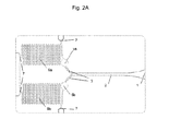
- Figures 2 and 2A show a top view of different embodiments of the microfluidic device of the invention, said device comprising the components described below.
- Means (1) for introducing a sample of fluid medium mainly consisting of an inlet port.
- This inlet port is coupled to a distribution capillary channel (2), followed by a channel bifurcation (3) which splits the distribution channel (2) into a first (6a) and a second region (6b), which permit said fluid medium to flow along a length of said regions.
- the distribution channel contains a cell filter (only depicted in figure 1 ).
- said first (6a) and second (6b) regions have identical structures.
- Each of said regions (6a, and 6b) comprise, in order from the distribution channel, first an area (5a, 5b) and at least one microfluidic channel, which will be referred to as the scanning area (8) herein.
- the first area (5a) contains a first reagent capable of reacting with said fluid medium, and makes the microfluidic channel in region (6a) function as a reaction channel, while the second area (5b) is either empty or contains a different reagent, so that the microfluidic channel in region (6b) functions as a control channel.
- said first reagent is capable of initiating clotting of said fluid medium.
- More than two regions may be present in the chip.
- One of the regions functions as the reaction channel as explained above, and the other two or more are control channels.
- the blood sample can be capillary driven along control channels where the reaction chambers have specific compounds that provide known and fixed (or narrow band) coagulation times.
- the reaction chambers have specific compounds that provide known and fixed (or narrow band) coagulation times.
- two types of such controls can be incorporated, normalized control and abnormal control, to provide lower and higher references to coagulation times.
- control channels have a different reagent composition from the reagent present in the reaction channel. Therefore in one embodiment, there is a normalized control channel, the reagent present in it can be for example at least one Vitamin K dependent clotting factor. Such clotting factors can come from a dried or lyophilized pool of normal patient plasmas.
- an abnormal control channel which comprises a clotting factor inhibitor such as, heparines, citrates, oxalates, EDTA and the like. Further, it can comprise the same Vitamin K dependent clotting factorsas in the normalized control channel.
- each region (6a, 6b) contains means (7) for venting, most preferably a venting port, which also functions as a stop flow valve.
- the venting ports (7) can be located at other positions along the microfluidic channels.
- venting ports (7) For example, connecting venting ports (7) with flow stops at the exit of the reaction chambers allows that capillary flow speeds up to this point are maximized, as depicted in figure 2A .
- each channel has more than one venting port (7), the venting ports (7) allow to control and modulate the velocity and the flowing properties of the fluid.
- At least a property of the fluid medium is monitored as the fluid medium transits scanning areas (8) of the first (6a), second (6b) and optional third regions. Comparison between said properties in said different regions enables detection of the moment when the reaction in the first region (6a) has taken place and the determination of the clotting time for the fluid sample.
- the regions are preferably capillary channels.
- L L(t)
- the device must be designed and the size of the channels chosen according to the existing relation (4) between geometrical parameters of the channels, a, b and L, the volume of sample required and the maximum clotting time.
- the clotting time can be determined or controlled through comparison of the measured property of the sample with the theoretical predicted value.
- the clotting time can be determined as the instant when the monitored clotting curve deviates beyond a particular threshold from the theoretical curves from equations (3).
- a few mathematical operations can be applied so that such deviation depends only on the qualitative flow dynamic behaviour and not on the quantitative one. Two different but analogous approaches are described as follows:
- L(t) is a power function of time.
- L t Kt 0.5
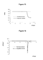
- the monitored curve (coagulation channel) and theoretical curve are plotted on the graph depicted in figure 13 .
- the quantitative term is log K and the qualitative is 0,5 log t .
- the decay from the constant value beyond a predefined threshold in either the velocity dY du or acceleration d 2 ⁇ Y du 2 curves determines the clotting time.
- the above mentioned operations are the mathematical basis of an algorithm that allows the clotting time determination through only one independent coagulation channel.
- the microfluidic chip of the present invention is designed so that flowing blood has a predominant Newtonian behaviour prior clotting. Deviation from this behaviour is only due to the pseudo-plastic effect, which can appear at low flow rates. If this occurs, the method still applies and works reasonably well because such pseudo-plastic effect is much weaker than the clotting effect, and can be distinguished on the acceleration curves.
- This curve is proportional to viscosity ( ⁇ ), as can be derived from equation (3).
- the following steps (2, 3 and 4) are applied identically as before (i.e. logarithm application, first derivative and second derivative), so that velocity and acceleration curves are constructed.
- the theoretical approach described above can also be employed for quality control by correlating the test curves with the theoretical predictions.
- the blood sample flow prior to clotting should lie close to the mentioned linear behaviour. Any significant deviation from such behaviour can be detected and processed by the flow monitoring system and processor, providing a test cancellation order.
- the fluid medium is blood, preferably capillary whole blood from patient fingerpricking, and calibrated plasma with known clotting times can be used for external quality control.
- the reagent capable of reacting with said fluid medium is a clotting reagent, more preferably a tissue factor or thromboplastin.
- the device and method of the invention are particularly suited to determine the Prothrombin Time, i.e. the time elapsed between clotting activation and start of clotting.
- the device can be designed according to standard INR values; the recommended highest INR range is about 8, which also means PT about 100 seconds.
- the dimensions required for reaching such a maximum INR are shown in Table 1.
- the required dimensions and total volumes "V t " of different conduits designs are governed by equation (3).
- Table 1. Required lengths and total volumes "Vt" of different conduits designs for reaching such maximum INR range 100 sec.
- a (mm) b (mm) L (mm) V t ( ⁇ L) Microfluidic design 0.08 0.08 150 1.0 Microfluidic design 0.125 0.125 250 3.9
- the shape and the dimensions of the channels according to the present invention allow the determination of the clotting time of a blood sample of no more than 15 ⁇ l, and the total volume allocated when all the circuits are filled is less than 10 ⁇ l allowing a remaining volume within the inlet port, necessary to fix the dewetting meniscus at the inlet port.
- the microfluidic channels allow a continuous flow, lasting from several seconds to more than a hundred seconds, allowing the PT determination around a long time range.
- the chip and method of the invention allow the measurement of accurate clotting times and INR determination with low amounts of blood sample, preferably below 10 ⁇ l, more preferably below 5 ⁇ l, and most preferably with about 1 ⁇ l or less. This is very important for the convenience of the patient.
- the length of the capillary channels (6a, 6b) should be large enough to enable the reaction of the reagent with the fluid to be completed before the fluid front reaches the end of the channel.
- the capillary channels (6a, 6b) are in a curved shape, most preferably having a serpentine shaped track, in order to minimize the area of the device while maintaining the length of the channels.
- the preferred cross-section of the channels is rectangular due to manufacturing constrains, allowing a pure 2D geometry, which simplifies the mould fabrication processes.
- the specific dimensions have to be carefully calculated as the flow dynamic, and total volume employed is very sensitive to channel dimensions. As shown herein, dimension values well above 100 ⁇ m require very large channel lengths to permit flow durations up to the highest clotting times, and higher blood sample volumes are required. With a microfluidic design, or in other words, channel cross section dimensions about 100 ⁇ m or less, channel lengths can be reduced with little blood usage. In addition the size of the chip and its cost are also reduced considerably.
- a and b are preferably between 30 to 125 ⁇ m, more referably beween 50 and 100 ⁇ m, and even more preferably of about 80 ⁇ m.
- the dimensions of the area containing the reagent, preferably a reaction cell, must be appropriate to allow enough volume for dispensing the reagent in liquid state.
- the design has to be defined so the diffusion time permits reaching enough reagent concentration in order to maximize the activated blood volume. This can be achieved by maximizing the surface to volume ratio within the reaction chamber.
- the footprint chamber design should be circular for adapting to droplet dispensed shape, with dimensions between 1 to 4 mm in diameter and height between 40 to 150 ⁇ m. More preferably, the diameter is about 1.5 mm and height is about 80 ⁇ m.
- the height dimension of the distribution channel is preferably between 150 ⁇ m and 350 ⁇ m, more preferably about 250 ⁇ m.
- the blood inlet port is preferably the gap left between the cover and base substrates at the edge of the chip, on the distribution channel, and therefore can have the height of said distribution channel.
- Volume allocated on the distribution channel should be slightly larger than the volume allocated in the subsequent capillary structure, so that once the distribution channel is completely filled with fluid it can never be emptied. This volume defines the minimum test sample volume requirement.
- the flow rate Q can be modified through the introduction of passive flow control valves by modifying the cross section of the microfluidic channels, for example, by narrowing segments of the microfluidic channels or by introducing tapered microfluidic channels.
- the present invention requires applying a sample of blood or plasma to the inlet port, through which the blood or plasma enters the sample distribution channel, along which the same blood sample or plasma is split into a reaction/clotting channel and one or more control channels.
- L y L' are respectively the clotting and control positions.
- the split flows have nearly identical motion dynamics until the coagulation is initiated in the clotting channel. This instant, when the first blood clotting occurs, is identified as the Prothrombin Time, and induces a sudden increase in viscosity. At this instant the flow dynamics along the clotting channel is decelerated with respect to the control channel(s).
- the flow front position as a function of time
- the derivative of the position with time which can be referred to as the flow front velocity
- V V tm
- V ⁇ V ⁇ tm
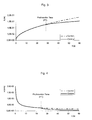
- PT can be determined by defining a suitable threshold " ⁇ " for the difference between the velocities V(t m )-V'(t m ). Prior to PT, the viscosity is constant and the flow front positions and velocities have minor differences as schematically shown in figure 5 .
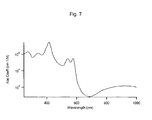
- the coefficient of absorption of blood is plotted in figure 7 . It can be seen that it absorbs especially at 400 nm, and also around the green (530 nm).
- the serpentine is illuminated with a LED and transmitted light is detected with the photodiode.
- the moving flow front linearly increases the absorption and thus the intensity detected is accordingly reduced.
- With a signal amplifier it is possible to monitor tiny flow position increments.
- a LED and a photodiode, both low cost, from readily available distributors have been selected.
- the LED has 3 mm size and emits within a 20° angle.
- the emission spectrum of the LED and the response curve of the photodiode which is a standard Silicon one but also optimized to detect the greenish wavelengths, can be shown in figures 8 and 9 .
- the intensity signal detected by the photodiode can be obtained.
- the Intensity signal, plotted in Figure 10 also contains a dark current random noise simulation of 20picoA, as specified by the manufacturer. This curve corresponds to a channel section of 250x250 ⁇ m.
- the system employs a similar configuration but substituting the detection device.
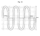
- the LED system can be similar to the one defined in the previous case. Interestingly, in this case no high sensitivity is required, as each cell or pixel within the CCD is to detect the presence of absence of flow in this position. As shown in figure 12 , by superposing the CCD effective area of a standard with the serpentine, the mapped image would allow the identification of the flow front position, with enough resolution and time response (>1KHz).
- This technique requires image data processing, so that from a blurry image the meniscus position can be identified. This increases the complexity of the monitoring system. However, and in contrast with the photodiode detection scheme, the sensitivity of each cell or pixel is less stringent, which in this sense will favour the CCD detection scheme.
- optical means such as a lens
- optical means such as a lens
- Commercial rigid blocks, integrating lens and sensor are available nowadays at very low cost, such as the miniature cameras that are supplied to the mobile industry. These blocks measure just a few millimetres and thus allows very compact and thin integration into portable systems, such as the portable coagulometer.
- the detected signal is processed by the microprocessor with embedded software. Dynamic flow data curves are generated and the algorithms are employed for coagulation time determination and also for various quality controls.
- the chip (test strip) and method of the invention have another significant advantage, in that the same detection means can be used for monitoring the sample fluid flow and for fulfilling various quality control task.
- the detection means is provided through artificial vision system, such as CCD/CMOS sensor or microcamera
- three main quality controls usual in test strips for coagulameters, can be performed through field of view image processing of such a vision system:
- ambient conditions such as temperature and humidity can be monitored through colour sensitive compounds to these factors.
- the selected compounds undergo an irreversible colour change when subjected to temperature and humidity thresholds, signalling a deficient chip. They can be added directly on the reaction chambers, on the base substrate or on the cover surface, under the detector's field of view.
- a combination of different sensitive compounds can be used to this end. Examples of such compounds as sensible temperature compounds: Leuco dyes, Oxazines, Crystal violet lactone, phenolphthalein and the like.
- Metallic salts as sensible moisture compounds cobalt chloride, calcium sulfate and the like. N-oxide or Nitroso compounds as both temperature and moisture sensible compounds.
- the measuring device such as portable coagulometer
- External quality control calibrated plasmas with known clotting times, commercially available for performing INR and PT test calibrations, can be used as external quality control, so that the whole portable coagulometer system can be evaluated.
- the artificial vision system is adjusted to allow detection of the flowing plasmas.
- plasma is a nearly transparent fluid, little adjustment of the illumination led system and image processing is required to effectively track plasma flow, since moving plasma is recognized like a grey shadow advancing along bright channels.
- Printed Codebar printed code carrying among other relevant information calibration data, traceability data and expiry date. Standard data matrix codes of a few millimiters dimensions used in this kind of test strips can be printed onto the chip's cover layer or onto a transparent label.
- the suitable detecting and/or monitoring means described above are comprised in an external device (coagulometer) which comprises a slot for receiving the microfluidic device of the invention and is designed to cooperate with said microfluidic device.
- an external device coagulometer
- the external device comprises means for processing the data delivered by the detecting and/or monitoring means and produces a signal output into a displaying means.
- the present microfluidic device can be easily manufactured with current plastic replication technologies and assembling techniques.
- the assembly is formed by two sealed components: the lower substrate, where the microstructures are patterned and the top substrate or cover lid, as illustrated in Figure 1 .
- the materials suitable for both the lower substrate and the cover layer of the device are a range of polymer, thermoset and/or thermoplastic materials should have good optical properties and good dimensional stability.
- polymer thermoset and/or thermoplastic materials should have good optical properties and good dimensional stability.
- COC COC, PMMA, PC, PSU, SAN, PETG, PS and PP can be used.
- the lower substrate can be easily replicated with a range of technologies, available today, and with very high accuracies, allowing low microfeature tolerances.
- the most relevant current techniques for said patterning step are microinjection moulding, hot embossing and soft lithography imprinting.
- the sealing step can be performed with a number of well known techniques such as thermal compression bonding, adhesive bonding, plasma activated bonding, ultrasonic bonding, laser welding and others.
- the cover is preferably a hydrophilic film. It is preferably transparent, to allow accurate monitoring of the fluid flow.
- hydrophilic films provide very cost-effective means that enable both sealing and channel hydrophilization, avoiding the surface treatment step.
- the production technique consists of standard lamination processes, which can require pressure and temperature control. Other production techniques are embossing or pressing processes.
- the Reaction chambers can allocate a number of dry-reagent compounds for various purposes.
- the main compound is thromboplastin to initiate the coagulation cascade. Due to the tiny dimensions of the reaction chamber high performance compounds can be added without significantly increasing the cost of production.
- Human thromboplastin recombinants have extremely useful properties in terms of solubilization and sensitivity due to their chemical purity. The former property has been traditionally enhanced by the use of specific additives. Under the present invention's design, a fraction of a microliter of human recombinant factor can be dispensed, showing excellent results in terms of solubilization and sensitivity.
- a number of additional agents play a role in the proper functioning of the dry reagent. They may be employed not only for rapid solubilization, but also for control diffusion parameters, improving fabrication steps and reagent stability, or for addressing the following issues:
- the dry-reagents can be applied on the reaction chamber or alternatively onto the cover substrate, through a number of well known techniques: liquid drop dispensing, gel dispensing, jet dispensing, screen printing, blade coating, selective spraying and film casting.
- the dispensing step is followed by a drying step.
- dry reagent is dispensed in liquid state onto the reaction chamber forming a droplet occupying most of the chamber that upon drying becomes a thin dry-reagent layer.
- both the manufacturing method and the chip (test strip) so fabricated are extremely simple, no embedded components are required, such as electrodes or any form of multilayer structures.
- the presented manufacturing techniques allow low cost production, so that cheap disposable devices can be produced.
- the current invention through its microfluidic design, provides very sensitive and accurate means for clotting time determination.
- the clotting time (such as the Prothrombin Time) relates to the moment when the insoluble fibrin molecules start to polymerise that later produces a "mesh" that forms the clot.
- the formation of fibrin polymers typically of the order of a few micrometers, leads to an abrupt increase on the apparent viscosity of the flowing blood, specially when the channel cross-section becomes as tiny as in the current microfluidic design. In terms of accuracy and sensitivity, this device offers the previously mentioned advantages with respect to previous devices for clotting time determination.
- the combination of chip and measuring device of the invention provides combined advantages.
- the use of single optical detection means allows to simultaneously combine the detection of fluid flow changes and different quality controls. This means that the portable measuring device will be less complex and more compact, using standard components. In fact the measuring device can have the size of a mobile telephone.
- the flow monitoring is made continuously with a high frequency sampling. In this way, the very instant when the clot formation has the first decelerating effect on blood flow can be accurately determined.
Landscapes
- Health & Medical Sciences (AREA)
- Life Sciences & Earth Sciences (AREA)
- Engineering & Computer Science (AREA)
- Chemical & Material Sciences (AREA)
- Hematology (AREA)
- Biomedical Technology (AREA)
- Physics & Mathematics (AREA)
- Immunology (AREA)
- Analytical Chemistry (AREA)
- General Health & Medical Sciences (AREA)
- Urology & Nephrology (AREA)
- Molecular Biology (AREA)
- Pathology (AREA)
- General Physics & Mathematics (AREA)
- Biochemistry (AREA)
- Food Science & Technology (AREA)
- Medicinal Chemistry (AREA)
- Ecology (AREA)
- Biophysics (AREA)
- Microbiology (AREA)
- Cell Biology (AREA)
- Biotechnology (AREA)
- Clinical Laboratory Science (AREA)
- Chemical Kinetics & Catalysis (AREA)
- Dispersion Chemistry (AREA)
- Quality & Reliability (AREA)
- Investigating Or Analysing Biological Materials (AREA)
- Investigating Or Analyzing Non-Biological Materials By The Use Of Chemical Means (AREA)
- Investigating Or Analysing Materials By The Use Of Chemical Reactions (AREA)
- Investigating Or Analysing Materials By Optical Means (AREA)
- Automatic Analysis And Handling Materials Therefor (AREA)
- Acyclic And Carbocyclic Compounds In Medicinal Compositions (AREA)
- Reciprocating Pumps (AREA)
- Measuring Or Testing Involving Enzymes Or Micro-Organisms (AREA)
Claims (29)
- Mikrofluidik-Vorrichtung zur Bestimmung der Gerinnungszeit in einem flüssigen Medium, wie Blut oder Plasma, wobei die Vorrichtung Folgendes umfasst:- eine Einrichtung (1) zum Einführen einer Probe des flüssigen Mediums, gekoppelt an einen Verteilungskapillarkanal (2); und- einen ersten Bereich (6a), der an die Einrichtung (1) zum Einführen einer Probe gekoppelt ist, zum Fließenlassen des flüssigen Mediums entlang einer Strecke des ersten Bereichs;- eine erste Zone (5a) am Anfang des ersten Bereichs, die ein Reagens enthält, das mit dem flüssigen Medium reagieren kann;- einen zweiten Bereich (6b), der ebenfalls an die Einrichtung (1) zum Einführen einer Probe gekoppelt ist, zum Fließenlassen des flüssigen Mediums entlang einer Strecke des zweiten Bereichs;- wobei der zweite Bereich (6b) kein Reagens enthält, das mit dem flüssigen Medium reagieren kann; oder- wobei es am Anfang des zweiten Bereichs (6b) eine zweite Zone (5b) gibt, die ein Reagens enthält, das mit dem flüssigen Medium reagieren kann und von dem Reagens der ersten Zone (5a) verschieden ist;- dadurch gekennzeichnet, dass jeder der Bereiche (6a) und (6b) in der Reihenfolge vom Verteilungskanal (2) her gesehen zuerst die Zonen (5a) und (5b) und wenigstens einen Mikrofluidik-Kanal, bei dem es sich um die Abtastzone (8) handelt, umfasst.
- Mikrofluidik-Vorrichtung gemäß Anspruch 1, dadurch gekennzeichnet, dass jeder der Bereiche (6a, 6b) aus wenigstens einem Mikrofluidik-Kanal besteht.
- Mikrofluidik-Vorrichtung gemäß Anspruch 2, dadurch gekennzeichnet, dass die Mikrofluidik-Kanäle (6a, 6b) Kapillarkanäle sind, wobei die Oberflächen der Kanäle hydrophil sind und die Kapillarkraft als einzige Kraft zum Bewegen des flüssigen Mediums wirkt.
- Mikrofluidik-Vorrichtung gemäß einem der Ansprüche 1 bis 3, dadurch gekennzeichnet, dass jeder der Bereiche eine Einrichtung (7) zur Entlüftung enthält.
- Mikrofluidik-Vorrichtung gemäß Anspruch 4, wobei die Einrichtung zur Entlüftung aus einer Entlüftungsöffnung (7) besteht, die als Absperrventil fungiert.
- Vorrichtung gemäß einem der Ansprüche 1 bis 5, dadurch gekennzeichnet, dass die erste Zone des ersten Bereichs aus einer Reaktionszelle (5a) besteht, die ein Reagens enthält, das die Gerinnung des flüssigen Mediums einleiten kann.
- Mikrofluidik-Vorrichtung gemäß einem der Ansprüche 1 bis 6, dadurch gekennzeichnet, dass die zweite Zone des zweiten Bereichs aus einer Reaktionszelle (5b) besteht, die ein Reagens enthält, das die Gerinnung des flüssigen Mediums hemmen kann.
- Mikrofluidik-Vorrichtung gemäß einem der Ansprüche 1 bis 7, dadurch gekennzeichnet, dass die Vorrichtung weiterhin einen dritten Bereich umfasst, der ebenfalls an die Einrichtung (1) zum Einführen einer Probe gekoppelt ist, zum Fließenlassen des flüssigen Mediums entlang einer Strecke des dritten Bereichs, wobei es am Anfang des dritten Bereichs eine dritte Zone gibt, die ein Reagens enthält, das mit dem flüssigen Medium, welches von dem Reagens der ersten (5a) oder zweiten (5b) Zone verschieden ist, reagieren kann.
- Mikrofluidik-Vorrichtung gemäß einem der Ansprüche 1 bis 8, dadurch gekennzeichnet, dass die Einrichtung zum Einführen einer Probe aus einer Einlassöffnung (1) besteht, die über einen Verteilungskanal (2) und anschließend eine Kanalgabelung (3), die in den ersten, zweiten und gegebenenfalls dritten Bereich abzweigt (4), mit dem ersten und zweiten Bereich (6a, 6b) und gegebenenfalls dritten Bereich gekoppelt ist.
- Mikrofluidik-Vorrichtung gemäß einem der Ansprüche 1 bis 9, dadurch gekennzeichnet, dass der erste, zweite und gegebenenfalls dritte Bereich (6a, 6b) eine gekrümmte Form haben.
- Mikrofluidik-Vorrichtung gemäß einem der Ansprüche 1 bis 10, dadurch gekennzeichnet, dass der erste, zweite und gegebenenfalls dritte Bereich (6a, 6b) aus Kanälen bestehen, die einer schlangenförmigen Bahn folgen.
- Mikrofluidik-Vorrichtung gemäß einem der Ansprüche 1 bis 11, dadurch gekennzeichnet, dass die Kanäle einen rechteckigen Querschnitt haben.
- Mikrofluidik-Vorrichtung gemäß einem der Ansprüche 1 bis 12, dadurch gekennzeichnet, dass die Kanäle aus einer Kombination von Segmenten mit unterschiedlichen Querschnitten bestehen.
- Mikrofluidik-Vorrichtung gemäß einem der Ansprüche 1 bis 13, dadurch gekennzeichnet, dass es sich bei dem Reagens in Zone (5a) um Thromboplastin handelt und die Gerinnungszeit der Prothrombinzeit entspricht.
- Mikrofluidik-Vorrichtung gemäß einem der Ansprüche 1 bis 14, dadurch gekennzeichnet, dass der erste Bereich als Gerinnungskanal (6a) wirkt und der zweite Bereich als Kontrollkanal (6b) wirkt und dass die beiden Bereiche eine identische Struktur haben.
- Mikrofluidik-Vorrichtung gemäß einem der Ansprüche 1 bis 14, dadurch gekennzeichnet, dass der erste Bereich als Gerinnungskanal (6a) wirkt und der zweite und dritte Bereich als Kontrollkanäle wirken und dass alle drei Bereiche eine identische Struktur haben.
- Mikrofluidik-Vorrichtung gemäß den Ansprüchen 1 bis 16, die weiterhin optische Teile zur Qualitätskontrolle umfasst.
- Koagulometer-Vorrichtung, umfassend:- einen Schlitz zum Einführen einer Mikrofluidik-Vorrichtung gemäß den Ansprüchen 1 bis 17;- optische Einrichtungen zum kontinuierlichen Nachweisen und/oder Überwachen der Position der Front des flüssigen Mediums in jedem der Bereiche und/oder seiner Geschwindigkeit; und- eine Einrichtung zum Verarbeiten der von den Nachweis- und/oder Überwachungseinrichtungen gelieferten Daten und zum Bestimmen der Gerinnungszeit des flüssigen Mediums;wobei die optischen Einrichtungen auch die Qualitätskontrollmerkmale auf der Mikrofluidik-Vorrichtung messen oder lesen.
- Koagulometer-Vorrichtung gemäß Anspruch 18, dadurch gekennzeichnet, dass die Verarbeitungseinrichtung eine Einrichtung zum Vergleichen der Eigenschaft oder Eigenschaften in jedem der zwei oder drei Bereiche umfasst.
- Koagulometer-Vorrichtung gemäß einem der Ansprüche 18 bis 19, dadurch gekennzeichnet, dass die Verarbeitungseinrichtung eine Einrichtung zum Nachweisen des Zeitpunkts, wenn der Unterschied zwischen der oder den Eigenschaften im ersten Kanal (6a) und der oder den Eigenschaften im zweiten Kanal (6b) und/oder dritten Kanal eine vorbestimmte Schwelle erreicht, umfasst.
- Koagulometer-Vorrichtung gemäß einem der Ansprüche 18 bis 20, dadurch gekennzeichnet, dass die Nachweis- und/oder Überwachungseinrichtung eine Einrichtung zum Beleuchten jedes der Bereiche und eine Einrichtung zum Analysieren des von jedem der Bereiche durchgelassenen oder reflektierten Lichts umfasst.
- Koagulometer-Vorrichtung gemäß Anspruch 21, dadurch gekennzeichnet, dass die Beleuchtungseinrichtung wenigstens eine LED umfasst und die Analyseeinrichtung wenigstens einen optischen Sensor umfasst.
- Koagulometer-Vorrichtung gemäß Anspruch 22, dadurch gekennzeichnet, dass die Analyseeinrichtung wenigstens eine Linse umfasst.
- Verfahren zur Bestimmung der Gerinnungszeit in einem flüssigen Medium, wie Blut oder Plasma, umfassend die folgenden Schritte:- Einführen einer Probe des flüssigen Mediums in eine Mikrofluidik-Vorrichtung gemäß den Ansprüchen 1 bis 17, die einen ersten und einen zweiten Bereich (6a, 6b) aufweist, wo es entlang einer Strecke fließen kann;- Bereitstellen eines ersten Reagens (5a), das mit dem flüssigen Medium reagieren kann, am Anfang des ersten Bereichs (6a) in der Zone (5a); und- Bereitstellen von keinem Reagens oder eines zweiten Reagens (5b), das von dem ersten Reagens (5a) im ersten Bereich (6a) verschieden ist, im zweiten Bereich (6b) in der Zone (5b);- kontinuierliches Überwachen wenigstens einer Eigenschaft des flüssigen Mediums im ersten Bereich (6a) und im zweiten Bereich (6b) mit einer optischen Einrichtung;- Vergleichen wenigstens einer Eigenschaft des flüssigen Mediums im ersten Bereich (6a) mit wenigstens derselben Eigenschaft des flüssigen Mediums im zweiten Bereich (6b) oder mit einem theoretischen Wert dieser Eigenschaft.
- Verfahren zur Bestimmung der Gerinnungszeit in einem flüssigen Medium, wie Blut oder Plasma, gemäß Anspruch 24, dadurch gekennzeichnet, dass der Vergleich wenigstens der Eigenschaft des flüssigen Mediums im ersten Bereich gegen wenigstens eine Eigenschaft des flüssigen Mediums im zweiten Bereich (6b) vorgenommen wird.
- Verfahren zur Bestimmung der Gerinnungszeit in einem flüssigen Medium, wie Blut oder Plasma, gemäß Anspruch 24, dadurch gekennzeichnet, dass der Vergleich wenigstens der Eigenschaft des flüssigen Mediums im ersten Bereich mit einem theoretischen Wert dieser Eigenschaft vorgenommen wird.
- Verfahren zur Bestimmung der Gerinnungszeit in einem flüssigen Medium, wie Blut oder Plasma, gemäß Anspruch 24 oder 25, dadurch gekennzeichnet, dass das Verfahren einen Qualitätskontrollschritt beinhaltet, der das Korrelieren der überwachten Eigenschaften mit den theoretischen Kurven umfasst.
- Verfahren zur Herstellung einer Mikrofluidik-Vorrichtung gemäß einem der Ansprüche 1 bis 17 zur Bestimmung der Gerinnungszeit in einem flüssigen Medium, wie Blut oder Plasma, umfassend die folgenden Schritte:- Bereitstellen eines ersten Substrats;- Herstellen einer Mikrostruktur, die einer Mikrofluidik-Vorrichtung gemäß einem der Ansprüche 1 bis 17 entspricht, in dem ersten Substrat;Bereitstellen eines zweiten Substrats; und dichtes Auflegen des zweiten Substrats auf das strukturierte erste Substrat, so dass das zweite Substrat als Abdeckung wirkt.
- Verfahren gemäß Anspruch 28, wobei das zweite Substrat eine hydrophile Folie ist.
Priority Applications (4)
| Application Number | Priority Date | Filing Date | Title |
|---|---|---|---|
| PL08804568T PL2201365T3 (pl) | 2007-09-20 | 2008-09-22 | Mikrostrumieniowe urządzenie i sposób oznaczania czasu krzepnięcia płynu |
| SI200830224T SI2201365T1 (sl) | 2007-09-20 | 2008-09-22 | Mikrofluidna naprava in postopek za določanje koagulacijskega časa fluidov |
| EP11155204A EP2325636A1 (de) | 2007-09-20 | 2008-09-22 | Verfahren zur Flüssigkeitsgerinnungs-Zeitbestimmung |
| EP08804568A EP2201365B1 (de) | 2007-09-20 | 2008-09-22 | Mikrofluidik-vorrichtung und verfahren zur bestimmung der flüssigkeitsgerinnungszeit |
Applications Claiming Priority (3)
| Application Number | Priority Date | Filing Date | Title |
|---|---|---|---|
| EP07380258A EP2040073A1 (de) | 2007-09-20 | 2007-09-20 | Mikrofluidische Vorrichtung und Verfahren zur Flüssigkeitsgerinnungs-Zeitbestimmung |
| PCT/EP2008/062642 WO2009037361A1 (en) | 2007-09-20 | 2008-09-22 | Microfluidic device and method for fluid clotting time determination |
| EP08804568A EP2201365B1 (de) | 2007-09-20 | 2008-09-22 | Mikrofluidik-vorrichtung und verfahren zur bestimmung der flüssigkeitsgerinnungszeit |
Related Child Applications (1)
| Application Number | Title | Priority Date | Filing Date |
|---|---|---|---|
| EP11155204.8 Division-Into | 2011-02-21 |
Publications (2)
| Publication Number | Publication Date |
|---|---|
| EP2201365A1 EP2201365A1 (de) | 2010-06-30 |
| EP2201365B1 true EP2201365B1 (de) | 2011-04-06 |
Family
ID=39135160
Family Applications (3)
| Application Number | Title | Priority Date | Filing Date |
|---|---|---|---|
| EP07380258A Withdrawn EP2040073A1 (de) | 2007-09-20 | 2007-09-20 | Mikrofluidische Vorrichtung und Verfahren zur Flüssigkeitsgerinnungs-Zeitbestimmung |
| EP08804568A Active EP2201365B1 (de) | 2007-09-20 | 2008-09-22 | Mikrofluidik-vorrichtung und verfahren zur bestimmung der flüssigkeitsgerinnungszeit |
| EP11155204A Ceased EP2325636A1 (de) | 2007-09-20 | 2008-09-22 | Verfahren zur Flüssigkeitsgerinnungs-Zeitbestimmung |
Family Applications Before (1)
| Application Number | Title | Priority Date | Filing Date |
|---|---|---|---|
| EP07380258A Withdrawn EP2040073A1 (de) | 2007-09-20 | 2007-09-20 | Mikrofluidische Vorrichtung und Verfahren zur Flüssigkeitsgerinnungs-Zeitbestimmung |
Family Applications After (1)
| Application Number | Title | Priority Date | Filing Date |
|---|---|---|---|
| EP11155204A Ceased EP2325636A1 (de) | 2007-09-20 | 2008-09-22 | Verfahren zur Flüssigkeitsgerinnungs-Zeitbestimmung |
Country Status (22)
| Country | Link |
|---|---|
| US (2) | US8961903B2 (de) |
| EP (3) | EP2040073A1 (de) |
| JP (2) | JP5579607B2 (de) |
| KR (2) | KR101439404B1 (de) |
| CN (2) | CN101868723B (de) |
| AT (1) | ATE504832T1 (de) |
| AU (1) | AU2008300501B2 (de) |
| BR (2) | BR122013004885B8 (de) |
| CA (2) | CA2803927C (de) |
| DE (1) | DE602008006108D1 (de) |
| DK (1) | DK2201365T3 (de) |
| ES (1) | ES2364568T3 (de) |
| HR (1) | HRP20110399T1 (de) |
| IL (2) | IL204571A (de) |
| MX (1) | MX2010003037A (de) |
| NZ (2) | NZ600747A (de) |
| PL (1) | PL2201365T3 (de) |
| PT (1) | PT2201365E (de) |
| RU (2) | RU2477480C2 (de) |
| SI (1) | SI2201365T1 (de) |
| WO (1) | WO2009037361A1 (de) |
| ZA (2) | ZA201001950B (de) |
Cited By (1)
| Publication number | Priority date | Publication date | Assignee | Title |
|---|---|---|---|---|
| US9651567B2 (en) | 2013-05-14 | 2017-05-16 | Cgt Enterprises, Llc | Test strips for determining coagulation factor activities |
Families Citing this family (94)
| Publication number | Priority date | Publication date | Assignee | Title |
|---|---|---|---|---|
| EP2040073A1 (de) | 2007-09-20 | 2009-03-25 | Iline Microsystems, S.L. | Mikrofluidische Vorrichtung und Verfahren zur Flüssigkeitsgerinnungs-Zeitbestimmung |
| WO2009149257A1 (en) | 2008-06-04 | 2009-12-10 | The University Of Chicago | The chemistrode: a plug-based microfluidic device and method for stimulation and sampling with high temporal, spatial, and chemical resolution |
| CN102112048B (zh) * | 2008-08-06 | 2013-12-11 | 霍夫曼-拉罗奇有限公司 | 具有用于消耗品的紧凑式条形码读取器的医疗系统 |
| US20120077260A1 (en) * | 2009-03-30 | 2012-03-29 | Fraunhofer Usa, Inc. | Reservoir-buffered mixers and remote valve switching for microfluidic devices |
| CN102448612B (zh) * | 2009-04-13 | 2014-12-03 | 精密公司 | 微流体临床分析器 |
| JP5816613B2 (ja) * | 2009-04-23 | 2015-11-18 | ダブリン シティ ユニバーシティ | 凝固をモニタするための側方流動分析装置及びその方法 |
| RU2583068C2 (ru) * | 2010-01-24 | 2016-05-10 | Институт Хеми Физичней Польской Академии Наук | Система и способ автоматического образования жидких смесей и работы с ними |
| US9132423B2 (en) | 2010-01-29 | 2015-09-15 | Micronics, Inc. | Sample-to-answer microfluidic cartridge |
| KR20130010483A (ko) * | 2010-03-30 | 2013-01-28 | 씨 에이 카시소 아게 | 검사액의 응고 특성의 측정을 위한 조성물 |
| JP5592144B2 (ja) * | 2010-04-27 | 2014-09-17 | 日本電信電話株式会社 | 凝固活性測定装置および測定方法 |
| EP2596347B1 (de) | 2010-07-22 | 2017-09-06 | Hach Company | Alkalinitätsanalyse mittels lab-on-chip |
| EP2490020A1 (de) | 2011-02-18 | 2012-08-22 | Koninklijke Philips Electronics N.V. | Messchip, mikrofluidische Vorrichtung und Verfahren zur Herstellung des Messchips |
| DE102011004805A1 (de) * | 2011-02-28 | 2012-08-30 | Siemens Aktiengesellschaft | Miniaturisierte magnetische Durchflusszytometrie |
| GB201109203D0 (en) * | 2011-06-01 | 2011-07-13 | Carclo Technical Plastics Ltd | Fluid flow control |
| FI124169B (fi) * | 2011-06-14 | 2014-04-15 | Sandvik Mining & Constr Oy | Menetelmä poraussuunnitelman laatimiseksi |
| JP5730396B2 (ja) * | 2011-07-28 | 2015-06-10 | 京セラ株式会社 | バイオセンサ |
| KR101193566B1 (ko) * | 2011-08-10 | 2012-10-22 | 고려대학교 산학협력단 | 마이크로칩 기반 혈소판 복합기능 검사 장치 |
| GB201113992D0 (en) | 2011-08-12 | 2011-09-28 | Molecular Vision Ltd | Device |
| JP5607593B2 (ja) * | 2011-09-05 | 2014-10-15 | 日本電信電話株式会社 | 凝固活性測定装置、測定チップおよび測定方法 |
| JP5592324B2 (ja) * | 2011-09-05 | 2014-09-17 | 日本電信電話株式会社 | 凝固活性測定装置および測定方法 |
| EP2788735B1 (de) * | 2011-12-06 | 2019-02-06 | Medtronic Inc. | Gerinnselschutz- und detektionsalgorithmus für aktivierte gerinnungszeittests |
| US9518905B2 (en) | 2012-01-16 | 2016-12-13 | Abram Scientific, Inc. | Methods, devices, and systems for measuring physical properties of fluid |
| JP6335802B2 (ja) * | 2012-03-12 | 2018-05-30 | バイオサーフィット、 ソシエダッド アノニマ | 液体試料イメージング装置及び方法 |
| US9180449B2 (en) | 2012-06-12 | 2015-11-10 | Hach Company | Mobile water analysis |
| US9709579B2 (en) * | 2012-06-27 | 2017-07-18 | Colorado School Of Mines | Microfluidic flow assay and methods of use |
| US9291612B2 (en) * | 2012-07-16 | 2016-03-22 | Micropoint Bioscience, Inc. | Determining blood coagulation characteristics using residual accumulative conductive energy |
| KR20150039819A (ko) * | 2012-07-30 | 2015-04-13 | 더 리전트 오브 더 유니버시티 오브 캘리포니아 | 생체 분자 검출 테스트 스트립 설계 |
| EA021562B1 (ru) * | 2012-08-15 | 2015-07-30 | Общество С Ограниченной Ответственностью "Гематологическая Корпорация" | Устройство мониторинга пространственного свертывания крови и ее компонентов |
| JP6010434B2 (ja) * | 2012-11-15 | 2016-10-19 | 株式会社オーイーエムシステム | 体液成分分析装置および体液成分分析方法 |
| USD768872S1 (en) | 2012-12-12 | 2016-10-11 | Hach Company | Cuvette for a water analysis instrument |
| HU1200732D0 (hu) * | 2012-12-14 | 2014-06-30 | Haemoglobal Ltd | Egyszer használatos IVD eszköz a véralvadást jellemzõ INR érték otthoni ellenõrzõ méréséhez |
| US9297816B1 (en) | 2012-12-21 | 2016-03-29 | University Of South Florida | Devices and methods for measuring blood coagulation |
| EP2935559B1 (de) | 2012-12-21 | 2020-09-16 | PerkinElmer Health Sciences, Inc. | Fluoreszenznachweissystem |
| WO2014100743A2 (en) | 2012-12-21 | 2014-06-26 | Micronics, Inc. | Low elasticity films for microfluidic use |
| EP2935908B1 (de) | 2012-12-21 | 2019-08-14 | PerkinElmer Health Sciences, Inc. | Fluidkreisläufe und zugehörige herstellungsverfahren |
| WO2014107240A1 (en) * | 2013-01-03 | 2014-07-10 | Brigham And Women's Hospital, Inc. | System and method for a biomimetic fluid processing |
| JP6093950B2 (ja) * | 2013-04-26 | 2017-03-15 | 東洋インキScホールディングス株式会社 | 液体分析部材用粘着シートおよび液体分析部材 |
| EP2994543B1 (de) | 2013-05-07 | 2018-08-15 | Micronics, Inc. | Vorrichtung zur herstellung und analyse von nukleinsäuren |
| US10386377B2 (en) | 2013-05-07 | 2019-08-20 | Micronics, Inc. | Microfluidic devices and methods for performing serum separation and blood cross-matching |
| EP2994532B1 (de) | 2013-05-07 | 2017-11-15 | Micronics, Inc. | Verfahren zur herstellung von nukleinsäurehaltigen proben mittels tonmineralien und alkalischen lösungen |
| JP6034238B2 (ja) * | 2013-05-17 | 2016-11-30 | 日本電信電話株式会社 | 血液凝固検査方法 |
| US10114032B2 (en) | 2013-05-23 | 2018-10-30 | Nippon Telegraph And Telephone Corporation | Blood coagulation test method |
| US9562914B2 (en) * | 2013-10-16 | 2017-02-07 | President And Fellows Of Harvard College | Microfluidic device for real-time clinical monitoring and quantitative assessment of whole blood coagulation |
| CA2944314C (en) | 2014-03-31 | 2023-09-19 | Brigham And Women's Hospital, Inc. | Systems and methods for biomimetic fluid processing |
| JP6596768B2 (ja) * | 2014-04-08 | 2019-10-30 | 藤森工業株式会社 | 血液性状検査用マイクロチップおよび血液性状検査用装置 |
| WO2015173916A1 (ja) * | 2014-05-14 | 2015-11-19 | 株式会社オーイーエムシステム | 体液成分分析装置および体液成分分析方法 |
| WO2015193076A1 (en) | 2014-06-16 | 2015-12-23 | Koninklijke Philips N.V. | Cartridge for fast sample intake |
| SI3191836T1 (sl) | 2014-09-09 | 2023-04-28 | Perosphere Technologies Inc. | Univerzalni test koagulacije na osnovi mikrofluidnega čipa |
| WO2016043903A1 (en) * | 2014-09-15 | 2016-03-24 | The University Of North Carolina At Chapel Hill | Method for the assembly of functional thermoplastic nanofluidic devices |
| AU2015380619B2 (en) * | 2015-01-30 | 2020-05-21 | Hewlett-Packard Development Company, L.P. | Microfluidic chip for coagulation sensing |
| CN107532131B (zh) * | 2015-04-03 | 2021-11-02 | 国立研究开发法人产业技术总合研究所 | 细胞培养装置及细胞培养方法 |
| US9891209B2 (en) * | 2015-05-29 | 2018-02-13 | C A Casyso Gmbh | Electrode assembly for measurement of platelet function in whole blood |
| RU2018107453A (ru) | 2015-08-10 | 2019-09-12 | Эссенликс Корп. | Устройства для анализов и способы в биологии/химии, предусматривающие упрощенные стадии, образцы небольшого объема, повышенную скорость и простоту применения |
| KR101712429B1 (ko) * | 2015-09-24 | 2017-03-08 | 대한민국(관리부서 질병관리본부장) | 표면-증강 라만 산란 기반의 탄저균 검출용 미세유체칩 및 이를 이용한 탄저균 검출 방법 |
| KR101787407B1 (ko) | 2015-09-30 | 2017-10-18 | 명지대학교 산학협력단 | 미립화된 수용액 방울의 증발냉각을 이용한 미소유체 냉각장치 |
| JP2017078664A (ja) * | 2015-10-21 | 2017-04-27 | 東洋製罐グループホールディングス株式会社 | 免疫学的測定デバイス |
| CN108463708B (zh) * | 2015-11-06 | 2021-10-08 | 密歇根大学董事会 | 基于微滴的微流体流变仪系统 |
| EP3384275A2 (de) | 2015-12-02 | 2018-10-10 | Maastricht University | Verfahren zur bestimmung von hämostase unter querlast |
| WO2017123266A1 (en) | 2016-01-16 | 2017-07-20 | Hewlett-Packard Development Company, L.P. | Blood characteristic measurement |
| CN105842432B (zh) * | 2016-04-29 | 2019-01-22 | 诺泰科生物科技(苏州)有限公司 | 一种血栓弹力仪 |
| US10228381B2 (en) | 2016-07-12 | 2019-03-12 | EMULATE, Inc. | Additive channels |
| EP3582893B1 (de) | 2017-04-20 | 2021-03-31 | Hewlett-Packard Development Company, L.P. | Mikrofluidisches reaktionssystem |
| EP3582892A4 (de) | 2017-04-21 | 2020-03-04 | Hewlett-Packard Development Company, L.P. | Koplanare mikrofluidische manipulation |
| EP3582894A4 (de) | 2017-04-21 | 2020-03-04 | Hewlett-Packard Development Company, L.P. | Mikrofluidischer chip |
| US11278892B2 (en) | 2017-04-21 | 2022-03-22 | Hewlett-Packard Development Company, L.P. | Chip to chip fluidic interconnect |
| WO2018194651A1 (en) | 2017-04-21 | 2018-10-25 | Hewlett-Packard Development Company, | Coplanar fluidic interconnect |
| JP6339274B1 (ja) * | 2017-06-19 | 2018-06-06 | 積水化学工業株式会社 | マイクロ流体デバイス |
| WO2019023508A1 (en) * | 2017-07-28 | 2019-01-31 | Massachusetts Institute Of Technology | METHODS AND DEVICES FOR DETECTION OF ANTICOAGULANTS IN PLASMA AND WHOLE BLOOD |
| CN109839349B (zh) * | 2017-11-28 | 2021-12-07 | 北京碧澄生物科技有限公司 | 检测液体相变的装置和方法 |
| CN108855256B (zh) * | 2018-04-25 | 2020-06-02 | 南开大学 | 一种检测红细胞变形性的微流控芯片及其方法 |
| BR112021000996A2 (pt) | 2018-07-19 | 2021-04-20 | Platelet Biogenesis, Inc. | biorreator de recirculação empilhado |
| WO2020068628A1 (en) | 2018-09-27 | 2020-04-02 | Siemens Healthcare Diagnostics Inc. | Multi-channel device for calculating coagulation characteristics of a patient's liquid test sample and methods of use related thereto |
| AU2019385307A1 (en) | 2018-11-20 | 2021-05-06 | Xa Tek, Inc. | Portable dielectric spectroscopy device |
| US11389799B2 (en) | 2019-01-17 | 2022-07-19 | The Regents Of The University Of Michigan | Microfluidic device for size and deformability measurements and applications thereof |
| TWI873119B (zh) * | 2019-01-29 | 2025-02-21 | 美商伊路米納有限公司 | 流通槽及製備其之方法 |
| WO2020163213A1 (en) | 2019-02-04 | 2020-08-13 | Abram Scientific, Inc. | Fluid property measurement devices and methods |
| BR102019004230A2 (pt) * | 2019-02-28 | 2020-09-08 | Univ Do Vale Do Rio Dos Sinos Unisinos | dispositivo analítico, processo de obtenção e uso do mesmo |
| US12558463B2 (en) | 2019-03-11 | 2026-02-24 | ABC Med Tech Corp. | Portable centrifuge device and method of use |
| CN110057890B (zh) * | 2019-03-26 | 2021-07-30 | 中国科学院苏州生物医学工程技术研究所 | 一种凝血检测芯片和电化学传感器 |
| WO2020231017A1 (ko) * | 2019-05-10 | 2020-11-19 | 포항공과대학교 산학협력단 | 폴리이미드계 필름 기반 합성-모듈, 이의 제조방법 및 이를 이용한 유기포스페이트계 화합물의 대량 생산방법 |
| JP6652673B1 (ja) * | 2019-06-07 | 2020-02-26 | 日本板硝子株式会社 | 反応処理容器 |
| EP3999858B1 (de) | 2019-07-19 | 2025-08-27 | Micropoint Bioscience, Inc. | Fibrinogen-testkassette und verfahren zur bestimmung von fibrinogen |
| KR102229025B1 (ko) * | 2019-07-19 | 2021-03-17 | 전북대학교산학협력단 | 소형 혈액점도측정 키트 및 그 카트리지 |
| USD993443S1 (en) * | 2020-02-04 | 2023-07-25 | Ut-Battelle, Llc | Microfluidic glass chip interface bracket |
| USD989342S1 (en) * | 2020-02-04 | 2023-06-13 | Ut-Battelle, Llc | Microfluidic polymer chip interface bracket |
| KR102885842B1 (ko) * | 2020-03-20 | 2025-11-19 | 주식회사 제우스 | 이중관구조 플로우셀 장치 |
| US20210354135A1 (en) * | 2020-05-13 | 2021-11-18 | The Texas A&M University System | Systems and methods for evaluating an ability of a blood sample to coagulate, clot, and/or occlude |
| US20230414123A1 (en) * | 2020-11-17 | 2023-12-28 | Case Western Reserve University | System and method for measuring blood flow velocity on a microfluidic chip |
| US20240024875A1 (en) * | 2020-11-27 | 2024-01-25 | Fujimori Kogyo Co., Ltd. | Method for manufacturing microchip for blood coagulation test |
| EP4112736A1 (de) * | 2021-07-02 | 2023-01-04 | Vital Signs Solutions Limited | Vorrichtung zum testen von blutplasma |
| CN113702649B (zh) * | 2021-08-25 | 2022-09-02 | 常州工程职业技术学院 | 一种用于测定血液凝结时间的微流体生物芯片 |
| CN116930175A (zh) * | 2022-04-07 | 2023-10-24 | 董嘉 | 一种试剂盒、快速检测凝血分析仪及其进行检测的方法 |
| CN115267213B (zh) * | 2022-08-03 | 2025-07-08 | 武汉纺织大学 | 一种血凝检测微流控芯片、一种血凝检测装置和方法 |
| CN120714721B (zh) * | 2025-08-20 | 2025-11-18 | 山东新华医疗器械股份有限公司 | 一种血栓弹力图微流控芯片及液滴形成方法 |
Family Cites Families (47)
| Publication number | Priority date | Publication date | Assignee | Title |
|---|---|---|---|---|
| US5110727A (en) * | 1987-04-03 | 1992-05-05 | Cardiovascular Diagnostics, Inc. | Method for performing coagulation assays accurately, rapidly and simply, using dry chemical reagents and paramagnetic particles |
| DK15788D0 (da) * | 1988-01-14 | 1988-01-14 | Nordisk Gentofte | Fremgangsmaade og apparat til maaling af fuldblods koagulation |
| JPH0726965B2 (ja) | 1988-01-14 | 1995-03-29 | ノボ‐ノルディスク アクティーゼルスカブ | 血液試料の凝固時間の測定装置 |
| US5039617A (en) | 1989-04-20 | 1991-08-13 | Biotrack, Inc. | Capillary flow device and method for measuring activated partial thromboplastin time |
| JPH03189194A (ja) | 1989-12-20 | 1991-08-19 | Dainippon Printing Co Ltd | 熱転写シート |
| US5154082A (en) | 1991-05-20 | 1992-10-13 | International Technidyne Corporation | Microprocessor-controlled apparatus and method for detecting the coagulation of blood |
| ATE163768T1 (de) | 1991-10-04 | 1998-03-15 | Dade Int Inc | Herstellung von prothrombinzeit-reagenzien aus rekombinantem menschlichem gewebefaktor und sythetischen phospholipiden |
| US5447440A (en) | 1993-10-28 | 1995-09-05 | I-Stat Corporation | Apparatus for assaying viscosity changes in fluid samples and method of conducting same |
| CA2165412A1 (en) | 1994-04-28 | 1995-10-29 | Barry John Woodhams | Calibrator for prothrombin time (pt) assays |
| US5418141A (en) | 1994-05-06 | 1995-05-23 | Avocet Medical, Inc. | Test articles for performing dry reagent prothrombin time assays |
| US5504011A (en) | 1994-10-21 | 1996-04-02 | International Technidyne Corporation | Portable test apparatus and associated method of performing a blood coagulation test |
| JP2002503336A (ja) * | 1997-05-16 | 2002-01-29 | アルバータ リサーチ カウンシル | 微量流通システムおよびその使用方法 |
| AU754536B2 (en) * | 1998-03-19 | 2002-11-21 | Orgenics Biosensors Ltd. | Device for the determination of blood clotting by capacitance or resistance |
| FR2779827B1 (fr) * | 1998-06-10 | 2000-08-11 | Junior Instruments | Appareil d'analyse automatique utilisable pour la determination du temps de coagulation du sang |
| US6830934B1 (en) * | 1999-06-15 | 2004-12-14 | Lifescan, Inc. | Microdroplet dispensing for a medical diagnostic device |
| AU8761098A (en) | 1998-07-29 | 2000-02-21 | Hemosense, Inc. | Method and device for measuring blood coagulation or lysis by viscosity changes |
| BR9815975A (pt) * | 1998-07-31 | 2001-12-04 | Wallace E Carroll | Método e aparelho para a determinação defatores de terapia anticoagulante |
| FI106366B (fi) | 1999-02-17 | 2001-01-31 | Tamfelt Oyj Abp | Suodatinkangas |
| US6733985B1 (en) | 1999-05-19 | 2004-05-11 | International Technidyne Corporation | Preparation of stable liquid and dried synthetic prothrombin time reagents |
| AU6933900A (en) | 1999-09-03 | 2001-04-10 | Roche Diagnostics Corporation | Method, reagent and test cartridge for determining clotting time |
| US6750053B1 (en) | 1999-11-15 | 2004-06-15 | I-Stat Corporation | Apparatus and method for assaying coagulation in fluid samples |
| US6908593B1 (en) * | 2000-03-31 | 2005-06-21 | Lifescan, Inc. | Capillary flow control in a fluidic diagnostic device |
| US6620310B1 (en) | 2000-12-13 | 2003-09-16 | Lifescan, Inc. | Electrochemical coagulation assay and device |
| GB0030929D0 (en) * | 2000-12-19 | 2001-01-31 | Inverness Medical Ltd | Analyte measurement |
| JP2003004752A (ja) * | 2001-06-15 | 2003-01-08 | Minolta Co Ltd | マイクロチップおよび該マイクロチップを用いる検査装置 |
| US6844149B2 (en) * | 2001-06-29 | 2005-01-18 | International Business Machines Corporation | Method, system, and apparatus for measurement and recording of blood chemistry and other physiological measurements |
| WO2003079149A2 (en) * | 2002-03-11 | 2003-09-25 | The University Of Vermont And State Agriculture College | Blood clotting predictor |
| US7901939B2 (en) * | 2002-05-09 | 2011-03-08 | University Of Chicago | Method for performing crystallization and reactions in pressure-driven fluid plugs |
| WO2004044560A1 (en) * | 2002-11-12 | 2004-05-27 | Inverness Medical Switzerland Gmbh | Photometric determination of coagulation time in undiluted whole blood |
| US7291310B2 (en) | 2002-12-17 | 2007-11-06 | The Regents Of The University Of Michigan | Microsystem for determining clotting time of blood and low-cost, single-use device for use therein |
| US7419638B2 (en) * | 2003-01-14 | 2008-09-02 | Micronics, Inc. | Microfluidic devices for fluid manipulation and analysis |
| US7854897B2 (en) * | 2003-05-12 | 2010-12-21 | Yokogawa Electric Corporation | Chemical reaction cartridge, its fabrication method, and a chemical reaction cartridge drive system |
| US7235377B2 (en) | 2003-06-09 | 2007-06-26 | The University Of Vermont And State Agriculture College | Global test of the hemostatic system |
| US7148067B2 (en) | 2004-08-31 | 2006-12-12 | The Board Of Trustees Of The University Of Illinois | Thromboplastin reagents |
| ES2342183T3 (es) * | 2005-08-31 | 2010-07-02 | Egomedical Technologies Ag | Sistema de ensayo de la coagulacion. |
| JP5036547B2 (ja) | 2005-10-18 | 2012-09-26 | 藤森工業株式会社 | 血栓観測装置および血栓観測方法 |
| US20070122849A1 (en) | 2005-11-29 | 2007-05-31 | Peekhaus Norbert T | Rhesus monkey P2X7 purinergic receptor and uses thereof |
| FR2896589B1 (fr) * | 2006-01-25 | 2008-04-25 | Biocode Hycel France Sa Sa | Cuvette d'analyse polyvalente |
| JP2007222072A (ja) * | 2006-02-23 | 2007-09-06 | Tokyo Metropolitan Univ | 化学物質の並行微量分析法 |
| JPWO2007099736A1 (ja) * | 2006-03-03 | 2009-07-16 | コニカミノルタエムジー株式会社 | マイクロ検査チップ、光学的検出装置およびマイクロ総合分析システム |
| US7674616B2 (en) | 2006-09-14 | 2010-03-09 | Hemosense, Inc. | Device and method for measuring properties of a sample |
| WO2008083687A1 (en) * | 2007-01-10 | 2008-07-17 | Scandinavian Micro Biodevices Aps | A microfluidic device and a microfluidic system and a method of performing a test |
| JP4829828B2 (ja) | 2007-03-28 | 2011-12-07 | シスメックス株式会社 | 血液凝固測定用試薬及び組織因子安定化方法 |
| EP2040073A1 (de) | 2007-09-20 | 2009-03-25 | Iline Microsystems, S.L. | Mikrofluidische Vorrichtung und Verfahren zur Flüssigkeitsgerinnungs-Zeitbestimmung |
| DE102007062323A1 (de) | 2007-12-21 | 2009-06-25 | Siemens Healthcare Diagnostics Products Gmbh | Langzeitstabiles Thromboplastin-Reagenz |
| JP2009162650A (ja) * | 2008-01-08 | 2009-07-23 | Sony Corp | 光学的測定装置 |
| US20100028207A1 (en) * | 2008-07-16 | 2010-02-04 | International Technidyne Corporation | Cuvette-based apparatus for blood coagulation measurement and testing |
-
2007
- 2007-09-20 EP EP07380258A patent/EP2040073A1/de not_active Withdrawn
-
2008
- 2008-09-22 AT AT08804568T patent/ATE504832T1/de active
- 2008-09-22 PT PT08804568T patent/PT2201365E/pt unknown
- 2008-09-22 CN CN200880117091XA patent/CN101868723B/zh active Active
- 2008-09-22 BR BR122013004885A patent/BR122013004885B8/pt active IP Right Grant
- 2008-09-22 NZ NZ600747A patent/NZ600747A/xx not_active IP Right Cessation
- 2008-09-22 EP EP08804568A patent/EP2201365B1/de active Active
- 2008-09-22 MX MX2010003037A patent/MX2010003037A/es active IP Right Grant
- 2008-09-22 HR HR20110399T patent/HRP20110399T1/hr unknown
- 2008-09-22 PL PL08804568T patent/PL2201365T3/pl unknown
- 2008-09-22 CA CA2803927A patent/CA2803927C/en active Active
- 2008-09-22 DE DE602008006108T patent/DE602008006108D1/de active Active
- 2008-09-22 BR BRPI0817105-0A patent/BRPI0817105B1/pt active IP Right Grant
- 2008-09-22 AU AU2008300501A patent/AU2008300501B2/en not_active Ceased
- 2008-09-22 DK DK08804568.7T patent/DK2201365T3/da active
- 2008-09-22 CA CA2700073A patent/CA2700073C/en active Active
- 2008-09-22 RU RU2010115487/15A patent/RU2477480C2/ru active
- 2008-09-22 NZ NZ584208A patent/NZ584208A/en not_active IP Right Cessation
- 2008-09-22 WO PCT/EP2008/062642 patent/WO2009037361A1/en not_active Ceased
- 2008-09-22 KR KR1020137024753A patent/KR101439404B1/ko not_active Expired - Fee Related
- 2008-09-22 SI SI200830224T patent/SI2201365T1/sl unknown
- 2008-09-22 JP JP2010525372A patent/JP5579607B2/ja not_active Expired - Fee Related
- 2008-09-22 CN CN201310007921.6A patent/CN103143405B/zh active Active
- 2008-09-22 EP EP11155204A patent/EP2325636A1/de not_active Ceased
- 2008-09-22 ES ES08804568T patent/ES2364568T3/es active Active
- 2008-09-22 KR KR1020107008556A patent/KR101567458B1/ko not_active Expired - Fee Related
- 2008-09-22 US US12/678,661 patent/US8961903B2/en active Active
-
2010
- 2010-03-17 IL IL204571A patent/IL204571A/en active IP Right Grant
- 2010-03-18 ZA ZA2010/01950A patent/ZA201001950B/en unknown
-
2011
- 2011-03-17 ZA ZA2011/02030A patent/ZA201102030B/en unknown
-
2012
- 2012-11-12 IL IL223001A patent/IL223001A/en active IP Right Grant
- 2012-12-12 RU RU2012153709A patent/RU2628814C2/ru active
- 2012-12-28 US US13/729,871 patent/US9213036B2/en active Active
-
2013
- 2013-10-24 JP JP2013221665A patent/JP5726269B2/ja not_active Expired - Fee Related
Cited By (4)
| Publication number | Priority date | Publication date | Assignee | Title |
|---|---|---|---|---|
| US9651567B2 (en) | 2013-05-14 | 2017-05-16 | Cgt Enterprises, Llc | Test strips for determining coagulation factor activities |
| US10436805B2 (en) | 2013-05-14 | 2019-10-08 | Cgt Enterprises, Llc | Test strips for determining coagulation factor activities |
| US10969397B2 (en) | 2013-05-14 | 2021-04-06 | Cgt Enterprises, Llc | Test strips for determining coagulation factor activities |
| US11988678B2 (en) | 2013-05-14 | 2024-05-21 | Cgt Enterprises, Llc | Test strips for determining coagulation factor activities |
Also Published As
Similar Documents
| Publication | Publication Date | Title |
|---|---|---|
| US8961903B2 (en) | Microfluidic device and method for fluid clotting time determination | |
| US11243219B2 (en) | Microfluidic chip-based, universal coagulation assay | |
| KR20010049419A (ko) | 혈액의 분석 측정 개시 방법 | |
| KR20000011826A (ko) | 유동성의료진단장치 | |
| JPH11326321A (ja) | 分析デバイスの製造方法 | |
| CN103842796A (zh) | 毛细管流体流动测量及用于其的毛细管流动设备 | |
| AU2012261694B2 (en) | Microfluidic device and method for fluid clotting time determination | |
| HK1181697B (en) | Microfluidic device and method for fluid clotting time determination | |
| CN113702649A (zh) | 一种用于测定血液凝结时间的微流体生物芯片 | |
| OA18581A (en) | Microfluid chip-based, universal coagulation assay. |
Legal Events
| Date | Code | Title | Description |
|---|---|---|---|
| PUAI | Public reference made under article 153(3) epc to a published international application that has entered the european phase |
Free format text: ORIGINAL CODE: 0009012 |
|
| 17P | Request for examination filed |
Effective date: 20100415 |
|
| AK | Designated contracting states |
Kind code of ref document: A1 Designated state(s): AT BE BG CH CY CZ DE DK EE ES FI FR GB GR HR HU IE IS IT LI LT LU LV MC MT NL NO PL PT RO SE SI SK TR |
|
| AX | Request for extension of the european patent |
Extension state: AL BA MK RS |
|
| GRAP | Despatch of communication of intention to grant a patent |
Free format text: ORIGINAL CODE: EPIDOSNIGR1 |
|
| DAX | Request for extension of the european patent (deleted) | ||
| GRAS | Grant fee paid |
Free format text: ORIGINAL CODE: EPIDOSNIGR3 |
|
| GRAA | (expected) grant |
Free format text: ORIGINAL CODE: 0009210 |
|
| AK | Designated contracting states |
Kind code of ref document: B1 Designated state(s): AT BE BG CH CY CZ DE DK EE ES FI FR GB GR HR HU IE IS IT LI LT LU LV MC MT NL NO PL PT RO SE SI SK TR |
|
| REG | Reference to a national code |
Ref country code: GB Ref legal event code: FG4D |
|
| REG | Reference to a national code |
Ref country code: CH Ref legal event code: EP |
|
| REG | Reference to a national code |
Ref country code: IE Ref legal event code: FG4D |
|
| REG | Reference to a national code |
Ref country code: PT Ref legal event code: SC4A Free format text: AVAILABILITY OF NATIONAL TRANSLATION Effective date: 20110428 |
|
| REG | Reference to a national code |
Ref country code: CH Ref legal event code: NV Representative=s name: ING. MARCO ZARDI C/O M. ZARDI & CO. S.A. |
|
| REF | Corresponds to: |
Ref document number: 602008006108 Country of ref document: DE Date of ref document: 20110519 Kind code of ref document: P |
|
| REG | Reference to a national code |
Ref country code: DE Ref legal event code: R096 Ref document number: 602008006108 Country of ref document: DE Effective date: 20110519 |
|
| REG | Reference to a national code |
Ref country code: SE Ref legal event code: TRGR |
|
| REG | Reference to a national code |
Ref country code: HR Ref legal event code: TUEP Ref document number: P20110399 Country of ref document: HR |
|
| REG | Reference to a national code |
Ref country code: NL Ref legal event code: T3 |
|
| REG | Reference to a national code |
Ref country code: HR Ref legal event code: T1PR Ref document number: P20110399 Country of ref document: HR |
|
| REG | Reference to a national code |
Ref country code: RO Ref legal event code: EPE |
|
| REG | Reference to a national code |
Ref country code: GR Ref legal event code: EP Ref document number: 20110401085 Country of ref document: GR Effective date: 20110614 |
|
| REG | Reference to a national code |
Ref country code: DK Ref legal event code: T3 |
|
| REG | Reference to a national code |
Ref country code: SK Ref legal event code: T3 Ref document number: E 9487 Country of ref document: SK Ref country code: NO Ref legal event code: T2 Effective date: 20110406 |
|
| REG | Reference to a national code |
Ref country code: ES Ref legal event code: FG2A Ref document number: 2364568 Country of ref document: ES Kind code of ref document: T3 Effective date: 20110907 |
|
| LTIE | Lt: invalidation of european patent or patent extension |
Effective date: 20110406 |
|
| REG | Reference to a national code |
Ref country code: PL Ref legal event code: T3 |
|
| PG25 | Lapsed in a contracting state [announced via postgrant information from national office to epo] |
Ref country code: LT Free format text: LAPSE BECAUSE OF FAILURE TO SUBMIT A TRANSLATION OF THE DESCRIPTION OR TO PAY THE FEE WITHIN THE PRESCRIBED TIME-LIMIT Effective date: 20110406 |
|
| REG | Reference to a national code |
Ref country code: HU Ref legal event code: AG4A Ref document number: E011651 Country of ref document: HU |
|
| PG25 | Lapsed in a contracting state [announced via postgrant information from national office to epo] |
Ref country code: CY Free format text: LAPSE BECAUSE OF FAILURE TO SUBMIT A TRANSLATION OF THE DESCRIPTION OR TO PAY THE FEE WITHIN THE PRESCRIBED TIME-LIMIT Effective date: 20110406 Ref country code: LV Free format text: LAPSE BECAUSE OF FAILURE TO SUBMIT A TRANSLATION OF THE DESCRIPTION OR TO PAY THE FEE WITHIN THE PRESCRIBED TIME-LIMIT Effective date: 20110406 Ref country code: IS Free format text: LAPSE BECAUSE OF FAILURE TO SUBMIT A TRANSLATION OF THE DESCRIPTION OR TO PAY THE FEE WITHIN THE PRESCRIBED TIME-LIMIT Effective date: 20110806 |
|
| PG25 | Lapsed in a contracting state [announced via postgrant information from national office to epo] |
Ref country code: EE Free format text: LAPSE BECAUSE OF FAILURE TO SUBMIT A TRANSLATION OF THE DESCRIPTION OR TO PAY THE FEE WITHIN THE PRESCRIBED TIME-LIMIT Effective date: 20110406 |
|
| PLBE | No opposition filed within time limit |
Free format text: ORIGINAL CODE: 0009261 |
|
| STAA | Information on the status of an ep patent application or granted ep patent |
Free format text: STATUS: NO OPPOSITION FILED WITHIN TIME LIMIT |
|
| 26N | No opposition filed |
Effective date: 20120110 |
|
| PG25 | Lapsed in a contracting state [announced via postgrant information from national office to epo] |
Ref country code: MC Free format text: LAPSE BECAUSE OF NON-PAYMENT OF DUE FEES Effective date: 20110930 |
|
| REG | Reference to a national code |
Ref country code: DE Ref legal event code: R097 Ref document number: 602008006108 Country of ref document: DE Effective date: 20120110 |
|
| PG25 | Lapsed in a contracting state [announced via postgrant information from national office to epo] |
Ref country code: MT Free format text: LAPSE BECAUSE OF FAILURE TO SUBMIT A TRANSLATION OF THE DESCRIPTION OR TO PAY THE FEE WITHIN THE PRESCRIBED TIME-LIMIT Effective date: 20110406 |
|
| PG25 | Lapsed in a contracting state [announced via postgrant information from national office to epo] |
Ref country code: LU Free format text: LAPSE BECAUSE OF NON-PAYMENT OF DUE FEES Effective date: 20110922 |
|
| REG | Reference to a national code |
Ref country code: FR Ref legal event code: PLFP Year of fee payment: 9 |
|
| REG | Reference to a national code |
Ref country code: FR Ref legal event code: PLFP Year of fee payment: 10 |
|
| REG | Reference to a national code |
Ref country code: FR Ref legal event code: PLFP Year of fee payment: 11 |
|
| REG | Reference to a national code |
Ref country code: HR Ref legal event code: ODRP Ref document number: P20110399 Country of ref document: HR Payment date: 20190903 Year of fee payment: 12 |
|
| REG | Reference to a national code |
Ref country code: HR Ref legal event code: ODRP Ref document number: P20110399 Country of ref document: HR Payment date: 20200902 Year of fee payment: 13 |
|
| PGFP | Annual fee paid to national office [announced via postgrant information from national office to epo] |
Ref country code: IT Payment date: 20200923 Year of fee payment: 13 |
|
| REG | Reference to a national code |
Ref country code: HR Ref legal event code: ODRP Ref document number: P20110399 Country of ref document: HR Payment date: 20210902 Year of fee payment: 14 |
|
| REG | Reference to a national code |
Ref country code: HR Ref legal event code: ODRP Ref document number: P20110399 Country of ref document: HR Payment date: 20220906 Year of fee payment: 15 |
|
| PG25 | Lapsed in a contracting state [announced via postgrant information from national office to epo] |
Ref country code: IT Free format text: LAPSE BECAUSE OF NON-PAYMENT OF DUE FEES Effective date: 20210922 |
|
| P01 | Opt-out of the competence of the unified patent court (upc) registered |
Effective date: 20230517 |
|
| REG | Reference to a national code |
Ref country code: HR Ref legal event code: ODRP Ref document number: P20110399 Country of ref document: HR Payment date: 20230912 Year of fee payment: 16 |
|
| PGFP | Annual fee paid to national office [announced via postgrant information from national office to epo] |
Ref country code: BG Payment date: 20230907 Year of fee payment: 16 |
|
| PGFP | Annual fee paid to national office [announced via postgrant information from national office to epo] |
Ref country code: GR Payment date: 20230928 Year of fee payment: 16 |
|
| REG | Reference to a national code |
Ref country code: HR Ref legal event code: ODRP Ref document number: P20110399 Country of ref document: HR Payment date: 20240916 Year of fee payment: 17 |
|
| PGFP | Annual fee paid to national office [announced via postgrant information from national office to epo] |
Ref country code: IE Payment date: 20240927 Year of fee payment: 17 Ref country code: HR Payment date: 20240916 Year of fee payment: 17 |
|
| PGFP | Annual fee paid to national office [announced via postgrant information from national office to epo] |
Ref country code: CZ Payment date: 20240905 Year of fee payment: 17 |
|
| PGFP | Annual fee paid to national office [announced via postgrant information from national office to epo] |
Ref country code: SK Payment date: 20240902 Year of fee payment: 17 Ref country code: SI Payment date: 20240830 Year of fee payment: 17 |
|
| PGFP | Annual fee paid to national office [announced via postgrant information from national office to epo] |
Ref country code: RO Payment date: 20240909 Year of fee payment: 17 |
|
| PG25 | Lapsed in a contracting state [announced via postgrant information from national office to epo] |
Ref country code: BG Free format text: LAPSE BECAUSE OF NON-PAYMENT OF DUE FEES Effective date: 20240922 |
|
| PG25 | Lapsed in a contracting state [announced via postgrant information from national office to epo] |
Ref country code: GR Free format text: LAPSE BECAUSE OF NON-PAYMENT OF DUE FEES Effective date: 20250407 |
|
| REG | Reference to a national code |
Ref country code: CH Ref legal event code: U11 Free format text: ST27 STATUS EVENT CODE: U-0-0-U10-U11 (AS PROVIDED BY THE NATIONAL OFFICE) Effective date: 20251001 |
|
| PGFP | Annual fee paid to national office [announced via postgrant information from national office to epo] |
Ref country code: FI Payment date: 20250925 Year of fee payment: 18 Ref country code: PT Payment date: 20250904 Year of fee payment: 18 |
|
| PGFP | Annual fee paid to national office [announced via postgrant information from national office to epo] |
Ref country code: DK Payment date: 20250925 Year of fee payment: 18 Ref country code: DE Payment date: 20250929 Year of fee payment: 18 |
|
| PGFP | Annual fee paid to national office [announced via postgrant information from national office to epo] |
Ref country code: NO Payment date: 20250929 Year of fee payment: 18 |
|
| PGFP | Annual fee paid to national office [announced via postgrant information from national office to epo] |
Ref country code: TR Payment date: 20250908 Year of fee payment: 18 Ref country code: NL Payment date: 20250926 Year of fee payment: 18 Ref country code: PL Payment date: 20250904 Year of fee payment: 18 |
|
| PGFP | Annual fee paid to national office [announced via postgrant information from national office to epo] |
Ref country code: BE Payment date: 20250929 Year of fee payment: 18 Ref country code: HU Payment date: 20250910 Year of fee payment: 18 Ref country code: GB Payment date: 20250929 Year of fee payment: 18 |
|
| PGFP | Annual fee paid to national office [announced via postgrant information from national office to epo] |
Ref country code: FR Payment date: 20250925 Year of fee payment: 18 Ref country code: AT Payment date: 20250929 Year of fee payment: 18 |
|
| PGFP | Annual fee paid to national office [announced via postgrant information from national office to epo] |
Ref country code: SE Payment date: 20250927 Year of fee payment: 18 |
|
| PGFP | Annual fee paid to national office [announced via postgrant information from national office to epo] |
Ref country code: CH Payment date: 20251001 Year of fee payment: 18 |
|
| PGFP | Annual fee paid to national office [announced via postgrant information from national office to epo] |
Ref country code: ES Payment date: 20251007 Year of fee payment: 18 |
|
| REG | Reference to a national code |
Ref country code: HR Ref legal event code: PBON Ref document number: P20110399 Country of ref document: HR Effective date: 20250922 |
|
| PG25 | Lapsed in a contracting state [announced via postgrant information from national office to epo] |
Ref country code: RO Free format text: LAPSE BECAUSE OF NON-PAYMENT OF DUE FEES Effective date: 20250922 |
|
| PG25 | Lapsed in a contracting state [announced via postgrant information from national office to epo] |
Ref country code: CZ Free format text: LAPSE BECAUSE OF NON-PAYMENT OF DUE FEES Effective date: 20250922 |
|
| REG | Reference to a national code |
Ref country code: SK Ref legal event code: MM4A Ref document number: E 9487 Country of ref document: SK Effective date: 20250922 |