EP2201408B1 - Association de detecteur a tomographie d'emission monophotonique et d'imagerie optique - Google Patents
Association de detecteur a tomographie d'emission monophotonique et d'imagerie optique Download PDFInfo
- Publication number
- EP2201408B1 EP2201408B1 EP08837353.5A EP08837353A EP2201408B1 EP 2201408 B1 EP2201408 B1 EP 2201408B1 EP 08837353 A EP08837353 A EP 08837353A EP 2201408 B1 EP2201408 B1 EP 2201408B1
- Authority
- EP
- European Patent Office
- Prior art keywords
- detector
- spect
- imaging
- optical
- dual
- Prior art date
- Legal status (The legal status is an assumption and is not a legal conclusion. Google has not performed a legal analysis and makes no representation as to the accuracy of the status listed.)
- Not-in-force
Links
Images


Classifications
-
- G—PHYSICS
- G01—MEASURING; TESTING
- G01T—MEASUREMENT OF NUCLEAR OR X-RADIATION
- G01T1/00—Measuring X-radiation, gamma radiation, corpuscular radiation, or cosmic radiation
- G01T1/16—Measuring radiation intensity
- G01T1/1603—Measuring radiation intensity with a combination of at least two different types of detectors
-
- A—HUMAN NECESSITIES
- A61—MEDICAL OR VETERINARY SCIENCE; HYGIENE
- A61B—DIAGNOSIS; SURGERY; IDENTIFICATION
- A61B5/00—Measuring for diagnostic purposes; Identification of persons
- A61B5/0033—Features or image-related aspects of imaging apparatus, e.g. for MRI, optical tomography or impedance tomography apparatus; Arrangements of imaging apparatus in a room
- A61B5/0035—Features or image-related aspects of imaging apparatus, e.g. for MRI, optical tomography or impedance tomography apparatus; Arrangements of imaging apparatus in a room adapted for acquisition of images from more than one imaging mode, e.g. combining MRI and optical tomography
-
- A—HUMAN NECESSITIES
- A61—MEDICAL OR VETERINARY SCIENCE; HYGIENE
- A61B—DIAGNOSIS; SURGERY; IDENTIFICATION
- A61B5/00—Measuring for diagnostic purposes; Identification of persons
- A61B5/0059—Measuring for diagnostic purposes; Identification of persons using light, e.g. diagnosis by transillumination, diascopy, fluorescence
- A61B5/0073—Measuring for diagnostic purposes; Identification of persons using light, e.g. diagnosis by transillumination, diascopy, fluorescence by tomography, i.e. reconstruction of 3D images from 2D projections
-
- A—HUMAN NECESSITIES
- A61—MEDICAL OR VETERINARY SCIENCE; HYGIENE
- A61B—DIAGNOSIS; SURGERY; IDENTIFICATION
- A61B6/00—Apparatus or devices for radiation diagnosis; Apparatus or devices for radiation diagnosis combined with radiation therapy equipment
- A61B6/02—Arrangements for diagnosis sequentially in different planes; Stereoscopic radiation diagnosis
- A61B6/03—Computed tomography [CT]
- A61B6/037—Emission tomography
-
- A—HUMAN NECESSITIES
- A61—MEDICAL OR VETERINARY SCIENCE; HYGIENE
- A61B—DIAGNOSIS; SURGERY; IDENTIFICATION
- A61B6/00—Apparatus or devices for radiation diagnosis; Apparatus or devices for radiation diagnosis combined with radiation therapy equipment
- A61B6/44—Constructional features of apparatus for radiation diagnosis
- A61B6/4417—Constructional features of apparatus for radiation diagnosis related to combined acquisition of different diagnostic modalities
-
- G—PHYSICS
- G01—MEASURING; TESTING
- G01T—MEASUREMENT OF NUCLEAR OR X-RADIATION
- G01T1/00—Measuring X-radiation, gamma radiation, corpuscular radiation, or cosmic radiation
- G01T1/16—Measuring radiation intensity
- G01T1/161—Applications in the field of nuclear medicine, e.g. in vivo counting
- G01T1/164—Scintigraphy
- G01T1/1641—Static instruments for imaging the distribution of radioactivity in one or two dimensions using one or several scintillating elements; Radio-isotope cameras
- G01T1/1644—Static instruments for imaging the distribution of radioactivity in one or two dimensions using one or several scintillating elements; Radio-isotope cameras using an array of optically separate scintillation elements permitting direct location of scintillations
-
- G—PHYSICS
- G01—MEASURING; TESTING
- G01T—MEASUREMENT OF NUCLEAR OR X-RADIATION
- G01T1/00—Measuring X-radiation, gamma radiation, corpuscular radiation, or cosmic radiation
- G01T1/29—Measurement performed on radiation beams, e.g. position or section of the beam; Measurement of spatial distribution of radiation
- G01T1/2914—Measurement of spatial distribution of radiation
- G01T1/2985—In depth localisation, e.g. using positron emitters; Tomographic imaging (longitudinal and transverse section imaging; apparatus for radiation diagnosis sequentially in different planes, steroscopic radiation diagnosis)
-
- A—HUMAN NECESSITIES
- A61—MEDICAL OR VETERINARY SCIENCE; HYGIENE
- A61B—DIAGNOSIS; SURGERY; IDENTIFICATION
- A61B90/00—Instruments, implements or accessories specially adapted for surgery or diagnosis and not covered by any of the groups A61B1/00 - A61B50/00, e.g. for luxation treatment or for protecting wound edges
- A61B90/36—Image-producing devices or illumination devices not otherwise provided for
- A61B90/37—Surgical systems with images on a monitor during operation
- A61B2090/371—Surgical systems with images on a monitor during operation with simultaneous use of two cameras
-
- A—HUMAN NECESSITIES
- A61—MEDICAL OR VETERINARY SCIENCE; HYGIENE
- A61B—DIAGNOSIS; SURGERY; IDENTIFICATION
- A61B6/00—Apparatus or devices for radiation diagnosis; Apparatus or devices for radiation diagnosis combined with radiation therapy equipment
- A61B6/12—Arrangements for detecting or locating foreign bodies
-
- A—HUMAN NECESSITIES
- A61—MEDICAL OR VETERINARY SCIENCE; HYGIENE
- A61B—DIAGNOSIS; SURGERY; IDENTIFICATION
- A61B90/00—Instruments, implements or accessories specially adapted for surgery or diagnosis and not covered by any of the groups A61B1/00 - A61B50/00, e.g. for luxation treatment or for protecting wound edges
- A61B90/36—Image-producing devices or illumination devices not otherwise provided for
- A61B90/37—Surgical systems with images on a monitor during operation
Definitions
- the field of the present invention concerns an integrated, highly sensitive, and non-invasive SPECT and OT imaging system.
- Single photon emission computed tomography is a non-invasive imaging system for detecting photons that are emitted from a radioactive substance, such as a molecular probe, that has been administered to an individual.
- SPECT is useful in oncology for determining, grading, and locating tumor mass and evaluating its malignancy before and after treatment.
- Radio labeled probes produce a continuous signal, independent of any underlying molecular interaction via radioisotope decay.
- Optical planar imaging/tomography is an alternative noninvasive and nonhazardous molecular imaging system, which detects light that is propagated through a tissue at single or multiple projections. Fluorescence mediated optical imaging can localize and quantify fluorescent probes present in tissues at high sensitivities and at millimeter resolutions, which make it a very useful tool for imaging breast cancer, brain function and gene expression in vivo. Optical imaging uses activatable probes that produce detectable signals upon interaction with a target.
- US 2005/215873 discloses a combined SPECT-OT device, wherein the optical photons are reflected by mirrors placed on the sides of a heavy collimator and directed to CCD-cameras for optical detection, whereas the collimator filters the gamma photons for SPECT imaging.
- the present invention is drawn to a combination of SPECT and OT systems whereby the SPECT system is equipped with any type of known collimator (in case of small animal imaging a multi-pinhole type is used most effectively and used in the following exemplarily as one possible embodiment) and the OT system is of very thin extension and allocated within the field-of-view of the SPECT camera and between the imaged object and the SPECT collimator.
- the SPECT system is equipped with any type of known collimator (in case of small animal imaging a multi-pinhole type is used most effectively and used in the following exemplarily as one possible embodiment) and the OT system is of very thin extension and allocated within the field-of-view of the SPECT camera and between the imaged object and the SPECT collimator.
- the proposed nuclearoptical tomographic imaging system has the potential to accurately quantify fluorescence and bioluminescence in deep heterogeneous media in vivo.
- the inventive apparatus supports the development of generalized reporter probes.
- An aspect of the present invention is a dual-modality imaging system, wherein at least one single photon emission computed tomography (SPECT) camera for acquiring SPECT data and at least one optical imaging detector for acquiring optical imaging data are arranged to acquire the SPECT data and the optical imaging data of an imaged object simultaneously and from the same projection angle, the at least one optical imaging detector being a non-contact optical imaging detector for bioluminescence, fluorescence, and reflectance imaging and wherein the SPECT subsystem apparatus comprises a SPECT-detector to which, be way of example, a multipinhole collimator is attached for high-resolution/high-sensitivity radio-nuclide -.imaging and at least one optical imaging detector being arranged within the imaging volume to detect photons emitted by the imaged object, characterized in that the at least one optical imaging detector comprises a micro-lens array with a plurality of micro-lenses, the optical detector being attached onto the surface of the multi-pinhole collimator of the SPECT
- the SPECT camera collimator is a single-pinhole type, or is a multi-pinhole type, or is a parallel beam type, or is a fan-beam type, or is a conbeam type, or is an astigmatic collimator type, or is any parallel, diverging, or converging multi-hole type, or is an converging type with a single or multitude of focal points or lines.
- the optical imaging detector is closely attached at the imaged object facing front of the collimator of the SPECT apparatus, the collimator preferably being a multi-pinhole type (see Fig. 2 ).
- the optical imaging detector is placed at a certain distance to the imaged object facing front of the collimator of the SPECT apparatus, the collimator preferably being a fan-beam or cone-beam type (see Fig. 7 ).
- the optical imaging detector is placed at a certain shorter distance to the imaged object independently of the SPECT apparatus while the SPECT apparatus is placed at a certain longer distance to the optical imaging detector.
- an optical imaging detector comprises at least one photo detector.
- an optical imaging detector comprises a position-sensitive photo detector.
- the position-sensitive photo-detector is positioned at the focal plane of the micro-lens array.
- the position-sensitive photo-detector is at least one sensor selected from the group of charge-coupled device (CCD) based detector, avalanche photo diode (APD) array, photo diode array or complementary metal-oxide semiconductor (CMOS) sensor.
- CCD charge-coupled device
- APD avalanche photo diode
- CMOS complementary metal-oxide semiconductor
- the SPECT-detector and the optical imaging detector are mounted on a common gantry which is rotatable around 360 degrees to allow for arbitrary radial positioning of the optical detector and of the SPECT camera and to allow for tomographic imaging.
- an apparatus of the present invention comprises a single or plurality of light sources for illuminating the imaged object.
- the present invention relates to a highly sensitive instrumentation system for identifying the location, magnitude, and time variation of specific functional or molecular events by simultaneously detecting optical and radioactive tracer and marker types in vivo.
- the inventive instrument is useful for monitoring functional events associated with, for instance, metabolism, physiological changes, and receptor binding, as well as for monitoring molecular events, such as gene expression and enzyme activity, which can be imaged and detected using the inventive SPECT/OT combination instrument.
- An innovative part of the present invention is that it makes it possible to perform unified simultaneous acquisition, reconstruction, and tracer/probe-kinetic modeling for dual-modality optical and radiotracer small animal imaging without the drawbacks such as explained above.
- Use of this device in academic or research environments has the potential to foster interdisciplinary research that leads to new approaches of molecular imaging techniques, to the development of additional reporter constructs, and to a better understanding of the mechanisms of disease and response to therapy.
- the inventive application to small animal imaging can also be extended to imaging cancerous tissues, such as breast cancer, and melanoma by simple changes to the overall geometry of the systems.
- An example is the use of a plurality of specific detection cameras that are mounted on a common gantry to acquire images around a single axis of rotation with axially un-shifted, i.e. identical, spatially over-lapping field-of-views (FOV) of the involved sub-modalities.
- FOV field-of-views
- the invention solves the problem of single-procedural, simultaneous projection data acquisition and image reconstruction of (i) time-resolved in vivo distributions of single- or multi labeled low-energy (light) fluorescent or bioluminescence optical probes (OT), and (ii) high-energy (various radioisotopes) photon emitting (SPECT) molecular markers in a small object, particularly in mice and rats, but also in a specific human organs and tissues such as breast and skin, whereby both data types are acquired from identical projection angles, either with a single or, preferable, a multitude (most optimal four) of rotating dual-modality detector heads.
- OT fluorescent or bioluminescence optical probes
- SPECT high-energy photon emitting
- Fully integrated modalities (i) and (ii) employ specific detection cameras that are mounted on a common gantry (explained below) whereby projection images are acquired around a single axis of rotation with axially un-shifted (i.e. identical), spatially over-lapping field-of-views (FOV) of the involved sub-modalities.
- FOV field-of-views
- present invention resolves issues associated with separately imaging modalities (i) and (ii) (i.e. sequentially imaging the object with different devices) as for instance the direct study of tracer/marker kinetics, image registration, timeresolved concurrent data analysis and animal handling which are inaccessible (kinetics) or become crucial (registration, animal management).
- the present invention proposes an instrumentation system that is highly sensitive in identifying location, magnitude, and time variation of specific functional (metabolism, physiological information, receptor binding, etc.) or molecular events (e.g., gene expression and enzyme activity) by simultaneously detecting optical and radioactive tracer and marker types in vivo.
- the dual-modality instrument has been designed so that the optical modality detector is located in front of a SPECT modality collimator.
- the optical detector is separating and detecting low energy optical photons from the multi-energetic photon flux while high-energy SPECT photons are unaffected by this and, hence, are transmitted through the optical detector to be detected by the SPECT-detector which is located in radial extension to the optical detector.
- the invention performs non-invasive fully tomographic simultaneous image acquisition of dual-labeled (near-infrared) fluorescent, bioluminescence and high-energy photon emitting molecular and functional markers in small objects, particularly mice and rats, but also in specific human organs and tissues such as breast and skin.
- the invention solves problems connected to separately imaging targets with different devices, as for instance the direct study of tracer/marker kinetics, image registration, time-resolved concurrent data analysis and animal handling which are inaccessible (kinetics) or become crucial (registration, animal management).
- the invention assesses visual representation, characterization, and quantification of biological processes at the cellular and sub-cellular levels within intact living organisms by means of simultaneously performed image acquisition procedures.
- the invention proposes an instrumentation system that is highly sensitive in identifying location, magnitude, and time variation of specific molecular events (e.g., gene expression and enzyme activity) by simultaneously detecting above listed tracer and marker types in vivo.
- the inventive imaging system is versatile and may be useful for a number of applications, including, but not limited to:
- the inventive apparatus therefore integrates an optical detector 10 and a SPECT camera 28 which employs a multi-pinhole collimator 18.
- Fig. 1 shows an optical detector 10 having a field of view which is identified by reference numeral 12. Behind the optical detector 10, a multi-pinhole mask 18 is arranged. A read-out electronics is labeled with reference numeral 14.
- a view 16 in the drawing plane is shown in which the optical detector 10 is arranged in front of said multi-pinhole mask labeled with reference numeral 18.
- the inventive apparatus comprises a SPECT-detector 28 shown in the plane 34.
- Rectangular areas 38 of the surface of said SPECT-detector 28 are separated from one another by thin spaces identified with reference numeral 32 in Fig. 1 .
- An overlap 36 shows single areas 38 of said SPECT-detector 28 covering respective edges of other single areas 38 on the surface of the SPECT-detector 28.
- That optical detector 10 is arranged above said SPECT-detector 28.
- said optical detector 10 is arranged on top of a shielding 26, whereas said SPECT-detector 28 is arranged on the bottom of said shielding 26.
- Said shielding 26 defines a hollow interior 30.
- Reference numeral 100 depicts the entire optical detector unit.
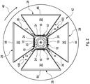
- FIG. 2 shows a schematic of a plurality of combined SPECT-OT detectors on a common gantry, a collimator of a SPECT system being a multi-pinhole type. According to this arrangement, laser scanning and large field light sources are integrated into the inventive apparatus to facilitate fluorescence and bioluminescence imaging.
- four optical detector units 100 are arranged on a common gantry 42, which is rotatable into sense of rotation indicated by arrow 40.
- Four optical detector units 100 each having a SPECT-detector 28, said shielding 26 and a multi-pinhole mask 18 arranged below the optical detectors 10 are provided.
- said optical detector units 100 are arranged within an angle of 90° with respect to one another, thus, completely surrounding said imaged object 22.
- Four light sources A, B, C, D are provided between the respective shielding 26 of two neighboring optical detector units 100 arranged adjacent to one another.
- said second light source B and said first light source A each emit light directed to said imaged object 22 being surrounded by the optical detectors 10.
- said multi-pinhole mask 18 is arranged within the shielding 26 of each of the optical detector units 100.
- Said SPECT-detectors 28 are preferably dual modality detector heads being a part of each optical detector unit 100.
- Each optical detector unit 100 comprises four dual modality heads labeled 44, 46, 48, 50 according to Fig. 2 .
- Each optical detector unit consists of a large-area photo sensor for light detection, a micro lens array for fieldof-view definition, a septum mask for cross-talk suppression, and a transferable filter for wavelength selection.
- optical photons are separated from the photon flux and collimated onto a detector by a cylindrical lattice of micro lens arrays 92 (see Fig. 4 ) (MLAs), which form an inner optical detection ring while a SPECT-detector 28 is mounted in radial extension.
- MLAs micro lens arrays 92
- an optical detector 10 may be mounted onto the surface of the collimator 94 (see Fig. 4 ).
- the inventive apparatus can accommodate the incorporation of different collimators 94, and in that set-up the optical detector 10 may be located most effectively close to the imaged object 22 while the SPECT camera is be positioned further away from the imaged object 22, depending on field-ofview geometry 114.
- multiple cameras can be mounted on a common gantry 42 as illustrated in Fig. 2 and 7 , respectively.
- the four detector heads 44, 46, 48, 50 there also are included, for instance, four light sources, which are necessary for fluorochrome excitation, labeled A to D in Fig. 2 and 7 , respectively.
- sources A and B are bright-field sources
- source C is not producing light
- source D is producing a light beam for focal point illumination.
- Fig. 3 shows the apparatus and results of a study illustrating the improvement of the performance of the SPECT-detector 28 if multi-pinhole collimators 18 are used. Shown are the results for 1, 4, and 6 pinholes with regard to efficiency (sensitivity).
- Said optical detector unit 100 comprises the SPECT-detector 28, the surface of which is labeled by reference numeral 32.
- Said optical detector unit 100 comprises the shielding 26 on top of which the multi-pinhole mask 18 is arranged.
- a distance b shows the distance between the surface of said multi-pinhole mask 18 and the imaged object 22.
- the efficiency is shown with respect to the spatial resolution given in mm.
- a poor third efficiency 80 is achieved by a multi-pinhole mask 18 having one pinhole only.
- An increase in the number of pinholes results in an improvement of efficiency such as the second efficiency 70 when four pinholes are provided in said multi-pinhole mask 18.
- a good first efficiency is obtained, see reference numeral 60, if said multi-pinhole mask 18 comprises six pinholes. The larger the number of pinholes the better the efficiency is. That is the result of the diagram according to Fig. 3 .
- a single optical detector system comprises four parts: (I) a micro lens array 92 intended for field-of-view definition, (2) a large area complementary metal oxide semiconductor (CMOS) chip for light detection, (3) a septum mask for cross-talk suppression, and (4) exchangeable filters 90 for wavelength selection.
- CMOS complementary metal oxide semiconductor
- micro lens arrays 92 also referred to as microlenticular or lens let arrays are used primarily in optical data communication applications, e.g. to interconnect optical fiber bundles, or as light collection elements to increase the optical fill factor in CCDs.
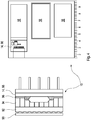
- Fig. 4 shows a rendering of the cross-sectional view of the optical detector 10 along with a photograph of the various parts of the detector 10. See also WO2006111486 .
- said optical detector 10 comprises an exchangeable filter 90, said micro lens array 92, previously being mentioned as well as a collimator 94. Still further, a photosensor 96 and a corresponding electronics 98 are comprised within the optical detector 10. Since all components of said optical detector 10 are very thin, the effective complete detector thickness can be minimized and as previously mentioned amounts to about 4 mm.
- MLAs 92 are produced from fused silica, silicon, or other materials, depending on application wavelength, and are typically available in array sizes up to 120 mm x 120 mm and with lens diameters in the range of 10 microns to 2 mm.
- the MLA 92 is used exclusively for field-of-view definition allowing for non-contact in vivo optical imaging and possibly optical tomography.
- An analogy for illustrating the purpose of the micro lens array in this application might be seen in the use of multi-hole collimators in high-energy detector physics such as in SPECT.
- planar optical projection images should cover an effective area of about 10 cm axially x 5 cm transaxially.
- Tomographic data can potentially be acquired either by rotating a single detector 10 around the object 22 or by mounting a multitude of detectors 10 on a common gantry 42.
- Four detectors 10, as shown in Fig. 2 i.e. reference numerals 44, 46, 48, 50, having the above mentioned dimensions potentially allow for simultaneous tomographic optical imaging.
- Intrinsic spatial resolution 108.1 to 108.8 according to Fig. 5 as a function of object-detector distance d was measured using an electroluminescent light screen (EI-Light, Strausberg, Germany), 10 cm x 10 cm in size, transilluminating a pattern of circles, ranging in diameter from 1.0 mm up to 2.0 mm in 0.2 mm steps, compared in whole diameters 104.0 to 104.5 according to Fig. 5 , similar to the well-known Derenzo-like phantom geometry.
- Detector sensitivity with respect to d was investigated using a red light emitting diode (Kingbright DLA2/6ID, Kingbright Elec. Co., Ltd., Taipei Hsien, Taiwan) powered by a constant current source in the pico-Ampere range.
- a red light emitting diode Kingbright DLA2/6ID, Kingbright Elec. Co., Ltd., Taipei Hsien, Taiwan
- source intensity can be precisely controlled by altering the forward current.
- the maximum forward current applied was 60 pA which yields a light output that is hardly human-perceivable.
- detector sensitivity images were additionally acquired using a highly sensitive CCD camera (Orca-AG, Hamamatsu Photonics K.K., Hamamatsu City, Japan). It employs a cooled advanced progressive scan interline CCD chip with 1344 x 1 024 pixel resolution and is rated at 0.1 electrons per second dark current (at -20 °C), 8 electrons read noise, 18,000 electrons saturation, 12 bits digitization accuracy.
- a 4 x 4 binning was used in all experiments.
- the camera was equipped with a Cinegon 1.4/18 lens (Schneider Optician Werke GmbH, Bad Kreuznach, Germany). Exposure time was set to 30 sec for all measurements, involving the CCD as well as the CMOS sensor.
- Fig. 5 shows the results of a phantom data acquisition study which was performed to asses the imaging characteristics of the optical detector 10 as used in this implementation of dual modality SPECT-OT imaging.
- the distance d between object and detector has been varied between a first detector-object distance 106.1 of 1 cm in 1 cm steps until an object-detector distance of 8 cm, see reference numerals 106.8.
- the steps in between have been made within an 1 cm range, compare reference numerals 106.2, 106.3, 106.4, 106.5, 106.6 and 106.7, respectively.
- reference numerals 106.2, 106.3, 106.4, 106.5, 106.6 and 106.7 respectively.
- intrinsic spatial resolutions 108.1 to 108.8 have been measured.
- the arrangement of pinholes 102 on the multi-pinhole mask 18 according to Fig. 5 has been unaltered, the variation between object and detector has varied.
- the intrinsic spatial resolution 108.8 is more trapezoidal as compared to the very distinct intrinsic spatial resolution 108.1 of the first set-up having a distance 106.1 of 1 cm between detector and object.
- FIG. 6 shows the result of Monte Carlo simulations that have been performed in order to investigate the multi-pinhole setup as well as possible effects the optical sensor might have on the SPECT photons. There were no measurable degradations found as a result of the optical detector 10 being within the field-of-view 114 of the SPECT camera.
- CCD sensors which are two different technologies for capturing images digitally by converting light into electric charge.
- CMOS sensors which are two different technologies for capturing images digitally by converting light into electric charge.
- every pixel's charge is transferred through a single output node, voltage-converted, pre-amplified, buffered, and sent off-chip as an analog signal with comparatively low noise, high dynamic range, and high uniformity.
- CMOS sensors each pixel has its own charge-to-voltage conversion, and most CMOS sensors also include amplifiers, noise-correction, and digitization circuits.
- CMOS sensors have improved considerably in achievable dynamic range and signal-to-noise ratio and start to challenge CCDs in terms of spatial resolution and sensitivity.
- the assembly as presently described employed a Rad-EyeTM1 large-area CMOS imaging sensor (Rad-icon Imaging Corp., Santa Clara, CA).
- CMOS imaging sensor Rad-icon Imaging Corp., Santa Clara, CA.
- Another favorable feature of this sensor is the lateral placement of the read-out electronics 14, 98 which can be placed outside the field-of-view 114 of the SPECT subsystem and such can be shielded to avoid radiation damage.
- the sensor chip is equipped with a 512 x 1024 silicon photodiode matrix at 48 ⁇ m pixel pitch, yielding a 24.6 mm x 49.2 mm active area. These sensors can be positioned head-to-head leaving only a small gap of less than 1mm between sensor fields such that active areas of 10 cm x a manifold of 2.5 cm can be constructed.
- the senor can be operated at frame rates of 0.01 to 4.5 per second and has a dynamic range of 85 dB (14 bits). Average dark current is stated with 4,000 electrons per second (at 23 °C) and the read noise with 150 electrons (at 1 frame per second). Saturation is attained at 2,800,000 electrons per pixel.
- the detector signal is transferred to a PXD1000 digital frame grabber (CyberOptics Semiconductor Inc., Beaverton, OR).
- MLA's 92 size and lens geometry was specified according to the parameters of the CMOS sensor as lens pitch g should be a multiple of pixel pitch, and also with respect to the desired intrinsic spatial resolution (ISR) of the optical imager.
- ISR intrinsic spatial resolution
- MLA lens pitch Given 48 ⁇ m pixel pitch of the CMOS sensor we did chose MLA lens pitch at 480 ⁇ m.
- individual lenses on the MLA correspond to local fields of 10 x 10 sensor pixels.
- the overall size of the MLA is 24.6 mm x 49.2 mm, matching the size of CMOS sensor.
- MLAs were manufactured according to our specifications by Advanced Microoptic Systems GmbH, Saarbruecken, Germany using S-TIH53 optical glass (Ohara Inc., Kanagawa, Japan) of 1mm thickness. Focal lengths of all lenses have been defined at 2.2 mm forming a focal plane at that distance coplanar to the MLA at which the large-field CMOS sensor is aligned.
- the final element of the arrangement is a removable filter 90 located in front of the MLA 92 used to filter the optical signal. In our realization, the filter 90 and its bearing are also used to protect the detector from fluid contamination.
- said shielding 26 of the optical detector unit 100 comprises said SPECT-detector 28 and on its upper sealing the multi-pinhole mask 18 below the optical detector 10.
- the surface 24 of said optical detector 10 is directed towards the imaged object 22.
- said shielding 26 limits the hollow interior 30 of the optical detector unit 100.
- Fig. 6 shows the results of a Monte Carlo simulation 10,000,000 photons, 140.5 keV, rdi lesions: background (1 : 1 : 1): 0 (left hand side)/20 (right hand side).
- a plurality of combined SPECT-OT detectors 28 are arranged on a common gantry 42 which is rotatable in the sense of rotation 40.
- the collimators of this SPECT system each are of fan beam type.
- Laser scanning and large field light sources A, B, C and D, respectively are integrated to provide for fluorescence and bioluminescence imaging.
- Fig. 7 resembles the arrangement according to Fig. 2 , the difference being that said SPECT-detectors 28 having surfaces 32 oriented to the imaged object 22 with shieldings 26.
- Said SPECT-detectors 28 are of fan beam type, the respective field of view indicated by reference numeral 114. Said beams overlap within the area of the imaged object 22 where the optical detectors 10 between which said light sources A, B, C and D, respectively, are arranged.
Landscapes
- Health & Medical Sciences (AREA)
- Life Sciences & Earth Sciences (AREA)
- Physics & Mathematics (AREA)
- Engineering & Computer Science (AREA)
- Medical Informatics (AREA)
- Molecular Biology (AREA)
- Nuclear Medicine, Radiotherapy & Molecular Imaging (AREA)
- General Health & Medical Sciences (AREA)
- High Energy & Nuclear Physics (AREA)
- Biomedical Technology (AREA)
- Radiology & Medical Imaging (AREA)
- Pathology (AREA)
- Heart & Thoracic Surgery (AREA)
- Surgery (AREA)
- Animal Behavior & Ethology (AREA)
- Biophysics (AREA)
- Public Health (AREA)
- Veterinary Medicine (AREA)
- Optics & Photonics (AREA)
- General Physics & Mathematics (AREA)
- Spectroscopy & Molecular Physics (AREA)
- Investigating, Analyzing Materials By Fluorescence Or Luminescence (AREA)
- Nuclear Medicine (AREA)
Claims (9)
- Système d'imagerie à deux modalités, dans lequel au moins une caméra de tomographie d'émission à photon unique (SPECT) destinée à acquérir des données de tomographie SPECT, et au moins un détecteur d'imagerie optique (10) destiné à acquérir des données d'imagerie optique, sont agencés de manière à acquérir les données de tomographie SPECT et les données d'imagerie optique d'un objet imagé (22) simultanément, et à partir du même angle de projection, ledit au moins un détecteur d'imagerie optique (10) étant un détecteur d'imagerie optique sans contact pour l'imagerie de bioluminescence, de fluorescence et de réflectance, et dans lequel l'appareil de sous-système de tomographie SPECT comprend un détecteur de tomographie SPECT (28) auquel un collimateur (18) est fixé en vue d'une imagerie isotopique à haute résolution / haute sensibilité, et dans lequel au moins un détecteur d'imagerie optique (10) est agencé au sein du volume d'imagerie en vue de détecter les photons émis par l'objet imagé (22), caractérisé en ce que ledit au moins un détecteur d'imagerie optique (10) comprend un réseau de microlentilles (92) avec une pluralité de microlentilles, le détecteur optique (10) étant fixé sur la surface du collimateur (18) du système de tomographie SPECT.
- Système d'imagerie à deux modalités selon la revendication 1, dans lequel le collimateur de l'appareil de sous-système de tomographie SPECT est un collimateur de type à trou unique, ou est un collimateur de type à trous multiples (18), ou est un collimateur de type à faisceau parallèle, ou est un collimateur de type à faisceau en éventail, ou est un collimateur de type à faisceau conique, ou est un collimateur de type astigmatique, ou est l'un quelconque parmi un collimateur de type à trous multiples parallèle, divergent ou convergent, ou est un collimateur de type convergent avec un(e) unique ligne ou point focal, ou une multitude de points focaux ou lignes.
- Système d'imagerie à deux modalités selon la revendication 1, dans lequel ledit au moins un détecteur d'imagerie optique (10) comprend au moins un photodétecteur.
- Système d'imagerie à deux modalités selon la revendication 1, dans lequel ledit au moins un détecteur d'imagerie optique (10) comprend un photodétecteur sensible à la position.
- Système d'imagerie à deux modalités selon la revendication 4, dans lequel le photodétecteur sensible à la position est positionné dans le plan focal d'un réseau de microlentilles (92).
- Système d'imagerie à deux modalités selon la revendication 4, dans lequel le photodétecteur sensible à la position est au moins un capteur (96) sélectionné à partir du groupe constitué par un détecteur à base de dispositif à couplage de charge (CCD), un réseau de photodiodes à avalanche (APD), un réseau de photodiodes, ou un capteur à semi-conducteur à oxyde de métal complémentaire (CMOS).
- Système d'imagerie à deux modalités selon la revendication 1, dans lequel au moins une combinaison du détecteur de tomographie SPECT (28) et du détecteur d'imagerie optique (10) est montée sur un portique commun (42) pouvant effectuer une rotation de 360 degrés en vue de permettre un positionnement radial arbitraire du ou des détecteurs optiques (10) et de la ou des caméras de tomographie SPECT (28) et de permettre l'imagerie tomographique.
- Système d'imagerie à deux modalités selon la revendication 1, comprenant en outre une unique ou une pluralité de sources de lumière (A, B, C, D) pour éclairer l'objet imagé (22).
- Système d'imagerie à deux modalités selon la revendication 1, dans lequel le collimateur est un collimateur de type à trous multiples (18).
Applications Claiming Priority (2)
| Application Number | Priority Date | Filing Date | Title |
|---|---|---|---|
| US96073107P | 2007-10-11 | 2007-10-11 | |
| PCT/EP2008/063617 WO2009047328A2 (fr) | 2007-10-11 | 2008-10-10 | Association de détecteur à tomographie d'émission monophotonique et d'imagerie optique |
Publications (2)
| Publication Number | Publication Date |
|---|---|
| EP2201408A2 EP2201408A2 (fr) | 2010-06-30 |
| EP2201408B1 true EP2201408B1 (fr) | 2016-12-07 |
Family
ID=40549646
Family Applications (1)
| Application Number | Title | Priority Date | Filing Date |
|---|---|---|---|
| EP08837353.5A Not-in-force EP2201408B1 (fr) | 2007-10-11 | 2008-10-10 | Association de detecteur a tomographie d'emission monophotonique et d'imagerie optique |
Country Status (3)
| Country | Link |
|---|---|
| US (1) | US8653464B2 (fr) |
| EP (1) | EP2201408B1 (fr) |
| WO (1) | WO2009047328A2 (fr) |
Families Citing this family (11)
| Publication number | Priority date | Publication date | Assignee | Title |
|---|---|---|---|---|
| ES2346623B1 (es) * | 2009-01-07 | 2011-10-03 | Consejo Superior De Investigaciones Científicas (Csic) | Sistema compacto, hibrido e integrado gamma/rf para la formacion de imagenes simultaneas petspect/mr. |
| CN103260521B (zh) * | 2010-12-14 | 2015-11-25 | 皇家飞利浦电子股份有限公司 | 用于准确的输入函数估计的整合的工作流程 |
| WO2013112709A1 (fr) * | 2012-01-24 | 2013-08-01 | Niedre Mark | Systèmes et procédés de détection, d'énumération et d'imagerie de cellules rares avec une lumière diffuse |
| EP2823334B1 (fr) | 2012-08-30 | 2016-03-23 | Mediso Orvosi Berendezés Fejlesztö És Szerviz Kft. | Appareil d'imagerie, ouverture pour l'appareil d'imagerie et procédé de fabrication d'une ouverture d'appareil d'imagerie |
| US20140152804A1 (en) * | 2012-12-05 | 2014-06-05 | Seagate Technology Llc | Sub-pixel imaging for enhanced pixel resolution |
| US9442197B2 (en) * | 2014-09-15 | 2016-09-13 | General Electric Company | Method and systems for a swiveling detector head |
| WO2017197165A1 (fr) * | 2016-05-12 | 2017-11-16 | The Board Of Trustees Of The Leland Stanford Junior University | Sonde de détection de l'athérosclérose |
| WO2018015437A1 (fr) * | 2016-07-19 | 2018-01-25 | Universität Basel | Dispositif d'imagerie et procédé de visualisation d'un ganglion lymphatique sentinelle |
| US10942282B2 (en) | 2016-09-13 | 2021-03-09 | Koninklijke Philips N.V. | Combined imaging detector for x-ray and nuclear imaging |
| HUP1600577A2 (en) | 2016-10-14 | 2018-06-28 | Mediso Medical Imaging Systems Kft | Imaging device with tomography apparatus |
| GB201806436D0 (en) * | 2018-04-20 | 2018-06-06 | Cavendish Nuclear Ltd | Improvements in and relating to detection |
Family Cites Families (5)
| Publication number | Priority date | Publication date | Assignee | Title |
|---|---|---|---|---|
| DE10225932B4 (de) * | 2002-06-11 | 2007-01-11 | Deutsches Krebsforschungszentrum (Dkfz) | Bildgebendes Verfahren und Vorrichtung zu dessen Durchführung |
| US7265356B2 (en) * | 2004-11-29 | 2007-09-04 | The University Of Chicago | Image-guided medical intervention apparatus and method |
| US20060239398A1 (en) * | 2005-03-07 | 2006-10-26 | Fused Multimodality Imaging, Ltd. | Breast diagnostic apparatus for fused SPECT, PET, x-ray CT, and optical surface imaging of breast cancer |
| EP1715361B1 (fr) | 2005-04-19 | 2015-02-25 | Deutsches Krebsforschungszentrum Stiftung des öffentlichen Rechts | Imagerie avec deux modes utilisant un tomographe par émission de positons et un détecteur optique |
| DE102005037900A1 (de) * | 2005-08-10 | 2007-02-15 | Siemens Ag | Kollimator und Detektoranordnung mit einem derartigen Kollimator |
-
2008
- 2008-10-10 EP EP08837353.5A patent/EP2201408B1/fr not_active Not-in-force
- 2008-10-10 WO PCT/EP2008/063617 patent/WO2009047328A2/fr not_active Ceased
- 2008-10-10 US US12/681,839 patent/US8653464B2/en not_active Expired - Fee Related
Also Published As
| Publication number | Publication date |
|---|---|
| WO2009047328A3 (fr) | 2009-10-15 |
| US20100219348A1 (en) | 2010-09-02 |
| US8653464B2 (en) | 2014-02-18 |
| EP2201408A2 (fr) | 2010-06-30 |
| WO2009047328A2 (fr) | 2009-04-16 |
Similar Documents
| Publication | Publication Date | Title |
|---|---|---|
| EP2201408B1 (fr) | Association de detecteur a tomographie d'emission monophotonique et d'imagerie optique | |
| US8227754B2 (en) | Optical imaging detector | |
| US20100030069A1 (en) | Triple-modality imaging system | |
| Levin | Primer on molecular imaging technology | |
| Prout et al. | Detector concept for OPET-A combined PET and optical imaging system | |
| WO2020168205A1 (fr) | Détecteur de tomographie par emission de positrons (pet) à codage de profondeur à haute résolution ayant un réseau de guides de lumière prismatoïdes | |
| JP2009534661A (ja) | マイクロ流体プラットフォームのラジオアイソトープ濃度数量化デバイス | |
| EP1523337B1 (fr) | Procede d'imagerie et dispositif pour son execution | |
| WO2014193066A1 (fr) | Détecteur de tomographie par émission de positons et système de tomographie par émission de positons l'utilisant | |
| EP1698911B1 (fr) | Detecteur de rayonnement | |
| US8183530B2 (en) | Positron emission tomography and optical tissue imaging | |
| Braem et al. | Novel design of a parallax free Compton enhanced PET scanner | |
| US10234573B2 (en) | Digital probe | |
| Azman et al. | A nuclear radiation detector system with integrated readout for SPECT/MR small animal imaging | |
| Fiorini et al. | The DRAGO gamma camera | |
| Mendes et al. | Evaluation of monolithic detector blocks for high-sensitivity PET imaging of the human brain | |
| Peter et al. | A novel optical detector concept for dedicated and multi-modality in vivo small animal imaging | |
| Peter | Dual-Modality Preclinical PET-OI Concepts and Instrumentation |
Legal Events
| Date | Code | Title | Description |
|---|---|---|---|
| PUAI | Public reference made under article 153(3) epc to a published international application that has entered the european phase |
Free format text: ORIGINAL CODE: 0009012 |
|
| 17P | Request for examination filed |
Effective date: 20100426 |
|
| AK | Designated contracting states |
Kind code of ref document: A2 Designated state(s): AT BE BG CH CY CZ DE DK EE ES FI FR GB GR HR HU IE IS IT LI LT LU LV MC MT NL NO PL PT RO SE SI SK TR |
|
| AX | Request for extension of the european patent |
Extension state: AL BA MK RS |
|
| DAX | Request for extension of the european patent (deleted) | ||
| 17Q | First examination report despatched |
Effective date: 20141113 |
|
| GRAP | Despatch of communication of intention to grant a patent |
Free format text: ORIGINAL CODE: EPIDOSNIGR1 |
|
| INTG | Intention to grant announced |
Effective date: 20160524 |
|
| GRAS | Grant fee paid |
Free format text: ORIGINAL CODE: EPIDOSNIGR3 |
|
| GRAA | (expected) grant |
Free format text: ORIGINAL CODE: 0009210 |
|
| STAA | Information on the status of an ep patent application or granted ep patent |
Free format text: STATUS: THE PATENT HAS BEEN GRANTED |
|
| AK | Designated contracting states |
Kind code of ref document: B1 Designated state(s): AT BE BG CH CY CZ DE DK EE ES FI FR GB GR HR HU IE IS IT LI LT LU LV MC MT NL NO PL PT RO SE SI SK TR |
|
| REG | Reference to a national code |
Ref country code: GB Ref legal event code: FG4D |
|
| REG | Reference to a national code |
Ref country code: CH Ref legal event code: EP Ref country code: AT Ref legal event code: REF Ref document number: 852224 Country of ref document: AT Kind code of ref document: T Effective date: 20161215 |
|
| REG | Reference to a national code |
Ref country code: IE Ref legal event code: FG4D |
|
| REG | Reference to a national code |
Ref country code: DE Ref legal event code: R096 Ref document number: 602008047787 Country of ref document: DE |
|
| PG25 | Lapsed in a contracting state [announced via postgrant information from national office to epo] |
Ref country code: LV Free format text: LAPSE BECAUSE OF FAILURE TO SUBMIT A TRANSLATION OF THE DESCRIPTION OR TO PAY THE FEE WITHIN THE PRESCRIBED TIME-LIMIT Effective date: 20161207 |
|
| REG | Reference to a national code |
Ref country code: LT Ref legal event code: MG4D |
|
| REG | Reference to a national code |
Ref country code: NL Ref legal event code: MP Effective date: 20161207 |
|
| PG25 | Lapsed in a contracting state [announced via postgrant information from national office to epo] |
Ref country code: LT Free format text: LAPSE BECAUSE OF FAILURE TO SUBMIT A TRANSLATION OF THE DESCRIPTION OR TO PAY THE FEE WITHIN THE PRESCRIBED TIME-LIMIT Effective date: 20161207 Ref country code: SE Free format text: LAPSE BECAUSE OF FAILURE TO SUBMIT A TRANSLATION OF THE DESCRIPTION OR TO PAY THE FEE WITHIN THE PRESCRIBED TIME-LIMIT Effective date: 20161207 Ref country code: NO Free format text: LAPSE BECAUSE OF FAILURE TO SUBMIT A TRANSLATION OF THE DESCRIPTION OR TO PAY THE FEE WITHIN THE PRESCRIBED TIME-LIMIT Effective date: 20170307 Ref country code: GR Free format text: LAPSE BECAUSE OF FAILURE TO SUBMIT A TRANSLATION OF THE DESCRIPTION OR TO PAY THE FEE WITHIN THE PRESCRIBED TIME-LIMIT Effective date: 20170308 |
|
| REG | Reference to a national code |
Ref country code: AT Ref legal event code: MK05 Ref document number: 852224 Country of ref document: AT Kind code of ref document: T Effective date: 20161207 |
|
| PG25 | Lapsed in a contracting state [announced via postgrant information from national office to epo] |
Ref country code: HR Free format text: LAPSE BECAUSE OF FAILURE TO SUBMIT A TRANSLATION OF THE DESCRIPTION OR TO PAY THE FEE WITHIN THE PRESCRIBED TIME-LIMIT Effective date: 20161207 Ref country code: FI Free format text: LAPSE BECAUSE OF FAILURE TO SUBMIT A TRANSLATION OF THE DESCRIPTION OR TO PAY THE FEE WITHIN THE PRESCRIBED TIME-LIMIT Effective date: 20161207 Ref country code: ES Free format text: LAPSE BECAUSE OF FAILURE TO SUBMIT A TRANSLATION OF THE DESCRIPTION OR TO PAY THE FEE WITHIN THE PRESCRIBED TIME-LIMIT Effective date: 20161207 |
|
| PG25 | Lapsed in a contracting state [announced via postgrant information from national office to epo] |
Ref country code: NL Free format text: LAPSE BECAUSE OF FAILURE TO SUBMIT A TRANSLATION OF THE DESCRIPTION OR TO PAY THE FEE WITHIN THE PRESCRIBED TIME-LIMIT Effective date: 20161207 |
|
| PG25 | Lapsed in a contracting state [announced via postgrant information from national office to epo] |
Ref country code: IS Free format text: LAPSE BECAUSE OF FAILURE TO SUBMIT A TRANSLATION OF THE DESCRIPTION OR TO PAY THE FEE WITHIN THE PRESCRIBED TIME-LIMIT Effective date: 20170407 Ref country code: RO Free format text: LAPSE BECAUSE OF FAILURE TO SUBMIT A TRANSLATION OF THE DESCRIPTION OR TO PAY THE FEE WITHIN THE PRESCRIBED TIME-LIMIT Effective date: 20161207 Ref country code: CZ Free format text: LAPSE BECAUSE OF FAILURE TO SUBMIT A TRANSLATION OF THE DESCRIPTION OR TO PAY THE FEE WITHIN THE PRESCRIBED TIME-LIMIT Effective date: 20161207 Ref country code: SK Free format text: LAPSE BECAUSE OF FAILURE TO SUBMIT A TRANSLATION OF THE DESCRIPTION OR TO PAY THE FEE WITHIN THE PRESCRIBED TIME-LIMIT Effective date: 20161207 Ref country code: EE Free format text: LAPSE BECAUSE OF FAILURE TO SUBMIT A TRANSLATION OF THE DESCRIPTION OR TO PAY THE FEE WITHIN THE PRESCRIBED TIME-LIMIT Effective date: 20161207 |
|
| PG25 | Lapsed in a contracting state [announced via postgrant information from national office to epo] |
Ref country code: BE Free format text: LAPSE BECAUSE OF FAILURE TO SUBMIT A TRANSLATION OF THE DESCRIPTION OR TO PAY THE FEE WITHIN THE PRESCRIBED TIME-LIMIT Effective date: 20161207 Ref country code: PT Free format text: LAPSE BECAUSE OF FAILURE TO SUBMIT A TRANSLATION OF THE DESCRIPTION OR TO PAY THE FEE WITHIN THE PRESCRIBED TIME-LIMIT Effective date: 20170407 Ref country code: IT Free format text: LAPSE BECAUSE OF FAILURE TO SUBMIT A TRANSLATION OF THE DESCRIPTION OR TO PAY THE FEE WITHIN THE PRESCRIBED TIME-LIMIT Effective date: 20161207 Ref country code: BG Free format text: LAPSE BECAUSE OF FAILURE TO SUBMIT A TRANSLATION OF THE DESCRIPTION OR TO PAY THE FEE WITHIN THE PRESCRIBED TIME-LIMIT Effective date: 20170307 Ref country code: AT Free format text: LAPSE BECAUSE OF FAILURE TO SUBMIT A TRANSLATION OF THE DESCRIPTION OR TO PAY THE FEE WITHIN THE PRESCRIBED TIME-LIMIT Effective date: 20161207 Ref country code: PL Free format text: LAPSE BECAUSE OF FAILURE TO SUBMIT A TRANSLATION OF THE DESCRIPTION OR TO PAY THE FEE WITHIN THE PRESCRIBED TIME-LIMIT Effective date: 20161207 |
|
| REG | Reference to a national code |
Ref country code: DE Ref legal event code: R097 Ref document number: 602008047787 Country of ref document: DE |
|
| PLBE | No opposition filed within time limit |
Free format text: ORIGINAL CODE: 0009261 |
|
| STAA | Information on the status of an ep patent application or granted ep patent |
Free format text: STATUS: NO OPPOSITION FILED WITHIN TIME LIMIT |
|
| REG | Reference to a national code |
Ref country code: FR Ref legal event code: PLFP Year of fee payment: 10 |
|
| 26N | No opposition filed |
Effective date: 20170908 |
|
| PG25 | Lapsed in a contracting state [announced via postgrant information from national office to epo] |
Ref country code: SI Free format text: LAPSE BECAUSE OF FAILURE TO SUBMIT A TRANSLATION OF THE DESCRIPTION OR TO PAY THE FEE WITHIN THE PRESCRIBED TIME-LIMIT Effective date: 20161207 Ref country code: DK Free format text: LAPSE BECAUSE OF FAILURE TO SUBMIT A TRANSLATION OF THE DESCRIPTION OR TO PAY THE FEE WITHIN THE PRESCRIBED TIME-LIMIT Effective date: 20161207 |
|
| PGFP | Annual fee paid to national office [announced via postgrant information from national office to epo] |
Ref country code: FR Payment date: 20171023 Year of fee payment: 10 Ref country code: DE Payment date: 20171023 Year of fee payment: 10 |
|
| PGFP | Annual fee paid to national office [announced via postgrant information from national office to epo] |
Ref country code: GB Payment date: 20171024 Year of fee payment: 10 |
|
| PG25 | Lapsed in a contracting state [announced via postgrant information from national office to epo] |
Ref country code: MC Free format text: LAPSE BECAUSE OF FAILURE TO SUBMIT A TRANSLATION OF THE DESCRIPTION OR TO PAY THE FEE WITHIN THE PRESCRIBED TIME-LIMIT Effective date: 20161207 |
|
| REG | Reference to a national code |
Ref country code: CH Ref legal event code: PL |
|
| REG | Reference to a national code |
Ref country code: IE Ref legal event code: MM4A |
|
| PG25 | Lapsed in a contracting state [announced via postgrant information from national office to epo] |
Ref country code: CH Free format text: LAPSE BECAUSE OF NON-PAYMENT OF DUE FEES Effective date: 20171031 Ref country code: LI Free format text: LAPSE BECAUSE OF NON-PAYMENT OF DUE FEES Effective date: 20171031 Ref country code: LU Free format text: LAPSE BECAUSE OF NON-PAYMENT OF DUE FEES Effective date: 20171010 |
|
| PG25 | Lapsed in a contracting state [announced via postgrant information from national office to epo] |
Ref country code: MT Free format text: LAPSE BECAUSE OF NON-PAYMENT OF DUE FEES Effective date: 20171010 |
|
| PG25 | Lapsed in a contracting state [announced via postgrant information from national office to epo] |
Ref country code: IE Free format text: LAPSE BECAUSE OF NON-PAYMENT OF DUE FEES Effective date: 20171010 |
|
| REG | Reference to a national code |
Ref country code: DE Ref legal event code: R119 Ref document number: 602008047787 Country of ref document: DE |
|
| GBPC | Gb: european patent ceased through non-payment of renewal fee |
Effective date: 20181010 |
|
| PG25 | Lapsed in a contracting state [announced via postgrant information from national office to epo] |
Ref country code: HU Free format text: LAPSE BECAUSE OF FAILURE TO SUBMIT A TRANSLATION OF THE DESCRIPTION OR TO PAY THE FEE WITHIN THE PRESCRIBED TIME-LIMIT; INVALID AB INITIO Effective date: 20081010 |
|
| PG25 | Lapsed in a contracting state [announced via postgrant information from national office to epo] |
Ref country code: DE Free format text: LAPSE BECAUSE OF NON-PAYMENT OF DUE FEES Effective date: 20190501 |
|
| PG25 | Lapsed in a contracting state [announced via postgrant information from national office to epo] |
Ref country code: FR Free format text: LAPSE BECAUSE OF NON-PAYMENT OF DUE FEES Effective date: 20181031 |
|
| PG25 | Lapsed in a contracting state [announced via postgrant information from national office to epo] |
Ref country code: CY Free format text: LAPSE BECAUSE OF NON-PAYMENT OF DUE FEES Effective date: 20161207 Ref country code: GB Free format text: LAPSE BECAUSE OF NON-PAYMENT OF DUE FEES Effective date: 20181010 |
|
| PG25 | Lapsed in a contracting state [announced via postgrant information from national office to epo] |
Ref country code: TR Free format text: LAPSE BECAUSE OF FAILURE TO SUBMIT A TRANSLATION OF THE DESCRIPTION OR TO PAY THE FEE WITHIN THE PRESCRIBED TIME-LIMIT Effective date: 20161207 |