EP2201535B1 - Locking device - Google Patents
Locking device Download PDFInfo
- Publication number
- EP2201535B1 EP2201535B1 EP08800434A EP08800434A EP2201535B1 EP 2201535 B1 EP2201535 B1 EP 2201535B1 EP 08800434 A EP08800434 A EP 08800434A EP 08800434 A EP08800434 A EP 08800434A EP 2201535 B1 EP2201535 B1 EP 2201535B1
- Authority
- EP
- European Patent Office
- Prior art keywords
- locking device
- locking
- lock
- coupling
- coupling condition
- Prior art date
- Legal status (The legal status is an assumption and is not a legal conclusion. Google has not performed a legal analysis and makes no representation as to the accuracy of the status listed.)
- Active
Links
Images


Classifications
-
- E—FIXED CONSTRUCTIONS
- E05—LOCKS; KEYS; WINDOW OR DOOR FITTINGS; SAFES
- E05B—LOCKS; ACCESSORIES THEREFOR; HANDCUFFS
- E05B67/00—Padlocks; Details thereof
- E05B67/02—Cases
-
- E—FIXED CONSTRUCTIONS
- E05—LOCKS; KEYS; WINDOW OR DOOR FITTINGS; SAFES
- E05B—LOCKS; ACCESSORIES THEREFOR; HANDCUFFS
- E05B47/00—Operating or controlling locks or other fastening devices by electric or magnetic means
- E05B47/0001—Operating or controlling locks or other fastening devices by electric or magnetic means with electric actuators; Constructional features thereof
- E05B47/0012—Operating or controlling locks or other fastening devices by electric or magnetic means with electric actuators; Constructional features thereof with rotary electromotors
-
- E—FIXED CONSTRUCTIONS
- E05—LOCKS; KEYS; WINDOW OR DOOR FITTINGS; SAFES
- E05B—LOCKS; ACCESSORIES THEREFOR; HANDCUFFS
- E05B47/00—Operating or controlling locks or other fastening devices by electric or magnetic means
- E05B47/06—Controlling mechanically-operated bolts by electro-magnetically-operated detents
- E05B47/0603—Controlling mechanically-operated bolts by electro-magnetically-operated detents the detent moving rectilinearly
-
- G—PHYSICS
- G07—CHECKING-DEVICES
- G07C—TIME OR ATTENDANCE REGISTERS; REGISTERING OR INDICATING THE WORKING OF MACHINES; GENERATING RANDOM NUMBERS; VOTING OR LOTTERY APPARATUS; ARRANGEMENTS, SYSTEMS OR APPARATUS FOR CHECKING NOT PROVIDED FOR ELSEWHERE
- G07C9/00—Individual registration on entry or exit
- G07C9/00174—Electronically operated locks; Circuits therefor; Nonmechanical keys therefor, e.g. passive or active electrical keys or other data carriers without mechanical keys
- G07C9/00309—Electronically operated locks; Circuits therefor; Nonmechanical keys therefor, e.g. passive or active electrical keys or other data carriers without mechanical keys operated with bidirectional data transmission between data carrier and locks
-
- E—FIXED CONSTRUCTIONS
- E05—LOCKS; KEYS; WINDOW OR DOOR FITTINGS; SAFES
- E05B—LOCKS; ACCESSORIES THEREFOR; HANDCUFFS
- E05B17/00—Accessories in connection with locks
- E05B17/04—Devices for coupling the turning cylinder of a single or a double cylinder lock with the bolt operating member
- E05B17/042—Devices for coupling the turning cylinder of a single or a double cylinder lock with the bolt operating member using toothed wheels or geared sectors
- E05B2017/043—Planetary gear
-
- E—FIXED CONSTRUCTIONS
- E05—LOCKS; KEYS; WINDOW OR DOOR FITTINGS; SAFES
- E05B—LOCKS; ACCESSORIES THEREFOR; HANDCUFFS
- E05B47/00—Operating or controlling locks or other fastening devices by electric or magnetic means
- E05B2047/0048—Circuits, feeding, monitoring
- E05B2047/0057—Feeding
- E05B2047/0062—Feeding by generator
-
- E—FIXED CONSTRUCTIONS
- E05—LOCKS; KEYS; WINDOW OR DOOR FITTINGS; SAFES
- E05B—LOCKS; ACCESSORIES THEREFOR; HANDCUFFS
- E05B47/00—Operating or controlling locks or other fastening devices by electric or magnetic means
- E05B2047/0048—Circuits, feeding, monitoring
- E05B2047/0057—Feeding
- E05B2047/0063—Energy transfer from key to lock, e.g. for emergency opening
-
- G—PHYSICS
- G07—CHECKING-DEVICES
- G07C—TIME OR ATTENDANCE REGISTERS; REGISTERING OR INDICATING THE WORKING OF MACHINES; GENERATING RANDOM NUMBERS; VOTING OR LOTTERY APPARATUS; ARRANGEMENTS, SYSTEMS OR APPARATUS FOR CHECKING NOT PROVIDED FOR ELSEWHERE
- G07C9/00—Individual registration on entry or exit
- G07C9/00174—Electronically operated locks; Circuits therefor; Nonmechanical keys therefor, e.g. passive or active electrical keys or other data carriers without mechanical keys
- G07C2009/00634—Power supply for the lock
-
- G—PHYSICS
- G07—CHECKING-DEVICES
- G07C—TIME OR ATTENDANCE REGISTERS; REGISTERING OR INDICATING THE WORKING OF MACHINES; GENERATING RANDOM NUMBERS; VOTING OR LOTTERY APPARATUS; ARRANGEMENTS, SYSTEMS OR APPARATUS FOR CHECKING NOT PROVIDED FOR ELSEWHERE
- G07C9/00—Individual registration on entry or exit
- G07C9/00174—Electronically operated locks; Circuits therefor; Nonmechanical keys therefor, e.g. passive or active electrical keys or other data carriers without mechanical keys
- G07C2009/00753—Electronically operated locks; Circuits therefor; Nonmechanical keys therefor, e.g. passive or active electrical keys or other data carriers without mechanical keys operated by active electrical keys
- G07C2009/00769—Electronically operated locks; Circuits therefor; Nonmechanical keys therefor, e.g. passive or active electrical keys or other data carriers without mechanical keys operated by active electrical keys with data transmission performed by wireless means
- G07C2009/00793—Electronically operated locks; Circuits therefor; Nonmechanical keys therefor, e.g. passive or active electrical keys or other data carriers without mechanical keys operated by active electrical keys with data transmission performed by wireless means by Hertzian waves
Definitions
- the invention relates to a locking device for locks, for example. Padlocks.
- Locking devices with electronically controlled actuatable locking elements - mechatronic locking devices - are known.
- the electronically controlled locking is based on a data transmission between a key-side electronic module and a lock-side electronic module. This data transmission can take place by contact - for example by means of electrical contacts on key and lock - or without contact - for example via radio frequency transmission. Data can be transmitted in one or both directions.
- At least the lock-side unit of the locking device generally requires a power supply (own battery, contact to key side battery, mains connection), on the one hand for operating the electronic module, on the other hand for actuating the blocking elements.
- the energy supply of the key-side electronic module can be made from the lock-side unit, for example in the case of RFID technology.
- This dual function of the stepping motor is advantageous for a combination lock, but it is not transferable to other applications.
- the locking device has as known per se an electronic module for receiving data from an identification unit (such may be formed as a card, eg. Chip card or other form and possibly even perform additional functions) and an electric motor for actuating a blocking and / or Coupling device for the lock, wherein the motor can be controlled by the electronic module.
- the locking device is characterized by the fact that it can be brought into a first and a second coupling state, wherein in the first coupling state, the motor is coupled to an actuating element and acts upon actuation of the actuating element as a generator. In a second coupling state, the motor is coupled to the locking and / or coupling device and can unlock the lock by actuating it.
- a lock (as a reverse operation of the unlocking) of the lock can also be effected by the motor, and / or it can be provided that by suitable spring means, etc., the locking device automatically gets into the locked state under the right conditions.
- the inventive method allows autonomous, independent of external power supply and batteries solution even in confined spaces, eg. In a padlock.
- the actuator is accessible from outside the lock and can be designed as a handle, for example. As a knob, - possibly folding - crank element, etc.
- the actuator may also be formed in the manner of a lock cylinder rotor and actuated only by an inserted mechanical key.
- a mechanical key can have coding holes in a manner known per se, which cooperate with tumbler counter pairs of the actuating element, whereby the actuating element can be actuated only when the key is in place (and the energy stores of the electronic module are rechargeable).
- actuating actuator - eg. By rotation through 90 ° or 180 ° - takes place. Then, the correct mechanical coding can also be a prerequisite for the actuation element to be actuatable in the second coupling state.
- Such a mechanical key may be provided simultaneously with the identification unit which transmits data to the electronic module; then he may be externally similar trained as already known key of mechanical mechatronic locks. Such keys have often incorporated an electronic module in the handle.
- a transmission between the actuating element and the motor, by means of which a (rotary) movement which can be generated by the actuating element is translated.
- Suitable gear is a planetary gear, since all gear elements can be arranged in a plane and the driven to be connected to the shaft of the motor gear can be centrally.
- other transmissions for example spur gears, are also suitable.
- the transmission may be integrated in an engine block or at least partially formed as a separate element (eg. As part of a transmission module).
- the actuating element is to be moved in translation and that suitable transmission means deflect this translatory movement into a rotational movement.
- the coupling between the actuating element and the motor can optionally be set up so that the transmittable force is limited, that is to say between the actuating element and the motor (possibly together with a gear) a spring element, a sliding clutch or a comparable means can be present the effect is that excessive force on the actuator, the force acting on the motor is damped.
- the locking and / or coupling device has at least two locking mechanism stages.
- the lock With a second locking mechanism, the lock itself is lockable.
- the second lock mechanism blocks the padlock against the housing.
- the lock is a cylinder lock, locks the second locking mechanism, the rotor of the cylinder and / or an output member and / or a locking element relative to the housing.
- the first locking mechanism stage is according to this particular embodiment, a manually operable intermediate element with respect to the housing lockable, or (according to the above option b.) Coupled with another element.
- the first lock mechanism stage is actuated by the motor, the second Locking mechanism stage through the intermediate element, ie the unlocking on the first locking mechanism stage is a prerequisite that can be unlocked on the second locking mechanism stage.
- the first and second clutch states may be different in that a shaft of the engine is in operative connection with the transmission means in the first clutch state and in the second state with a control mechanism which effects a lock and / or a clutch.
- Such a control mechanism may, for example, have a control which has a control surface and thereby influences the position and / or the movement (free) space of blocking elements during a rotation or other movement.
- This is particularly favorable in a cylindrical arrangement, but can be implemented by such a control surface a rotational movement in the simplest way in a radial movement.
- locking elements can be pressed by a spring force radially inwardly against the control surface and move radially upon rotation of the control accordingly due to the spring force or against the spring force, thereby releasing or blocking a shear surface depending on the situation.
- such a control preferably belongs to the first lock mechanism stage.
- a control can also cause a locking element itself to be displaced, for example by using the lifting spindle principle.
- the locking device is of modular construction and - possibly with minor modifications - suitable for different lock types. It can have a cylindrical shape as a whole. Alternatively, it may also have another, for example, standard (eg, Hahn profile (DIN 18252, also called Europrofil) or similar profile.) In such a case, the locking device has a lot with the corresponding profile cylinder cross-section, the actuating element projecting from this lot and can have a bigger cross-section - and in general too.
- standard eg, Hahn profile (DIN 18252, also called Europrofil
- the locking device has a lot with the corresponding profile cylinder cross-section, the actuating element projecting from this lot and can have a bigger cross-section - and in general too.
- a module comprising the electric motor may further comprise an externally hermetically sealed housing which is interrupted only by an opening for the outwardly projecting shaft, this opening being sealed.
- the housing may be partially metallic, but preferably comprises a non-metallic component in the case of contactless information transmission, so that an antenna mounted inside the housing can receive electromagnetic signals from outside.
- the housing may also be non-metallic as a whole, for example. Plastic.
- the locking device may also have a purely mechanical coding, so that additionally a key provided with mechanical codings has to be used in order to actuate the lock. Such a key may additionally include the identification unit.
- the identification ie the transmission of data from the identification unit to the electronic module and possibly also from the electronic module to the identification unit
- the identification takes place without contact, for example with RFID technology.
- the information transfer by means of Capacitive-resistive coupling by the user, as in the Scriptures WO 2007/036 06 , the international patent application PCT / CH 2007/000166 or references cited therein.
- Other contactless or kotnaktbehaftete information transmission types for example. About IR, electromagnetic fields of other frequencies, acoustically (ultrasound), etc. are possible.
- the identification unit is to be worn only on the body, for example in the trouser pocket. The user then only has to operate the generator by bringing the locking device in the first coupling state and moves the actuator as intended. While the user is doing this or immediately thereafter, an information transfer (via electromagnetic waves and / or capacitive / resistive via the user's body can take place immediately, so that the lock can be opened immediately after the energy storage medium has been charged.
- the device automatically transitions from the first to the second coupling state, for example by a spring force.
- a first important application of locking devices according to the invention are, as mentioned, padlocks to which more and more security requirements are being made, as well as for more complex locking systems.
- padlocks are often used to protect the infrastructure of mobile operators, etc. in remote locations. Such infrastructure may only be maintained sporadically, and it is therefore important to ensure proper functioning even if the lock has not been operated for a long time.
- the device according to the invention can also be used in connection with lock cylinders which are not readily supplied with electricity, for example in connection with lock cylinders (this term also includes 'half cylinders', ie lock cylinders which can only be actuated on one side) for furniture / showcases.
- lock cylinders this term also includes 'half cylinders', ie lock cylinders which can only be actuated on one side
- Furniture / showcases for furniture / showcases.
- Cabinet closures closures, closures for external cabinets such as electrical boxes, traffic light cabinets, energy distributors, etc., for gates, safes, etc.
- the invention thus also includes the concept already outlined above of providing a locking device, in particular for padlocks, in which the actuating element has a double function.
- the actuating element serves, when actuated, to drive a generator with which an energy store for the electronic module is charged.
- it serves to make the locking and unlocking of the whole castle - also by mechanical operation "by hand" -, for example.
- the locking module is rotated as a whole.
- the locking device is designed so that it is controlled by the electronic module in a first and in a second coupling state can be brought.
- an actuation (for example rotation) of the actuating element causes a charging of the energy store via the generator.
- an actuation (for example rotation) of the actuating element causes a locking or unlocking of the lock.
- the electric drive (eg electric motor), which causes the transition between the first in the second coupling state (and optionally also the reverse transition from the second to the first coupling state) may, according to the aspect described above, be identical to the generator.
- the locking module and the transmission module together form the locking device of the padlock.
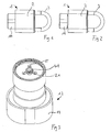
- FIG. 1 From the locking module is in FIG. 1 the actuating element, namely the rotary handle 11 visible, which is formed in the example shown as compared to a circular cylinder slightly flattened knob; Of course, any other shapes are conceivable.
- the lock housing and the bracket may have a known per se for padlocks or in another form. They can - which is also known per se - be metallic, for example. Of stainless steel.
- the locking module can be moved relative to the housing between two positions in the axial direction and forth.
- FIG. 2 shows the locking device with the locking module in the pulled-out position.
- the withdrawn position corresponds to the first coupling state ("generator operation").
- the device is in the second coupling state ("locking and unlocking").
- FIG. 3 shows the locking module 12 in a view.
- an electric motor not visible in the figure as well as electronic components of the electronic module are present.
- the latter include means for receiving data from an identification unit and for verifying access authorization based on the received data.
- they include an energy storage module for temporarily storing the electrical energy obtained - for example, one or more capacitors and / or possibly accumulators - and a control of the electric motor and, for example, means for signaling the power state and / or information on whether data received entitle to access.
- Such signaling means may be optical and / or acoustic (and include, for example, an LED and / or a piezo beeper).
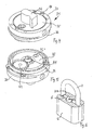
- FIG. 4 shows the transfer module 31 in an intent on the - seen from the locking bracket - top. It can be seen with respect to the axial direction not rotationally symmetrical locking part 32, which serves to cooperate with the locking means of the housing module.
- the transmission module has a stator element 33, which is designed to be annular in this case towards the upper side and, in the assembled state of the padlock, is fixed in its position and orientation relative to the housing module due to guide pins 34.
- the blocking part 32 is formed on a rotor element 35 and, for example, integral therewith and a part of this. Further, a rotatable relative to the stator element and the rotor element gear element 36 is formed, which is coupled in the assembled state of the padlock fixed to the locking module and rotatable by a rotation thereof.
- the transmission element 36 is formed as a toothed ring, in the teeth in the in FIG. 5 the first clutch state shown engage the teeth of a central gear 42 which is rotatably mounted on the rotor element 35.
- the middle gear 42 in turn cooperates with a central gear 41 which is mounted on the motor shaft 21.
- a planetary gear are translated by which rotations of the locking module relative to the housing and transmitted to the motor shaft 21.
- the motor can act as a generator by generating a forced rotational movement of the motor shaft 21 current and the energy can be stored in the energy storage module.
- the central gear 41 and the gear member 36 relative to the central gear 42 upwards (ie in the view FIG. 5 down) and so decoupled.
- the central gear 41 can then be used for locking and unlocking the padlock, which will be explained in more detail below.
- the coupling pin 15 of the locking module projects into a corresponding recess 35.1 of the rotor element 35 and rotatably couples this to the locking module.
- the rotor element serves as the intermediate element described above for locking the lock.
- the length of the coupling pin 15 is selected so that the coupling pin 15 does not protrude into the recess 35.1 in the first coupling state and permits a rotation of the locking module relative to the rotor element 35 necessary for the charging described above.
- FIG. 6 the housing module is shown.
- the locking means namely the locking pins 6, which engage in locking recesses 3.1 in the locking state and thus lock it relative to the housing.
- the locking member 32 In the assembled state of the padlock, the locking member 32 is in the space between the locking pin 6 and fixed depending on the position in the locked state or allows movement of the locking pin radially inwards. This is in the FIGS. 7 and 8 illustrated.
- FIG. 7 shows the locking member 32 in its Frei Anthonyung in which the locking pin can dodge inward, whereby the U-shaped bracket 3 in a conventional manner in the axial direction moved upwards and so the padlock can be unlocked.
- FIG. 8 the locking pins 6 are blocked by the locking member 32, and the padlock is locked.
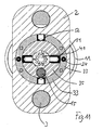
- FIG. 9 shows the padlock in the state in which the rotor element 35 is blocked relative to the stator element 33, wherein the locking device is in the first coupling state.
- On two opposite sides each have a pair of pins 51, 52 which are pressed in the manner of a tumbler (corresponding to the respective first pin 51) with Gegenzurois (corresponding to the respective second pin 52) by a spring force into a position in one of the two pins (in the illustrated embodiment, the second pin 52) locks the shear surface between the rotor element 35 and the stator element 33.
- the pin pairs 51, 52 can be moved counter to the spring force into a position in which said shear surface is released.
- the central gear 41 engages in a corresponding recess 54.1 of the eccentric element 54 and is rotatably coupled thereto.
- the eccentric element 54 is then brought into the orientation that in FIG. 10 is shown.
- the lateral surface of the eccentric element 54 acts as a control surface, which moves by the rotation of the pairs of pins to the outside. Since the interface between the first pin 51 and the second pin 52 of each pin pair in the position according to FIG. 10 coincides with the shear area between the rotor element 35 and the stator element 33, the rotor element (with the first pins 51) with respect to the stator element (with the second pins 52) can be rotated, which FIG. 11 is shown.
- the 'tumbler' may be longer (and the 'tumbler' correspondingly shorter) such that the shearing surface is released as the control surface of the eccentric member 54 correspondingly Fig. 9 is oriented. In the orientation of Fig. 10 then locks the 'tumbler' 51, the blocking area.
- This variant has the advantage that the shear line can not be released by violently shaking the whole device.
- FIG. 12 shows an overview of some existing in the locking module components.
- a rotational movement of the rotary handle 11 is transmitted via the transmission 61 to the motor 62 on.
- This generates electricity which is stored in energy storage means 64 (which, for example, have at least one capacitive element, for example a capacitor, for example an electrolytic capacitor).
- energy storage means 64 which, for example, have at least one capacitive element, for example a capacitor, for example an electrolytic capacitor.
- Depending on the type of motor still current rectifying means and / or other electronic components (not shown) interposed.
- the energy storage means 64 are used to power a processor element 65 and the motor 62 when used in the second coupling state to operate the locking device 63.
- the power supply of the motor can - as shown by the dashed arrow - directly (in which case only one control signal is transmitted from the processor element to the motor) or via the processor element 65.
- the processor element 65 is in communication with an antenna 66, via which non-contact data from the identification unit and possibly also to these are sent. This transfer can be done encrypted as known from the contactless information transfer.
- a motor As a motor, a commercially available or specially designed for the purpose engine can be used. Particularly suitable because of their simplicity are DC motors, but it can also stepper motors - these provide a particularly high voltage - or other motors are used.
- the identification units can be programmed without contact, for example, with a programming card before use. All necessary data such as access rights, time profiles, event memory and status information can be stored or stored in the electronic module of the device according to the invention and / or in the identification units. Changes to the configuration, such as deleting, adding or changing saved access rights and / or time profiles, can also be done using a programming medium. If the identification units are designed as externally at least partially conventional keys, they can be used in combined mechanical and / or mechatronic locking systems.
- the identification units are present, for example, as passive elements without their own power supply, as is known, for example, from RFID 'tags'. Alternatively or additionally, at least some identification units may also be active and battery powered.
- the interlocking devices can be operated from a comparatively large distance.
- identification units are active and battery-powered, they can be designed, for example, as programming media and only be available to selected users (as a kind of master).
- the data transmission for the programming takes place, for example, also without contact and, for example, encrypted, whereby information can be transmitted both from the identification unit to the electronic module of the device and vice versa.
- an active identification unit is capable of transferring energy to the electronic module without contact or via electrical contacts. This can be advantageous in the case of programming the electronic module and / or for an emergency opening in the event of a failure of the energy storage.
- the locking module and the transmission module can be used together in a lock cylinder, wherein a locking mechanism for a rotor of the cylinder and / or a coupling device to a driven element in a suitable manner with the rotor element 35th is actively connected.
- the locking device automatically the second Clutch state assumes after the energy storage means are charged.
- a spring may be present, against the force of which the displacement from the second, as standard assumed, coupling state to the second coupling state takes place.
- the device goes into the first coupling state, and the unlocking process can be triggered immediately upon receipt of data.
- capacitive-resistive coupling results in a very natural movement, since the user can carry the identification unit in the pocket and the data transmission automatically takes place by the touch of the device by the user.
- the locking device in the illustrated embodiment is substantially cylindrical, another external shape will also be possible.
- the profile of the locking device for example, the normalized Europrofil - or an equivalent profile, eg. According to other standards - correspond.
Landscapes
- Engineering & Computer Science (AREA)
- Computer Networks & Wireless Communication (AREA)
- Physics & Mathematics (AREA)
- General Physics & Mathematics (AREA)
- Lock And Its Accessories (AREA)
Description
Die Erfindung betrifft eine Verriegelungsvorrichtung für Schlösser, bspw. Vorhängeschlösser.The invention relates to a locking device for locks, for example. Padlocks.
Verriegelungsvorrichtungen mit elektronisch gesteuert betätigbaren Sperrelementen - mechatronische Verriegelungsvorrichtungen - sind bekannt. Die elektronisch gesteuerte Verriegelung basiert auf einer Datenübertragung zwischen einem schlüsselseitigen Elektronikmodul und einem schlossseitigen Elektronikmodul. Diese Datenübertragung kann durch Berührung - bspw. mittels elektrischer Kontakte an Schlüssel und Schloss - oder berührungslos - bspw. über Radiofrequenzübertragung - stattfinden. Daten können in nur eine oder in beide Richtungen übertragen werden.Locking devices with electronically controlled actuatable locking elements - mechatronic locking devices - are known. The electronically controlled locking is based on a data transmission between a key-side electronic module and a lock-side electronic module. This data transmission can take place by contact - for example by means of electrical contacts on key and lock - or without contact - for example via radio frequency transmission. Data can be transmitted in one or both directions.
Zumindest die schlossseitige Einheit der Verriegelungsvorrichtung benötigt im Allgemeinen eine Stromversorgung (eigene Batterie, Kontakt zu schlüsselseitiger Batterie, Netzanschluss), einerseits zum Betreiben des Elektronikmoduls, andererseits zum Betätigen der Sperrelemente. Ausserdem kann auch die Energieversorgung des schlüsselseitigen Elektronikmoduls von der schlossseitigen Einheit aus erfolgen, bspw. im Falle der RFID-Technik.At least the lock-side unit of the locking device generally requires a power supply (own battery, contact to key side battery, mains connection), on the one hand for operating the electronic module, on the other hand for actuating the blocking elements. In addition, the energy supply of the key-side electronic module can be made from the lock-side unit, for example in the case of RFID technology.
Insbesondere bei Schlössern, die nicht ohne Weiteres mit einem Stromnetz verbunden werden können, bspw. bei Vorhängeschlössern, bei Schlössern an Möbeln, an isoliert angebrachten Kästen im outdoor-Bereich etc. ist es üblich, das Schloss mit einem Batteriefach zu versehen. Ein Beispiel für ein elektronisches Vorhängeschloss mit Batterieversorgung ist in
In vielen Fällen ist jedoch eine solche Stromversorgung über eine Batterie nachteilig. So kommt es bspw. oft vor, dass ein Schloss über lange Zeit - im Extremfall über viele Monate oder gar ein Jahr oder mehr - nicht bedient wird. In solchen Fällen ist die Funktionstüchtigkeit des Schlosses keinesfalls gewährleistet, da eine Batterie inzwischen entladen oder gar ausgelaufen sein kann.In many cases, however, such a power supply via a battery is disadvantageous. For example, it often happens that a lock is not operated for a long time - in extreme cases over many months or even a year or more. In such cases, the functionality of the lock is not guaranteed, since a battery may be discharged or even leaked.
Aus der
Diese Doppelfunktion des Schrittmotors ist für ein Zahlenkombinationsschloss vorteilhaft, auf andere Anwendungen ist sie aber nicht übertragbar.This dual function of the stepping motor is advantageous for a combination lock, but it is not transferable to other applications.
In der Schrift
Es ist demnach Aufgabe der Erfindung, eine Verriegelungsvorrichtung zur Verfügung zu stellen, welche Nachteile von Verriegelungsvorrichtungen gemäss dem Stand der Technik überwindet und welche insbesondere für Anwendungen geeignet ist, bei denen nur beschränkt Platz zur Verfügung steht (bspw. Euro-Profil, US-Profil) und bei denen eine Stromversorgung über ein Stromversorgungsnetz nicht möglich und eine Stromversorgung durch eine Batterie nicht vorteilhaft ist.It is therefore an object of the invention to provide a locking device which overcomes disadvantages of locking devices according to the prior art and which is particularly suitable for applications in which only limited space is available (eg. Euro profile, US profile ) and in which a power supply via a power grid is not possible and a power supply by a battery is not advantageous.
Diese Aufgabe wird durch eine Verriegelungsvorrichtung gelöst, wie sie in den Patentansprüchen definiert ist.This object is achieved by a locking device as defined in the claims.
Die Verriegelungsvorrichtung besitzt wie an sich bekannt ein Elektronikmodul zum Empfangen von Daten von einer Identifikationseinheit (eine solche kann als Karte, bspw. Chipkarte oder in anderer Form ausgebildet sein und eventuell noch zusätzliche Funktionen wahrnehmen) und einen Elektromotor zum Betätigen einer Sperr- und/oder Kuppeleinrichtung für das Schloss, wobei der Motor durch das Elektronikmodul gesteuert werden kann. Die Verriegelungsvorrichtung zeichnet sich nun dadurch aus, dass sie in einen ersten und einen zweiten Kupplungszustand bringbar ist, wobei im ersten Kupplungszustand der Motor mit einem Betätigungselement gekoppelt ist und bei Betätigung des Betätigungselements als Generator wirkt. In einem zweiten Kupplungszustand ist der Motor mit der Sperr - und/oder Kuppeleinrichtung gekoppelt und kann das Schloss durch Betätigung dieser entriegeln.The locking device has as known per se an electronic module for receiving data from an identification unit (such may be formed as a card, eg. Chip card or other form and possibly even perform additional functions) and an electric motor for actuating a blocking and / or Coupling device for the lock, wherein the motor can be controlled by the electronic module. The locking device is characterized by the fact that it can be brought into a first and a second coupling state, wherein in the first coupling state, the motor is coupled to an actuating element and acts upon actuation of the actuating element as a generator. In a second coupling state, the motor is coupled to the locking and / or coupling device and can unlock the lock by actuating it.
Eine Verriegelung (als Umkehrvorgang des Entriegelns) des Schlosses kann ebenfalls durch den Motor bewirkbar sein, und/ oder es kann vorgesehen sein, dass durch geeignete Federmittel etc. die Verriegelungsvorrichtung unter den richtigen Voraussetzungen automatisch in den verriegelten Zustand gelangt.A lock (as a reverse operation of the unlocking) of the lock can also be effected by the motor, and / or it can be provided that by suitable spring means, etc., the locking device automatically gets into the locked state under the right conditions.
Das erfindungsgemässe Vorgehen ermöglicht eine autonome, von externer Stromversorgung und von Batterien unabhängige Lösung auch auf engem Raum, bspw. in einem Vorhängeschloss.The inventive method allows autonomous, independent of external power supply and batteries solution even in confined spaces, eg. In a padlock.
Das Betätigungselement ist von ausserhalb des Schlosses zugänglich und kann als Handgriff ausgebildet sein, bspw. als Drehknopf, - eventuell ausklappbares - Kurbelelement, etc.The actuator is accessible from outside the lock and can be designed as a handle, for example. As a knob, - possibly folding - crank element, etc.
Das Betätigungselement kann auch in der Art eines Schliesszylinder-Rotors ausgebildet und nur durch einen eingeführten mechanischen Schlüssel betätigbar sein. Ein solcher mechanischer Schlüssel kann in an sich bekannter Art Codierungsbohrungen aufweisen, die mit Zuhaltungs-Gegenzuhaldungspaaren des Betätigungselements zusammenwirken, wodurch das Betätigungselement nur bei passendem Schlüssel überhaupt betätigbar ist (und die Energiespeicher des Elektronikmoduls aufladbar sind). In dieser Variante kann - wie in anderen Varianten auch - ausserdem vorgesehen sein, dass die Ver-und Entriegelung des ganzen Schlosses im zweiten Kupplungszustand ebenfalls durch Betätigung Betätigungselements - bspw. durch eine Drehung um 90° oder 180° - erfolgt. Dann kann die richtige mechanische Codierung auch gleich eine Voraussetzung dafür sein, dass das Betätigungselement im zweiten Kupplungszustand betätigbar ist.The actuator may also be formed in the manner of a lock cylinder rotor and actuated only by an inserted mechanical key. Such a mechanical key can have coding holes in a manner known per se, which cooperate with tumbler counter pairs of the actuating element, whereby the actuating element can be actuated only when the key is in place (and the energy stores of the electronic module are rechargeable). In this variant can - as in other variants - also be provided that the locking and unlocking of the whole castle in the second coupling state also by actuating actuator - eg. By rotation through 90 ° or 180 ° - takes place. Then, the correct mechanical coding can also be a prerequisite for the actuation element to be actuatable in the second coupling state.
Ein solcher mechanischer Schlüssel kann gleichzeitig mit der Identifikationseinheit versehen sein, die Daten an das Elektronikmodul aussendet; dann kann er äusserlich ähnlich ausgebildet sein wie bereits bekannte Schlüssel von mechanischmechatronischen Schlössern. Solche Schlüssel haben oft ein Elektronikmodul im Handgriff eingebaut.Such a mechanical key may be provided simultaneously with the identification unit which transmits data to the electronic module; then he may be externally similar trained as already known key of mechanical mechatronic locks. Such keys have often incorporated an electronic module in the handle.
Vorzugsweise ist zwischen dem Betätigungselement und dem Motor ein Getriebe vorhanden, durch welches eine durch das es Betätigungselement erzeugbare (Dreh-) Bewegung übersetzt wird. Als Getriebe geeignet ist ein Planetengetriebe, da alle Zahnradelemente in einer Ebene angeordnet sein können und das anzutreibende mit der Welle des Motors verbundene Zahnrad dabei zentral liegen kann. Ebenfalls geeignet sind je nach Konfiguration andere Getriebe, bspw. Stirnradgetriebe. Das Getriebe kann in einem Motorblock integriert sein oder mindestens teilweise als separates Element (bspw. als Teil eines Übertragungsmoduls) ausgebildet sein.Preferably, there is a transmission between the actuating element and the motor, by means of which a (rotary) movement which can be generated by the actuating element is translated. Suitable gear is a planetary gear, since all gear elements can be arranged in a plane and the driven to be connected to the shaft of the motor gear can be centrally. Depending on the configuration, other transmissions, for example spur gears, are also suitable. The transmission may be integrated in an engine block or at least partially formed as a separate element (eg. As part of a transmission module).
Es kann alternativ auch vorgesehen sein, dass das Betätigungselement translatorisch zu bewegen ist und dass geeignete Getriebemittel diese translatorische Bewegung in eine Drehbewegung umlenken.Alternatively, it can also be provided that the actuating element is to be moved in translation and that suitable transmission means deflect this translatory movement into a rotational movement.
Die Kopplung zwischen dem Betätigungselement und dem Motor kann optional so eingerichtet sein, dass die übertragbare Kraft begrenzt ist, das heisst zwischen dem Betätigungselement und dem Motor kann (ggf. nebst einem Getriebe) ein Federelement, eine Schleifkupplung oder ein vergleichbares Mittel vorhanden sein, durch das bewirkt wird, dass bei übermässigem Krafteinsatz auf das Betätigungselement die auf den Motor einwirkende Kraft abgedämpft wird.The coupling between the actuating element and the motor can optionally be set up so that the transmittable force is limited, that is to say between the actuating element and the motor (possibly together with a gear) a spring element, a sliding clutch or a comparable means can be present the effect is that excessive force on the actuator, the force acting on the motor is damped.
Die Sperr- und/oder Kuppeleinrichtung kann wie an sich von Schliessvorrichtungen bekannt auf einem der folgendem Prinzipien beruhen:
- a. Versperren eines für die Entriegelung zu bewegenden Elements gegenüber einem anderen Element und Entsperren nur wenn eine Berechtigung vorliegt;
- b. Koppeln eines vom Benutzer bewegbaren Elements an ein zur Entriegelung zu bewegendes anderes Element nur dann, wenn eine Berechtigung vorliegt;
- c. Kombinationen von a. und b. und/oder mehrfache Anwendungen von a. und b.
- a. Locking an element to be moved for unlocking with respect to another element and unlocking only if there is an authorization;
- b. Coupling a user-movable element to a different element to be moved for unlocking only when authorized;
- c. Combinations of a. and b. and / or multiple applications of a. and b.
Nachfolgend wird die Erfindung mehrheitlich anhand des Prinzips a. beschrieben; dies ist aber nicht so auszulegen, dass nur Prinzip a. in Frage kommt; vielmehr können auch Vorrichtungen im Sinn der durch die Patentansprüche definierten Erfindung gemacht werden, die auf dem Prinzip b. oder c. beruhen.In the following, the invention will be based on the principle of principle a. described; but this is not to be construed so that only principle a. it is a possibility; Rather, devices can also be made in the sense of the invention defined by the claims, based on the principle b. or c. based.
Die Sperr- und/oder Kuppeleinrichtung besitzt gemäss einer speziellen Ausführungsform mindestens zwei Sperrmechanismus-Stufen. Mit einem zweiten Sperrmechanismus ist das Schloss selbst sperrbar. Wenn das Schloss bspw. ein Vorhängeschloss ist, versperrt der zweite Sperrmechanismus den Bügel des Vorhängeschlosses gegenüber dem Gehäuse. Wenn das Schloss ein Zylinderschloss ist, versperrt der zweite Sperrmechanismus den Rotor des Zylinders und/oder ein Abtriebselement und/oder ein Riegelelement gegenüber dem Gehäuse. Durch die erste Sperrmechanismus-Stufe ist gemäss dieser speziellen Ausführungsform ein von Hand zu betätigendes Zwischenelement gegenüber dem Gehäuse sperrbar, oder (gemäss obiger Option b.) mit einem weiteren Element koppelbar. Die erste Sperrmechanismus-Stufe wird durch den Motor betätigt, die zweite Sperrmechanismus-Stufe durch das Zwischenelement, d.h. das Entsperren auf der ersten Sperrmechanismus-Stufe ist eine Voraussetzung dafür, dass auf der zweiten Sperrmechanismus-Stufe entsperrt werden kann. Durch diese Zweistufigkeit wird bewirkt, dass auch bei Gewaltausübung durch Unbefugte keine Kräfte auf den Motor ausgeübt werden können.The locking and / or coupling device according to a special embodiment has at least two locking mechanism stages. With a second locking mechanism, the lock itself is lockable. For example, if the lock is a padlock, the second lock mechanism blocks the padlock against the housing. If the lock is a cylinder lock, locks the second locking mechanism, the rotor of the cylinder and / or an output member and / or a locking element relative to the housing. By the first locking mechanism stage is according to this particular embodiment, a manually operable intermediate element with respect to the housing lockable, or (according to the above option b.) Coupled with another element. The first lock mechanism stage is actuated by the motor, the second Locking mechanism stage through the intermediate element, ie the unlocking on the first locking mechanism stage is a prerequisite that can be unlocked on the second locking mechanism stage. This two-stage effect ensures that no force can be exerted on the engine even in the event of violence by unauthorized persons.
Der erste und der zweite Kupplungszustand können sich dadurch unterscheiden, dass eine Welle des Motors im ersten Kupplungszustand mit den Getriebemitteln und im zweiten Zustand mit einem Steuermechanismus in Wirkverbindung steht, welcher eine Sperrung und/oder eine Kupplung bewirkt.The first and second clutch states may be different in that a shaft of the engine is in operative connection with the transmission means in the first clutch state and in the second state with a control mechanism which effects a lock and / or a clutch.
Ein solcher Steuermechanismus kann bspw. ein Steuerelement aufweisen, das eine Steuerfläche besitzt und dadurch bei einer Drehung oder sonstiger Bewegung die Lage und/oder den Bewegungs(frei)raum von Sperrelementen beeinflusst. Dies ist bei einer zylindrischen Anordnung besonders günstig, kann doch durch eine solche Steuerfläche eine Drehbewegung auf einfachste Weise in eine radiale Bewegung umgesetzt werden. Beispielsweise können Sperrelemente durch eine Federkraft radial nach innen gegen die Steuerfläche gedrückt werden und sich bei Drehung des Steuerelementes entsprechend aufgrund der Federkraft oder entgegen der Federkraft radial verschieben und dadurch je nach Lage eine Scherfläche freigeben oder blockieren.Such a control mechanism may, for example, have a control which has a control surface and thereby influences the position and / or the movement (free) space of blocking elements during a rotation or other movement. This is particularly favorable in a cylindrical arrangement, but can be implemented by such a control surface a rotational movement in the simplest way in a radial movement. For example, locking elements can be pressed by a spring force radially inwardly against the control surface and move radially upon rotation of the control accordingly due to the spring force or against the spring force, thereby releasing or blocking a shear surface depending on the situation.
Im Falle von zwei Sperrmechanismus-Stufen gehört ein solches Steuerelement vorzugsweise zu der ersten Sperrmechanismus-Stufe.In the case of two lock mechanism stages, such a control preferably belongs to the first lock mechanism stage.
Alternativ dazu kann ein Steuerelement auch bewirken, dass ein Sperrelement selbst verschoben wird, bspw. unter Verwendung des Hubspindel-Prinzips.Alternatively, a control can also cause a locking element itself to be displaced, for example by using the lifting spindle principle.
Gemäss einer bevorzugten Ausführungsform ist die Verriegelungsvorrichtung modular aufgebaut und - gegebenenfalls mit geringfügigen Modifikationen - für verschiedene Schlosstypen geeignet. Sie kann als Ganze eine zylindrische Formgebung aufweisen. Alternativ dazu kann sie auch ein anderes, bspw. genormtes (bspw. Hahnprofil (DIN18252, auch Europrofil genannt) oder ähnliches Profil aufweisen. In einem solchen Fall besitzt die Verriegelungsvorrichtung eine Partie mit dem entsprechenden Profilzylinder-Querschnitt, wobei das Betätigungselement von dieser Partie vorsteht und einen grösseren Querschnitt haben kann - und im Allgemeinen auch hat.According to a preferred embodiment, the locking device is of modular construction and - possibly with minor modifications - suitable for different lock types. It can have a cylindrical shape as a whole. Alternatively, it may also have another, for example, standard (eg, Hahn profile (DIN 18252, also called Europrofil) or similar profile.) In such a case, the locking device has a lot with the corresponding profile cylinder cross-section, the actuating element projecting from this lot and can have a bigger cross-section - and in general too.
Die Verriegelungsvorrichtung kann - auch aufgrund eines solchen standardisierten äusseren Profils - in verschiedene Verschlusssysteme einfügbar sein. Ein den Elektromotor umfassendes Modul kann ausserdem ein gegen aussen hermetisch abschliessendes Gehäuse umfassen, das nur von einer Öffnung für die nach aussen ragende Welle unterbrochen wird, wobei diese Öffnung abgedichtet ist. Das Gehäuse kann teilweise metallisch sein, umfasst aber im Falle einer kontaktlosen Informationsübertragung vorzugsweise eine nicht-metallische Komponente, damit eine im Innern des Gehäuses angebrachte Antenne elektromagnetische Signale von aussen empfangen kann. Das Gehäuse kann auch als Ganzes nicht-metallisch, bspw. aus Kunststoff sein. Die Verriegelungsvorrichtung kann zusätzlich zum hier Beschriebenen auch eine rein mechanische Codierung aufweisen, so dass zusätzlich ein mit mechanischen Codierungen versehener Schlüssel verwendet werden muss, um das Schloss zu betätigen. Auch ein solcher Schlüssel kann zusätzlich die Identifikationseinheit beinhalten.The locking device can - also due to such a standardized outer profile - be inserted into different closure systems. A module comprising the electric motor may further comprise an externally hermetically sealed housing which is interrupted only by an opening for the outwardly projecting shaft, this opening being sealed. The housing may be partially metallic, but preferably comprises a non-metallic component in the case of contactless information transmission, so that an antenna mounted inside the housing can receive electromagnetic signals from outside. The housing may also be non-metallic as a whole, for example. Plastic. In addition to what is described here, the locking device may also have a purely mechanical coding, so that additionally a key provided with mechanical codings has to be used in order to actuate the lock. Such a key may additionally include the identification unit.
Bevorzugt erfolgt die Identifikation (d.h. das Übermitteln von Daten von der Identifikationseinheit an das Elektronikmodul und eventuell auch vom Elektronikmodul an die Identifikationseinheit) kontaktlos, beispielsweise mit RFID-Technologie. Ebenfalls möglich ist die Informationsübertragung mittels der kapazitiv-resistiven Kopplung durch den Benutzer, wie sie in der Schrift
Im Falle einer berührungslosen oder insbesondere auch einer kapazitiv-resistiven Informationsübertragung ergibt sich ein besonders natürlicher Bewegungsablauf beim Betätigen der Verriegelungsvorrichtung. So kann bspw. vorgesehen sein, dass die Identifikationseinheit lediglich am Körper - bspw. in der Hosentasche - zu tragen ist. Der Benutzer muss dann lediglich den Generator betätigen, indem er die Verriegelungsvorrichtung in den ersten Kupplungszustand bringt und das Betätigungselement bestimmungsgemäss bewegt. Während der Benutzer das macht oder unmittelbar danach kann gleich auch eine Informationsübertragung (über elektromagnetische Wellen und/oder kapazitiv/resistiv via den Körper des Benutzers erfolgen, so dass sich das Schloss unmittelbar nach dem Aufladen der Energiespeichermittel öffnen lässt.In the case of a non-contact or in particular a capacitive-resistive information transmission results in a particularly natural motion sequence when operating the locking device. Thus, for example, it may be provided that the identification unit is to be worn only on the body, for example in the trouser pocket. The user then only has to operate the generator by bringing the locking device in the first coupling state and moves the actuator as intended. While the user is doing this or immediately thereafter, an information transfer (via electromagnetic waves and / or capacitive / resistive via the user's body can take place immediately, so that the lock can be opened immediately after the energy storage medium has been charged.
Ebenfalls bevorzugt, was den Bewegungsablauf angeht, sind Ausführungsformen, bei denen die Vorrichtung selbsttätig vom ersten in den zweiten Kupplungszustand übergeht, bspw. durch eine Federkraft.Also preferred, as far as the movement sequence is concerned, are embodiments in which the device automatically transitions from the first to the second coupling state, for example by a spring force.
Es ist aber alternativ oder ergänzend dazu auch möglich, Informationen über elektrische und/oder optische etc. Kontakte auszutauschen, wobei Identifikationseinheit und Verriegelungsvorrichtung dann entsprechende Schnittstellen aufweisen.However, it is alternatively or additionally also possible to exchange information about electrical and / or optical etc. contacts, identification unit and locking device then having corresponding interfaces.
Eine erste wichtige Anwendung von erfindungsgemässen Verriegelungsvorrichtungen sind wie erwähnt Vorhängeschlösser, an die immer öfter ebenso wie für komplexere Schliessanlagen auch erhöhte Sicherheitsansprüche gestellt werden. So werden Vorhängeschlösser bspw. oft verwendet, um an abgelegen Orten die Infrastruktur von Mobiltelefonbetreibern etc. zu schützen. Solche Infrastruktur wird unter Umständen nur sporadisch gewartet, und es ist daher wichtig, dass eine Funktionstüchtigkeit auch gewährleistet ist, wenn das Schloss längere Zeit nicht betätigt wurde.A first important application of locking devices according to the invention are, as mentioned, padlocks to which more and more security requirements are being made, as well as for more complex locking systems. For example, padlocks are often used to protect the infrastructure of mobile operators, etc. in remote locations. Such infrastructure may only be maintained sporadically, and it is therefore important to ensure proper functioning even if the lock has not been operated for a long time.
Ebenfalls zur Anwendung kommen kann die erfindungsgemässe Vorrichtung im Zusammenhang mit Schliesszylindern, die nicht ohne Weiteres elektrisch versorgt sind, bspw. im Zusammenhang mit Schliesszylindern (unter diesen Begriff fallen hier auch 'Halbzylinder', d.h. nur einseitig betätigbare Schliesszylinder) für Möbel-/Vitrinen-/Schrankverschlüssen, Verschlüssen für Aussenschränke wie Elektrokästen, Ampelschränke, Energieverteiler etc., für Tore, Safes etc.The device according to the invention can also be used in connection with lock cylinders which are not readily supplied with electricity, for example in connection with lock cylinders (this term also includes 'half cylinders', ie lock cylinders which can only be actuated on one side) for furniture / showcases. / Cabinet closures, closures for external cabinets such as electrical boxes, traffic light cabinets, energy distributors, etc., for gates, safes, etc.
Zur Erfindung gehört also auch das vorstehend bereits dargelegte Konzept, eine Verriegelungsvorrichtung, insbesondere für Vorhängeschlösser, zur Verfügung zu stellen, bei der das Betätigungselement eine Doppelfunktion hat. Einerseits dient es dazu, bei Betätigung einen Generator anzutreiben, mit dem ein Energiespeicher für das Elektronikmodul aufgeladen wird. Andererseits dient es dazu, die Ver- und Entriegelung des ganzen Schlosses - ebenfalls durch mechanische Betätigung "von Hand" - vorzunehmen, bspw. indem das Verriegelungsmodul als ganzes gedreht wird. Zu diesem Zweck ist die Verriegelungsvorrichtung so ausgelegt, dass sie vom Elektronikmodul gesteuert in einen ersten und in einen zweiten Kupplungszustand bringbar ist. Im ersten Kupplungszustand bewirkt eine Betätigung (bspw. Drehung) des Betätigungselements ein Aufladen des Energiespeichers über den Generator. Im zweiten Kupplungszustand bewirkt eine Betätigung (bspw. Drehung) des Betätigungselements eine Ver- bzw. Entriegelung des Schlosses.The invention thus also includes the concept already outlined above of providing a locking device, in particular for padlocks, in which the actuating element has a double function. On the one hand, it serves, when actuated, to drive a generator with which an energy store for the electronic module is charged. On the other hand, it serves to make the locking and unlocking of the whole castle - also by mechanical operation "by hand" -, for example. By the locking module is rotated as a whole. For this purpose, the locking device is designed so that it is controlled by the electronic module in a first and in a second coupling state can be brought. In the first coupling state, an actuation (for example rotation) of the actuating element causes a charging of the energy store via the generator. In the second coupling state, an actuation (for example rotation) of the actuating element causes a locking or unlocking of the lock.
Der elektrische Antrieb (bspw. Elektromotor), den Übergang zwischen vom ersten in dem zweiten Kopplungszustand (und optional auch den umgekehrten Übergang vom zweiten in den ersten Kopplungszustand) bewirkt, kann gemäss dem vorstehend beschriebenen Aspekt mit dem Generator identisch sein.The electric drive (eg electric motor), which causes the transition between the first in the second coupling state (and optionally also the reverse transition from the second to the first coupling state) may, according to the aspect described above, be identical to the generator.
Nachfolgend werden bevorzugte Ausführungsformen der Erfindung anhand von Zeichnungen näher beschrieben. In den Zeichnungen zeigen:
-
Fig. 1 und 2 Ansichten eines erfindungsgemässen Vorhängeschlosses; -
Fig. 3 eine Ansicht eines Verriegelungsmoduls eines Vorhängeschlosses; -
Fig. 4 und 5 Ansichten eines Übertragungsmoduls eines Vorhängeschlosses; -
Fig. 6 eine Darstellung eines Gehäusemoduls eines Vorhängeschlosses; -
Fig. 7 und 8 Darstellungen, die die Verriegelung des Bügels illustrieren; -
Fig. 9-11 schematisierte Schnittdarstellungen des Vorhängeschlosses, die die Funktionsweise der zweiten Sperrmechanismus-Stufe zeigen; -
Fig. 12 ein Schema von Komponenten der Verriegelungsvorrichtung.
-
Fig. 1 and 2 Views of a padlock according to the invention; -
Fig. 3 a view of a lock module of a padlock; -
4 and 5 Views of a transfer module of a padlock; -
Fig. 6 an illustration of a housing module of a padlock; -
FIGS. 7 and 8 Illustrations illustrating the locking of the bracket; -
Fig. 9-11 schematic sectional views of the padlock showing the operation of the second lock mechanism stage; -
Fig. 12 a schematic of components of the locking device.
Das Vorhängeschloss 1 gemäss
Gehäusemodul mit Schlossgehäuse 2,U-förmigem Bügel 3 und Arretiermitteln,- Verriegelungsmodul,
- Übertragungsmodul.
- Housing module with
lock housing 2,U-shaped bracket 3 and locking means, - Locking module
- Transmission module.
Das Verriegelungsmodul und das Übertragungsmodul bilden zusammen die Verriegelungsvorrichtung des Vorhängeschlosses.The locking module and the transmission module together form the locking device of the padlock.
Vom Verriegelungmodul ist in
Das Schlossgehäuse und der Bügel können eine an sich für Vorhängeschlösser bekannte Form oder auch in einer anderen Form aufweisen. Sie können - was ebenfalls an sich bekannt ist - metallisch sein, bspw. aus rostfreiem Stahl.The lock housing and the bracket may have a known per se for padlocks or in another form. They can - which is also known per se - be metallic, for example. Of stainless steel.
Das Verriegelungsmodul kann relativ zum Gehäuse zwischen zwei Stellungen in axialer Richtung hin und herbewegt werden.The locking module can be moved relative to the housing between two positions in the axial direction and forth.
Vom Elektromotor sieht man in
Das Übertragungsmodul besitzt ein hier zur Oberseite hin ringförmig ausgebildetes Stator-Element 33 , welches im zusammengesetzten Zustand des Vorhängeschlosses aufgrund von Führungsstiften 34 in seiner Position und Orientierung relativ zum Gehäusemodul fix ist. Das Sperrteil 32 an einem Rotor-Element 35 ausgebildet und bspw. einstückig mit diesem und ein Teil von diesem. Weiter ist ein relativ zum Stator-Element und zum Rotor-Element drehbares Getriebeelement 36 ausgebildet, welches im zusammengesetzten Zustand des Vorhängeschlosses fest an das Verriegelungsmodul gekoppelt und durch eine Drehung desselben drehbar ist.The transmission module has a
In
Im zweiten Kupplungszustand werden das zentrale Zahnrad 41 und das Getriebeelement 36 relativ zum mittleren Zahnrad 42 nach oben (d.h. in der Ansicht gemäss
Im zweiten Kupplungszustand ragt der Kupplungsstift 15 des Verriegelungsmoduls in eine entsprechende Aussparung 35.1 des Rotor-Elements 35 hinein und kuppelt dieses drehfest an das Verriegelungsmodul. In diesem Zustand kann also das Vorhängeschloss durch Drehung des Verriegelungsmoduls 1 um einen bestimmten Winkel, hier 90° - sofern letzteres nicht gegen eine solche verriegelt ist - verriegelt oder entriegelt werden, was man anhand der nachfolgenden
Die Länge des Kupplungsstifts 15 ist so gewählt, dass der Kupplungsstift 15 im ersten Kupplungszustand nicht in die Aussparung 35.1 hineinragt und eine für das vorstehend beschriebene Aufladen notwendige Drehung des Verriegelungsmoduls relativ zum Rotor-Element 35 erlaubt.The length of the
In
Anhand von
Im zweiten Kupplungszustand greift das zentrale Zahnrad 41 in eine entsprechende Aussparung 54.1 des exzentrischen Elements 54 ein und wird drehfest an diese gekoppelt. Durch vom Motor angetriebene Drehung der Motorwelle - im gezeichneten Beispiel um 90° - wird das exzentrische Element 54 dann in die Orientierung gebracht, die in
Natürlich sind auch andere Konfigurationen als die in
Die Energiespeichermittel 64 werden zur Stromversorgung eines Prozessorelements 65 sowie des Motors 62 verwendet, wenn dieser im zweiten Kupplungszustand zum Betätigen der Sperreinrichtung 63 verwendet wird. Die Stromversorgung des Motors kann - wie durch den gestrichelten Pfeil dargestellt - direkt (wobei dann vom Prozessorelement an den Motor nur ein Steuersignal übertragen wird) oder auch über das Prozessorelement 65 erfolgen.The energy storage means 64 are used to power a
Das Prozessorelement 65 steht in Verbindung mit einer Antenne 66, über welche berührungslos Daten von der Identifikationseinheit empfangen und eventuell auch an diese gesendet werden. Diese Übertragung kann wie an sich von der berührungslosen Informationsübertragung bekannt verschlüsselt erfolgen.The
Ein optionales Signalisations-Mittel 67 - hier als LED dargestellt; das Signalisationsmittel kann optisch und/oder akustisch sein - kann ebenfalls über das Prozessorelement 65 gesteuert und mit Energie versorgt sein.An optional signaling means 67 - shown here as an LED; the signaling means may be optical and / or acoustic - may also be controlled and powered by the
Als Motor kann ein handelsüblicher oder speziell für den Zweck konstruierter Motor verwendet werden. Besonders geeignet aufgrund ihrer Einfachheit sind Gleichstrommotoren, es können aber auch Schrittmotoren - diese liefern eine speziell hohe Spannung - oder andere Motoren verwendet werden.As a motor, a commercially available or specially designed for the purpose engine can be used. Particularly suitable because of their simplicity are DC motors, but it can also stepper motors - these provide a particularly high voltage - or other motors are used.
Die Identifikationseinheiten (bspw. Schlüssel oder Karten) können vor dem Gebrauch bspw. mit einer Programmierkarte kontaktlos programmiert werden. Alle notwendigen Daten wie Zutrittsrechte, Zeitprofile, Ereignisspeicher und Statusinformationen können im Elektronikmodul der erfindungsgemässen Vorrichtung und/oder in den Identifikationseinheiten gespeichert werden bzw. gespeichert sein. Auch Änderungen der Konfiguration wie löschen, hinzufügen oder ändern von gespeicherten Zutrittsrechten und/oder Zeitprofilen können mittels eines Programmiermediums erfolgen. Wenn die Identifikationseinheiten als äusserlich mindestens teilweise konventionelle Schlüssel ausgebildet sind, können sie in kombinierten mechanischen und/oder mechatronischen Schliessanlagen verwendet werden.The identification units (eg keys or cards) can be programmed without contact, for example, with a programming card before use. All necessary data such as access rights, time profiles, event memory and status information can be stored or stored in the electronic module of the device according to the invention and / or in the identification units. Changes to the configuration, such as deleting, adding or changing saved access rights and / or time profiles, can also be done using a programming medium. If the identification units are designed as externally at least partially conventional keys, they can be used in combined mechanical and / or mechatronic locking systems.
Die Identifikationseinheiten sind beispielsweise als passive Elemente ohne eigene Energieversorgung vorhanden, wie das bspw. von RFID-'Tags' bekannt ist. Alternativ oder ergänzend dazu können mindestens einige - Identifikationseinheiten auch aktiv und batteriebetrieben sein.The identification units are present, for example, as passive elements without their own power supply, as is known, for example, from RFID 'tags'. Alternatively or additionally, at least some identification units may also be active and battery powered.
In einem System, in welchem alle Identifikationseinheiten aktiv und batteriebetrieben sind, können die Verriegelungsvorrichtungen aus vergleichsweise grosser Entfernung bedient werden.In a system in which all identification units are active and battery powered, the interlocking devices can be operated from a comparatively large distance.
Wenn nur einige Identifikationseinheiten mit aktiv und batteriebetrieben sind, können diese bspw. als Programmiermedien ausgebildet und nur ausgesuchten Benutzern (quasi als Master) zur Verfügung stehen. Die Datenübertragung für die Programmierung erfolgt bspw. ebenfalls kontaktlos und bspw. verschlüsselt, wobei Informationen sowohl von der Identifikationseinheit zum Elektronikmodul der Vorrichtung als auch umgekehrt übertragen werden kann. Es kann auch vorgesehen sein, dass eine solche aktive Identifikationseinheit in der Lage ist, Energie kontaktlos oder über elektrische Kontakte an das Elektronikmodul zu übertragen. Dies kann im Falle der Programmierung des Elektronikmoduls und/oder für eine Notöffnung im Falle eines Defekts des Energiespeichers von Vorteil sein.If only a few identification units are active and battery-powered, they can be designed, for example, as programming media and only be available to selected users (as a kind of master). The data transmission for the programming takes place, for example, also without contact and, for example, encrypted, whereby information can be transmitted both from the identification unit to the electronic module of the device and vice versa. It can also be provided that such an active identification unit is capable of transferring energy to the electronic module without contact or via electrical contacts. This can be advantageous in the case of programming the electronic module and / or for an emergency opening in the event of a failure of the energy storage.
Für die Verwendung der erfindungsgemässen Verriegelungsvorrichtung für andere Schlösser als Vorhängeschlösser können beispielsweise das Verriegelungsmodul und das Übertragungsmodul zusammen in einen Schlosszylinder eingesetzt werden, wobei ein Versperrmechanismus für einen Rotor des Zylinders und/oder eine Kupplungseinrichtung an ein Abtriebselement auf geeignete Weise mit dem Rotor-Element 35 wirkverbunden wird.For the use of the locking device according to the invention for locks other than padlocks, for example, the locking module and the transmission module can be used together in a lock cylinder, wherein a locking mechanism for a rotor of the cylinder and / or a coupling device to a driven element in a suitable manner with the rotor element 35th is actively connected.
Zusätzlich zu den gezeichneten und vorstehend beschriebenen Merkmalen kann vorgesehen sein, dass die Verriegelungsvorrichtung selbsttätig den zweiten Kupplungszustand einnimmt, nachdem die Energiespeichermittel aufgeladen sind. Bspw. kann eine Feder vorhanden sein, entgegen deren Kraft die Verschiebung vom zweiten, standardmässig eingenommenen Kupplungszustand in den zweiten Kupplungszustand erfolgt. Nachdem der Benutzer das Betätigungselement nach dem Aufladen loslässt geht die Vorrichtung in den ersten Kupplungszustand über, und der Entriegelungsvorgang kann bei entsprechendem Empfang von Daten sogleich ausgelöst werden. Beispielsweise im Falle der vorstehend erwähnten kapazitiv-resistiven Kopplung ergibt sich ein sehr natürlicher Bewegungsablauf, da der Benutzer die Identifikationseinheit in der Tasche tragen kann und die Datenübertragung durch die Berührung der Vorrichtung durch den Benutzer automatisch erfolgt.In addition to the drawn and described above features can be provided that the locking device automatically the second Clutch state assumes after the energy storage means are charged. For example. a spring may be present, against the force of which the displacement from the second, as standard assumed, coupling state to the second coupling state takes place. After the user lets go of the actuator after charging, the device goes into the first coupling state, and the unlocking process can be triggered immediately upon receipt of data. For example, in the case of the above-mentioned capacitive-resistive coupling results in a very natural movement, since the user can carry the identification unit in the pocket and the data transmission automatically takes place by the touch of the device by the user.
Die Fachperson wird bei Kenntnis der Erfindung weitere Ausgestaltungen realisieren können. Beispielsweise für den durch den Motor betätigten Sperr- bzw. Kupplungsmechanismus gibt es unzählige Möglichkeiten, mit oder ohne Kombination mit rein mechanischen Sicherheitselementen.The skilled person will be able to realize further embodiments with knowledge of the invention. For example, for the motorized by the locking mechanism or clutch mechanism, there are innumerable possibilities, with or without combination with purely mechanical security elements.
Während beispielsweise die Verriegelungsvorrichtung in der gezeichneten Ausführungsform im Wesentlichen zylindrisch ist, wird auch eine andere äussere Form möglich sein. So kann das Profil der Verriegelungsvorrichtung bspw. dem normierten Europrofil - oder einem äquivalenten Profil, bspw. entsprechend anderer Normen - entsprechen. In einem solchen Fall besteht nebst Anderem die Möglichkeit, im nicht-zylindrischen Teil der Verriegelungsvorrichtung Elemente eines Stirnradgetriebes anzuordnen.For example, while the locking device in the illustrated embodiment is substantially cylindrical, another external shape will also be possible. Thus, the profile of the locking device, for example, the normalized Europrofil - or an equivalent profile, eg. According to other standards - correspond. In such a case, among other things, it is possible to arrange elements of a spur gear in the non-cylindrical part of the locking device.
Viele weitere Varianten der durch die Patentansprüche definierten Erfindung sind denkbar.Many other variants of the invention defined by the claims are conceivable.
Claims (15)
- A locking device for a lock, comprising an electronics module for receiving data from an identification unit, and also comprising an electric motor for actuating a blocking device and/or coupling device, by way of which the lock can be locked and unlocked depending on data received by the electronics module, characterised in that the locking device can be brought into a first and a second coupling condition, wherein in the first coupling condition, the electric motor is coupled to an actuation element, and on actuation of the actuation element acts as a generator and charges energy storage means for the electronics module, and in a second coupling condition is coupled to the blocking device and/or coupling device.
- A locking device according to claim 1, characterised in that a shaft of the electric motor in the first coupling condition is in active connection with the actuation element and in the second condition is in active connection with a control mechanism which effects a blocking and/or coupling.
- A locking device according to claim 2, characterised by gear means by way of which, in the first coupling condition, a rotation movement produced by the actuation means is transmitted to the shaft in a stepped-up manner, wherein preferably the gear or a part of the gear is designed as a planetary gear.
- A locking device according to one of the preceding claims, characterised in that the actuation element is a rotary grip.
- A locking device according to one of the preceding claims, characterised in that the electric motor in the second coupling condition is actively connected to a control element which has a control surface and with a rotation influences the position and/or the movement space of at least one blocking means.
- A locking device according to one of the preceding claims, characterised in that the blocking device and/or coupling device has at least two blocking mechanism stages, wherein an intermediate element is blockable with respect to the housing as the first blocking mechanism stage and the lock is blockable by the intermediate element as a second blocking mechanism stage.
- A locking device according to one of the preceding claims, characterised in that the electronics module comprises means for the contact-less receiving and/or sending of signals.
- A locking device according to one of the preceding claims, characterised in that the electronics module comprises means for receiving and/or sending signals, by way of the capacitive-resistive coupling.
- A locking device according to one of the preceding claims, characterised by additional means for receiving electrical energy from an active medium which does not belong to the lock and is not permanently connected to this, by which means an operation is possible also in the case of a failure of the energy storage means.
- A locking device according to one of the preceding claims, characterised in that the locking device is movable between the first and the second coupling condition, by way of a hand movement, for example a translatory displacement of the actuation element.
- A locking device according to one of the preceding claims, characterised by means for automatically bringing the device from the first into the second coupling condition.
- A locking device according to one of the preceding claims, characterised in that the locking device in the locked condition can be brought in a manner controlled by the electronics module from a first into a second coupling condition, wherein an actuation of the actuation element in the first coupling condition effects a charging of an energy storer for the electronics module and for the electronically controllable drive, via a generator, and in the second coupling condition effects an unlocking of the lock.
- A locking device according to one of the preceding claims, characterised in that disregarding a head part with the actuation element, it has an outer cross section corresponding to a standardised locking cylinder profile, for example according to the profile DIN18252.
- A lock, comprising a locking device according to one of the preceding claims.
- A lock according to claim 14, characterised in that it is a padlock and has a padlock housing and a shackle, wherein the shackle can be locked with respect to the padlock housing by way of the locking device.
Applications Claiming Priority (2)
| Application Number | Priority Date | Filing Date | Title |
|---|---|---|---|
| CH14632007 | 2007-09-19 | ||
| PCT/CH2008/000388 WO2009036585A1 (en) | 2007-09-19 | 2008-09-18 | Locking device |
Publications (2)
| Publication Number | Publication Date |
|---|---|
| EP2201535A1 EP2201535A1 (en) | 2010-06-30 |
| EP2201535B1 true EP2201535B1 (en) | 2012-10-24 |
Family
ID=40193889
Family Applications (1)
| Application Number | Title | Priority Date | Filing Date |
|---|---|---|---|
| EP08800434A Active EP2201535B1 (en) | 2007-09-19 | 2008-09-18 | Locking device |
Country Status (2)
| Country | Link |
|---|---|
| EP (1) | EP2201535B1 (en) |
| WO (1) | WO2009036585A1 (en) |
Cited By (1)
| Publication number | Priority date | Publication date | Assignee | Title |
|---|---|---|---|---|
| CN111877876A (en) * | 2020-06-28 | 2020-11-03 | 万晖五金(深圳)有限公司 | Electronic padlock, control method and control device |
Families Citing this family (17)
| Publication number | Priority date | Publication date | Assignee | Title |
|---|---|---|---|---|
| CH700674A1 (en) | 2009-03-30 | 2010-09-30 | Keso Ag | Mechatronic closing. |
| DE102009040426B4 (en) * | 2009-09-07 | 2015-10-15 | Emz-Hanauer Gmbh & Co. Kgaa | Access device, in particular for a refuse disposal facility |
| DE102010021104B3 (en) * | 2010-05-20 | 2011-10-13 | Matthias Plath | Digital hang lock |
| US20120186308A1 (en) | 2011-01-20 | 2012-07-26 | Abus August Bremicker Soehne Kg | Padlock for securing and monitoring a switch |
| DE102011009011B4 (en) * | 2011-01-20 | 2023-10-05 | ABUS August Bremicker Söhne Kommanditgesellschaft | Padlock for securing and monitoring a switch |
| FR2982302B1 (en) * | 2011-11-09 | 2014-11-07 | Thirard Ets | ELECTROMECHANICAL LATCH |
| DE102012017820B4 (en) | 2012-09-08 | 2025-02-06 | Gantner Electronic Gmbh | Method and device for operating a cabinet lock of a central locking system with energy generation |
| CN103306556B (en) * | 2013-05-16 | 2016-04-13 | 上海冠军贸易有限公司 | A kind of luggage case with secure identification system |
| DE102014105432B4 (en) * | 2014-04-16 | 2016-01-07 | Uhlmann & Zacher Gmbh | Self-feeding knob cylinder |
| TWI658194B (en) | 2014-05-19 | 2019-05-01 | 黎巴嫩商艾克瑟斯智權控股公司 | Mobile key devices systems and methods for programming and communicating with an electronic programmable key |
| US10013825B2 (en) | 2015-03-03 | 2018-07-03 | Acsys Ip Holding, Inc. | Systems and methods for redundant access control systems based on mobile devices |
| US9852562B2 (en) | 2015-07-06 | 2017-12-26 | Acsys Ip Holding, Inc. | Systems and methods for redundant access control systems based on mobile devices and removable wireless buttons |
| US9672674B2 (en) | 2015-07-06 | 2017-06-06 | Acsys Ip Holding, Inc. | Systems and methods for secure lock systems with redundant access control |
| WO2018184070A1 (en) | 2017-04-05 | 2018-10-11 | Assa Abloy Australia Pty Limited | Electronically controlled padlock |
| FR3124537B1 (en) * | 2021-06-23 | 2023-06-16 | Kickmaker | Electric padlock system without battery |
| DE102021122250B3 (en) * | 2021-08-27 | 2022-10-27 | ABUS August Bremicker Söhne Kommanditgesellschaft | Mobile electronic lock |
| SE547180C2 (en) * | 2023-05-19 | 2025-05-20 | Assa Abloy Ab | A padlock comprising an energy harvesting device |
Family Cites Families (7)
| Publication number | Priority date | Publication date | Assignee | Title |
|---|---|---|---|---|
| DE4019624C2 (en) * | 1990-06-20 | 2000-05-25 | Fliether Karl Gmbh & Co | Double lock cylinder with an electrical locking device |
| US5265452A (en) * | 1991-09-20 | 1993-11-30 | Mas-Hamilton Group | Bolt lock bolt retractor mechanism |
| US6047575A (en) * | 1995-05-19 | 2000-04-11 | Slc Technologies, Inc. | Electronic padlock |
| AU2089199A (en) * | 1997-12-12 | 1999-06-28 | Mas-Hamilton Group, Inc. | A drive and control system for power generation and pulse generation in an electronic lock |
| DE19829927C2 (en) * | 1998-07-04 | 2001-01-25 | Drumm Sicherheit Gmbh | Electronic door fitting |
| DK199900474A (en) * | 1999-04-12 | 2000-10-13 | Stroebech Kristian Dogel | Electronic locking mechanism |
| DE102005022930A1 (en) * | 2005-05-15 | 2006-11-16 | Gunter Kries | Locking/unlocking system for plants, machines and buildings has electrically controlled locking component supplied from manually operated generator and which is operated depending upon state of at least one electrical contact |
-
2008
- 2008-09-18 EP EP08800434A patent/EP2201535B1/en active Active
- 2008-09-18 WO PCT/CH2008/000388 patent/WO2009036585A1/en not_active Ceased
Cited By (1)
| Publication number | Priority date | Publication date | Assignee | Title |
|---|---|---|---|---|
| CN111877876A (en) * | 2020-06-28 | 2020-11-03 | 万晖五金(深圳)有限公司 | Electronic padlock, control method and control device |
Also Published As
| Publication number | Publication date |
|---|---|
| WO2009036585A1 (en) | 2009-03-26 |
| EP2201535A1 (en) | 2010-06-30 |
Similar Documents
| Publication | Publication Date | Title |
|---|---|---|
| EP2201535B1 (en) | Locking device | |
| EP1576246B1 (en) | Locking device | |
| AT515703B1 (en) | LOCKING DEVICE | |
| DE19930054C2 (en) | Electromechanical locking system | |
| DE19848286B4 (en) | Coupling assembly for an electromechanical locking system | |
| EP2728092B1 (en) | Self-powered door lock | |
| EP1256671B1 (en) | Escutcheon for a lock cylinder | |
| DE102014105432B4 (en) | Self-feeding knob cylinder | |
| DE102004046778B4 (en) | Lock cylinder with increased security | |
| EP2998487B1 (en) | Lock and electronic locking system | |
| EP0805905B1 (en) | Door-closing mechanism | |
| DE102007011554B4 (en) | Coupling unit for electronic locking systems | |
| EP1662076B1 (en) | Coupling device for a locking arrangement | |
| DE19602438C2 (en) | Combination lock | |
| DE102020112966B3 (en) | Actuating device for a hydrant, hydrant system and water extraction valve | |
| EP1736622A1 (en) | Knob cylinder | |
| DE102009018471B4 (en) | Lock box with piezo motor | |
| DE112007002578B4 (en) | lock cylinder | |
| DE202024000962U1 (en) | Fire protection closure or closing device, in particular with or in the form of a fire door or flap | |
| DE102005034325A1 (en) | Fitting for access control device for door, has housing protrusion facing door panel and designed to fit into cylindrical hole provided for lock cylinder instead of lock cylinder | |
| DE19726010A1 (en) | Lock for furniture compartments, shops, locker, doors, etc. | |
| EP3848541B1 (en) | Lock | |
| EP4729719A1 (en) | Lock for a piece of furniture | |
| DE102004018339A1 (en) | Door lock has coupling element between mechanical lock cylinder(s), coupling device that moves axially to move coupling device drive element to open position when mechanical lock cylinder turned from initial position to end position | |
| EP3131068A1 (en) | Cabinet door lock communicating wirelessly with a central unit |
Legal Events
| Date | Code | Title | Description |
|---|---|---|---|
| PUAI | Public reference made under article 153(3) epc to a published international application that has entered the european phase |
Free format text: ORIGINAL CODE: 0009012 |
|
| 17P | Request for examination filed |
Effective date: 20100414 |
|
| AK | Designated contracting states |
Kind code of ref document: A1 Designated state(s): AT BE BG CH CY CZ DE DK EE ES FI FR GB GR HR HU IE IS IT LI LT LU LV MC MT NL NO PL PT RO SE SI SK TR |
|
| AX | Request for extension of the european patent |
Extension state: AL BA MK RS |
|
| RIN1 | Information on inventor provided before grant (corrected) |
Inventor name: BURGER, THOMAS Inventor name: ASCHMANN, ALFRED |
|
| DAX | Request for extension of the european patent (deleted) | ||
| GRAP | Despatch of communication of intention to grant a patent |
Free format text: ORIGINAL CODE: EPIDOSNIGR1 |
|
| GRAS | Grant fee paid |
Free format text: ORIGINAL CODE: EPIDOSNIGR3 |
|
| GRAA | (expected) grant |
Free format text: ORIGINAL CODE: 0009210 |
|
| AK | Designated contracting states |
Kind code of ref document: B1 Designated state(s): AT BE BG CH CY CZ DE DK EE ES FI FR GB GR HR HU IE IS IT LI LT LU LV MC MT NL NO PL PT RO SE SI SK TR |
|
| REG | Reference to a national code |
Ref country code: GB Ref legal event code: FG4D Free format text: NOT ENGLISH |
|
| REG | Reference to a national code |
Ref country code: CH Ref legal event code: EP |
|
| REG | Reference to a national code |
Ref country code: AT Ref legal event code: REF Ref document number: 581278 Country of ref document: AT Kind code of ref document: T Effective date: 20121115 |
|
| REG | Reference to a national code |
Ref country code: IE Ref legal event code: FG4D Free format text: LANGUAGE OF EP DOCUMENT: GERMAN |
|
| REG | Reference to a national code |
Ref country code: CH Ref legal event code: NV Representative=s name: FREI PATENTANWALTSBUERO AG, CH |
|
| REG | Reference to a national code |
Ref country code: DE Ref legal event code: R096 Ref document number: 502008008510 Country of ref document: DE Effective date: 20121220 |
|
| REG | Reference to a national code |
Ref country code: SE Ref legal event code: TRGR |
|
| REG | Reference to a national code |
Ref country code: NL Ref legal event code: VDEP Effective date: 20121024 |
|
| PG25 | Lapsed in a contracting state [announced via postgrant information from national office to epo] |
Ref country code: HR Free format text: LAPSE BECAUSE OF FAILURE TO SUBMIT A TRANSLATION OF THE DESCRIPTION OR TO PAY THE FEE WITHIN THE PRESCRIBED TIME-LIMIT Effective date: 20121024 Ref country code: ES Free format text: LAPSE BECAUSE OF FAILURE TO SUBMIT A TRANSLATION OF THE DESCRIPTION OR TO PAY THE FEE WITHIN THE PRESCRIBED TIME-LIMIT Effective date: 20130204 Ref country code: IS Free format text: LAPSE BECAUSE OF FAILURE TO SUBMIT A TRANSLATION OF THE DESCRIPTION OR TO PAY THE FEE WITHIN THE PRESCRIBED TIME-LIMIT Effective date: 20130224 Ref country code: NL Free format text: LAPSE BECAUSE OF FAILURE TO SUBMIT A TRANSLATION OF THE DESCRIPTION OR TO PAY THE FEE WITHIN THE PRESCRIBED TIME-LIMIT Effective date: 20121024 Ref country code: NO Free format text: LAPSE BECAUSE OF FAILURE TO SUBMIT A TRANSLATION OF THE DESCRIPTION OR TO PAY THE FEE WITHIN THE PRESCRIBED TIME-LIMIT Effective date: 20130124 Ref country code: FI Free format text: LAPSE BECAUSE OF FAILURE TO SUBMIT A TRANSLATION OF THE DESCRIPTION OR TO PAY THE FEE WITHIN THE PRESCRIBED TIME-LIMIT Effective date: 20121024 |
|
| PG25 | Lapsed in a contracting state [announced via postgrant information from national office to epo] |
Ref country code: PL Free format text: LAPSE BECAUSE OF FAILURE TO SUBMIT A TRANSLATION OF THE DESCRIPTION OR TO PAY THE FEE WITHIN THE PRESCRIBED TIME-LIMIT Effective date: 20121024 Ref country code: LV Free format text: LAPSE BECAUSE OF FAILURE TO SUBMIT A TRANSLATION OF THE DESCRIPTION OR TO PAY THE FEE WITHIN THE PRESCRIBED TIME-LIMIT Effective date: 20121024 Ref country code: PT Free format text: LAPSE BECAUSE OF FAILURE TO SUBMIT A TRANSLATION OF THE DESCRIPTION OR TO PAY THE FEE WITHIN THE PRESCRIBED TIME-LIMIT Effective date: 20130225 Ref country code: GR Free format text: LAPSE BECAUSE OF FAILURE TO SUBMIT A TRANSLATION OF THE DESCRIPTION OR TO PAY THE FEE WITHIN THE PRESCRIBED TIME-LIMIT Effective date: 20130125 Ref country code: SI Free format text: LAPSE BECAUSE OF FAILURE TO SUBMIT A TRANSLATION OF THE DESCRIPTION OR TO PAY THE FEE WITHIN THE PRESCRIBED TIME-LIMIT Effective date: 20121024 |
|
| PG25 | Lapsed in a contracting state [announced via postgrant information from national office to epo] |
Ref country code: CZ Free format text: LAPSE BECAUSE OF FAILURE TO SUBMIT A TRANSLATION OF THE DESCRIPTION OR TO PAY THE FEE WITHIN THE PRESCRIBED TIME-LIMIT Effective date: 20121024 Ref country code: EE Free format text: LAPSE BECAUSE OF FAILURE TO SUBMIT A TRANSLATION OF THE DESCRIPTION OR TO PAY THE FEE WITHIN THE PRESCRIBED TIME-LIMIT Effective date: 20121024 Ref country code: SK Free format text: LAPSE BECAUSE OF FAILURE TO SUBMIT A TRANSLATION OF THE DESCRIPTION OR TO PAY THE FEE WITHIN THE PRESCRIBED TIME-LIMIT Effective date: 20121024 Ref country code: DK Free format text: LAPSE BECAUSE OF FAILURE TO SUBMIT A TRANSLATION OF THE DESCRIPTION OR TO PAY THE FEE WITHIN THE PRESCRIBED TIME-LIMIT Effective date: 20121024 Ref country code: BG Free format text: LAPSE BECAUSE OF FAILURE TO SUBMIT A TRANSLATION OF THE DESCRIPTION OR TO PAY THE FEE WITHIN THE PRESCRIBED TIME-LIMIT Effective date: 20130124 |
|
| PG25 | Lapsed in a contracting state [announced via postgrant information from national office to epo] |
Ref country code: IT Free format text: LAPSE BECAUSE OF FAILURE TO SUBMIT A TRANSLATION OF THE DESCRIPTION OR TO PAY THE FEE WITHIN THE PRESCRIBED TIME-LIMIT Effective date: 20121024 Ref country code: RO Free format text: LAPSE BECAUSE OF FAILURE TO SUBMIT A TRANSLATION OF THE DESCRIPTION OR TO PAY THE FEE WITHIN THE PRESCRIBED TIME-LIMIT Effective date: 20121024 |
|
| PLBE | No opposition filed within time limit |
Free format text: ORIGINAL CODE: 0009261 |
|
| STAA | Information on the status of an ep patent application or granted ep patent |
Free format text: STATUS: NO OPPOSITION FILED WITHIN TIME LIMIT |
|
| 26N | No opposition filed |
Effective date: 20130725 |
|
| REG | Reference to a national code |
Ref country code: DE Ref legal event code: R097 Ref document number: 502008008510 Country of ref document: DE Effective date: 20130725 |
|
| PG25 | Lapsed in a contracting state [announced via postgrant information from national office to epo] |
Ref country code: CY Free format text: LAPSE BECAUSE OF FAILURE TO SUBMIT A TRANSLATION OF THE DESCRIPTION OR TO PAY THE FEE WITHIN THE PRESCRIBED TIME-LIMIT Effective date: 20121024 |
|
| BERE | Be: lapsed |
Owner name: KABA A.G. Effective date: 20130930 |
|
| PG25 | Lapsed in a contracting state [announced via postgrant information from national office to epo] |
Ref country code: MC Free format text: LAPSE BECAUSE OF FAILURE TO SUBMIT A TRANSLATION OF THE DESCRIPTION OR TO PAY THE FEE WITHIN THE PRESCRIBED TIME-LIMIT Effective date: 20121024 |
|
| REG | Reference to a national code |
Ref country code: IE Ref legal event code: MM4A |
|
| PG25 | Lapsed in a contracting state [announced via postgrant information from national office to epo] |
Ref country code: LT Free format text: LAPSE BECAUSE OF FAILURE TO SUBMIT A TRANSLATION OF THE DESCRIPTION OR TO PAY THE FEE WITHIN THE PRESCRIBED TIME-LIMIT Effective date: 20121024 Ref country code: BE Free format text: LAPSE BECAUSE OF NON-PAYMENT OF DUE FEES Effective date: 20130930 Ref country code: IE Free format text: LAPSE BECAUSE OF NON-PAYMENT OF DUE FEES Effective date: 20130918 |
|
| PG25 | Lapsed in a contracting state [announced via postgrant information from national office to epo] |
Ref country code: MT Free format text: LAPSE BECAUSE OF FAILURE TO SUBMIT A TRANSLATION OF THE DESCRIPTION OR TO PAY THE FEE WITHIN THE PRESCRIBED TIME-LIMIT Effective date: 20121024 Ref country code: TR Free format text: LAPSE BECAUSE OF FAILURE TO SUBMIT A TRANSLATION OF THE DESCRIPTION OR TO PAY THE FEE WITHIN THE PRESCRIBED TIME-LIMIT Effective date: 20121024 |
|
| PG25 | Lapsed in a contracting state [announced via postgrant information from national office to epo] |
Ref country code: HU Free format text: LAPSE BECAUSE OF FAILURE TO SUBMIT A TRANSLATION OF THE DESCRIPTION OR TO PAY THE FEE WITHIN THE PRESCRIBED TIME-LIMIT; INVALID AB INITIO Effective date: 20080918 Ref country code: LU Free format text: LAPSE BECAUSE OF NON-PAYMENT OF DUE FEES Effective date: 20130918 |
|
| REG | Reference to a national code |
Ref country code: FR Ref legal event code: PLFP Year of fee payment: 9 |
|
| REG | Reference to a national code |
Ref country code: FR Ref legal event code: PLFP Year of fee payment: 10 |
|
| REG | Reference to a national code |
Ref country code: CH Ref legal event code: PCAR Free format text: NEW ADDRESS: POSTFACH, 8032 ZUERICH (CH) |
|
| REG | Reference to a national code |
Ref country code: CH Ref legal event code: U11 Free format text: ST27 STATUS EVENT CODE: U-0-0-U10-U11 (AS PROVIDED BY THE NATIONAL OFFICE) Effective date: 20251001 |
|
| PGFP | Annual fee paid to national office [announced via postgrant information from national office to epo] |
Ref country code: DE Payment date: 20250919 Year of fee payment: 18 |
|
| PGFP | Annual fee paid to national office [announced via postgrant information from national office to epo] |
Ref country code: GB Payment date: 20250918 Year of fee payment: 18 |
|
| PGFP | Annual fee paid to national office [announced via postgrant information from national office to epo] |
Ref country code: FR Payment date: 20250919 Year of fee payment: 18 Ref country code: AT Payment date: 20250919 Year of fee payment: 18 |
|
| PGFP | Annual fee paid to national office [announced via postgrant information from national office to epo] |
Ref country code: SE Payment date: 20250918 Year of fee payment: 18 |
|
| PGFP | Annual fee paid to national office [announced via postgrant information from national office to epo] |
Ref country code: CH Payment date: 20251001 Year of fee payment: 18 |