EP2201564B1 - Verbessertes schallquellenortungssystem und verfahren mittels verwendung einer beweglichen mikrofonanordnung - Google Patents
Verbessertes schallquellenortungssystem und verfahren mittels verwendung einer beweglichen mikrofonanordnung Download PDFInfo
- Publication number
- EP2201564B1 EP2201564B1 EP08837260.2A EP08837260A EP2201564B1 EP 2201564 B1 EP2201564 B1 EP 2201564B1 EP 08837260 A EP08837260 A EP 08837260A EP 2201564 B1 EP2201564 B1 EP 2201564B1
- Authority
- EP
- European Patent Office
- Prior art keywords
- cross spectrum
- spectrum matrix
- analyzer
- fixed sensor
- sound
- Prior art date
- Legal status (The legal status is an assumption and is not a legal conclusion. Google has not performed a legal analysis and makes no representation as to the accuracy of the status listed.)
- Active
Links
Images



Classifications
-
- G—PHYSICS
- G10—MUSICAL INSTRUMENTS; ACOUSTICS
- G10L—SPEECH ANALYSIS TECHNIQUES OR SPEECH SYNTHESIS; SPEECH RECOGNITION; SPEECH OR VOICE PROCESSING TECHNIQUES; SPEECH OR AUDIO CODING OR DECODING
- G10L21/00—Speech or voice signal processing techniques to produce another audible or non-audible signal, e.g. visual or tactile, in order to modify its quality or its intelligibility
- G10L21/02—Speech enhancement, e.g. noise reduction or echo cancellation
-
- G—PHYSICS
- G10—MUSICAL INSTRUMENTS; ACOUSTICS
- G10L—SPEECH ANALYSIS TECHNIQUES OR SPEECH SYNTHESIS; SPEECH RECOGNITION; SPEECH OR VOICE PROCESSING TECHNIQUES; SPEECH OR AUDIO CODING OR DECODING
- G10L15/00—Speech recognition
- G10L15/20—Speech recognition techniques specially adapted for robustness in adverse environments, e.g. in noise, of stress induced speech
-
- G—PHYSICS
- G01—MEASURING; TESTING
- G01S—RADIO DIRECTION-FINDING; RADIO NAVIGATION; DETERMINING DISTANCE OR VELOCITY BY USE OF RADIO WAVES; LOCATING OR PRESENCE-DETECTING BY USE OF THE REFLECTION OR RERADIATION OF RADIO WAVES; ANALOGOUS ARRANGEMENTS USING OTHER WAVES
- G01S3/00—Direction-finders for determining the direction from which infrasonic, sonic, ultrasonic or electromagnetic waves, or particle emission, not having a directional significance, are being received
- G01S3/80—Direction-finders for determining the direction from which infrasonic, sonic, ultrasonic or electromagnetic waves, or particle emission, not having a directional significance, are being received using ultrasonic, sonic or infrasonic waves
- G01S3/802—Systems for determining direction or deviation from predetermined direction
- G01S3/809—Rotating or oscillating beam systems using continuous analysis of received signal for determining direction in the plane of rotation or oscillation or for determining deviation from a predetermined direction in such a plane
-
- G—PHYSICS
- G10—MUSICAL INSTRUMENTS; ACOUSTICS
- G10L—SPEECH ANALYSIS TECHNIQUES OR SPEECH SYNTHESIS; SPEECH RECOGNITION; SPEECH OR VOICE PROCESSING TECHNIQUES; SPEECH OR AUDIO CODING OR DECODING
- G10L15/00—Speech recognition
- G10L15/08—Speech classification or search
- G10L15/10—Speech classification or search using distance or distortion measures between unknown speech and reference templates
-
- G—PHYSICS
- G10—MUSICAL INSTRUMENTS; ACOUSTICS
- G10L—SPEECH ANALYSIS TECHNIQUES OR SPEECH SYNTHESIS; SPEECH RECOGNITION; SPEECH OR VOICE PROCESSING TECHNIQUES; SPEECH OR AUDIO CODING OR DECODING
- G10L19/00—Speech or audio signals analysis-synthesis techniques for redundancy reduction, e.g. in vocoders; Coding or decoding of speech or audio signals, using source filter models or psychoacoustic analysis
- G10L19/02—Speech or audio signals analysis-synthesis techniques for redundancy reduction, e.g. in vocoders; Coding or decoding of speech or audio signals, using source filter models or psychoacoustic analysis using spectral analysis, e.g. transform vocoders or subband vocoders
-
- G—PHYSICS
- G10—MUSICAL INSTRUMENTS; ACOUSTICS
- G10L—SPEECH ANALYSIS TECHNIQUES OR SPEECH SYNTHESIS; SPEECH RECOGNITION; SPEECH OR VOICE PROCESSING TECHNIQUES; SPEECH OR AUDIO CODING OR DECODING
- G10L21/00—Speech or voice signal processing techniques to produce another audible or non-audible signal, e.g. visual or tactile, in order to modify its quality or its intelligibility
- G10L21/02—Speech enhancement, e.g. noise reduction or echo cancellation
- G10L21/0208—Noise filtering
- G10L21/0216—Noise filtering characterised by the method used for estimating noise
-
- H—ELECTRICITY
- H04—ELECTRIC COMMUNICATION TECHNIQUE
- H04R—LOUDSPEAKERS, MICROPHONES, GRAMOPHONE PICK-UPS OR LIKE ACOUSTIC ELECTROMECHANICAL TRANSDUCERS; ELECTRIC HEARING AIDS; PUBLIC ADDRESS SYSTEMS
- H04R3/00—Circuits for transducers
- H04R3/005—Circuits for transducers for combining the signals of two or more microphones
-
- G—PHYSICS
- G10—MUSICAL INSTRUMENTS; ACOUSTICS
- G10L—SPEECH ANALYSIS TECHNIQUES OR SPEECH SYNTHESIS; SPEECH RECOGNITION; SPEECH OR VOICE PROCESSING TECHNIQUES; SPEECH OR AUDIO CODING OR DECODING
- G10L21/00—Speech or voice signal processing techniques to produce another audible or non-audible signal, e.g. visual or tactile, in order to modify its quality or its intelligibility
- G10L21/02—Speech enhancement, e.g. noise reduction or echo cancellation
- G10L21/0208—Noise filtering
- G10L21/0216—Noise filtering characterised by the method used for estimating noise
- G10L2021/02161—Number of inputs available containing the signal or the noise to be suppressed
- G10L2021/02166—Microphone arrays; Beamforming
Definitions
- the present invention relates to an enhanced sound source localization system and method by using a movable microphone array.
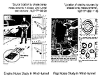
- Fig. 1 illustrates examples of a microphone array measuring method applied to various types of research and development.
- the microphone array method which has recently been developed, several microphones are used for measuring sensors, and the power distribution of a sound source in a space is calculated through the signal processing using a phase difference of measured signal based on distances between a sound source and the measuring sensors. Then, from the distribution map, the location of maximum strength of power can be accepted as a sound source location.
- the measurement accuracy depends on the number of sensors in used. It is known that larger number of sensors give more accurate results.
- C m is a Hermitian conjugate. Accordingly, in order to calculate the beam power map, a grid of virtual sound source is determined at an expected location of that sound source, and beam powers at each grid point are calculated. Then, the calculated beam powers are shown in a space, thereby obtaining a beam power map.
- a beam width and a side-lobe rejection are defined as follows.
- a beam power map can be obtained by the arrangement of microphones used in measurement as shown in Fig. 2 .
- a beam width is defined by a width of a beam in the space at a point corresponding to a level of -3dB from a main lobe corresponding to the position of the sound source.
- a side-lobe rejection is defined by a level difference between side and main lobes, shown in a position at which the sound source does not exist.
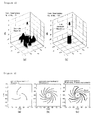
- Fig. 2 illustrates an accuracy difference in a microphone array measuring system depending on the number of sensors used. 31 sensors are used in Fig. 2(a) , and 121 sensors are used in Fig. 2(b) . As shown in Fig. 2 , it can be seen that the performance is improved as the number of sensors used is increased.
- a large number of sensors are required in the conventional method.
- the noise signal is attenuated more by summing up the measured signals, and therefore, performance is improved.
- Sound signals at different location can be measured by moving microphone array with a small number of sensors.
- a beam power map requires simultaneously measured signals form all the sensors being used. This is because a phase difference between the respective measured signals, i.e., a difference of times at which a sound signal reaches the respective sensors, is applied to the beamforming method.
- JP 58 162878 A which serves as basis for the preamble of the independent claims, discloses a radio wave device in which an antenna rotates mechanically and simultaneously forms several beams.
- An object of the present invention is to provide an enhanced sound source localization system and method by using a movable microphone array, wherein a sound source is measured by moving a limited number of microphones, and a signal processing method capable of synchronizing the microphones, so that measurement accuracy can be improved. More specifically, the present invention provides an enhanced sound source localization system and method by using a movable microphone array, wherein one fixed sensor is used, and sound data is obtained at a larger number of measuring points by allowing the other sensors to be moved, so that independently measured signals can be corrected as simultaneously measured signals by applying a synchronizing method using a signal of the fixed sensor.
- an enhanced sound source localization system by using a microphone array beamforming method, which includes: a fixed sensor measuring a sound at a fixed point; a plurality of movable sensors spaced apart from the fixed sensor at a predetermined distance to measure the sound at a plurality of measuring points while moving along a predetermined path about the fixed sensor; and an analyzer receiving sound data measured from the fixed sensor and the movable sensors to perform data analysis, wherein a measured result is obtained by synchronizing the sound data measured from the plurality of movable sensors with the sound data measured from the fixed sensor.
- an enhanced sound source localization method by using the aforementioned sound source localization system, which includes the steps of: a) the analyzer obtaining an ensemble averaged cross spectrum matrix by using sound data measured from the one fixed sensor and the plurality of movable sensors; b) the analyzer repeating a predetermined times (K) an operation of moving the movable sensors to new positions, re-measuring sound data and obtaining an ensemble averaged cross spectrum matrix ( ⁇ A i,j,k >) using the sound data; c) the analyzer correcting a difference of phases in the ensemble averaged cross spectrum matrix ( ⁇ A i,j,k >), thereby obtaining a synchronized cross spectrum matrix ( ⁇ A' i,j,k >); d) the analyzer rearranging the synchronized cross spectrum matrix ( ⁇ A' i,j,k >) as a cross spectrum matrix ( ⁇ A " a,b >) at independent positions; e) the analyzer obtaining unknown terms in the cross spectrum matrix
- i and j denote sensor numbers and are variables each having an integer between 1 to N when assuming that the total number of the fixed sensor and the plurality of movable sensors is N
- k denotes a measuring time and is a variable having an integer between 1 to K .
- measurement performance is determined by the number of high-priced measuring sensors, i.e., microphones when a sound source is measured using the conventional microphone array beamforming method, it is required to increase the number of measuring sensors for the purpose of high measurement performance.
- a sound source is measured by moving a limited number of microphones, so that measurement accuracy can be improved.
- a sound source cannot be measured by moving sensors.
- a sound source is measured by moving microphones, and a signal processing method capable of synchronizing the microphones is applied, thereby obtaining measurement results.
- the number of sensors required to evaluate measured values in a range of desired measurement accuracy can be considerably decreased, and therefore, measuring cost can be remarkably saved.
- the same measurement accuracy as obtained using a plurality of high-priced sensors can be obtained only using a limited number of sensors.
- the performance of the measuring method of the present invention was compared with that of the conventional measuring method through simulation using a numerical method.
- Fig. 3 illustrates arrangements of sensors in verification through numerical simulation.
- Fig. 3(a) illustrates an arrangement of 31 sensors for measuring using the conventional beamforming method as shown in Fig. 2(a).
- Fig. 3(b) illustrates an arrangement of 121 sensors for measuring using the conventional beamforming method as shown in Fig. 2(b).
- Fig. 3(c) illustrates an arrangement of movable 31 sensors for measuring using the measuring method of the present invention.
- Fig. 4 illustrates numerical simulation results of beam power maps for the respective measuring methods of Fig. 3 .
- Fig. 4 it can be seen that side-lobe rejections are remarkably improved as the number of sensors used is increased.
- 31 microphones are substantially used.
- the measuring method of the present invention has a result almost similar to that when 121 sensors are used in the conventional measuring method.
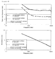
- Fig. 5 illustrates graphs for comparison of performance characteristics in accordance with frequencies for the respective measuring methods, in which beam widths and side-lobe rejections are numerically compared for the purpose of numerical comparison of the aforementioned performance improvement.
- the measured result of the present invention has performance close to that using 121 sensors in the conventional measuring method, even though only 31 sensors are used in the measuring method of the present invention.
- the measuring method of the present invention using a movable microphone array When the measuring method of the present invention using a movable microphone array is applied, the same measurement accuracy as obtained using a plurality of sensors can be obtained only using a small number of sensors, and measurement can be performed at a low cost. Accordingly, it is expected that environmental sound can be reduced as application of a method for reducing sound is extended. Further, the measuring method of the present invention can be extended to various fields through modification of a steering vector in accordance with measurement conditions. Furthermore, the measuring method of the present invention can be applied to localization of a sound source transmitted in the water in addition to a sound source transmitted in the air.
Landscapes
- Engineering & Computer Science (AREA)
- Physics & Mathematics (AREA)
- Health & Medical Sciences (AREA)
- Acoustics & Sound (AREA)
- Computational Linguistics (AREA)
- Audiology, Speech & Language Pathology (AREA)
- Human Computer Interaction (AREA)
- Multimedia (AREA)
- Signal Processing (AREA)
- Quality & Reliability (AREA)
- General Physics & Mathematics (AREA)
- General Health & Medical Sciences (AREA)
- Otolaryngology (AREA)
- Remote Sensing (AREA)
- Radar, Positioning & Navigation (AREA)
- Spectroscopy & Molecular Physics (AREA)
- Measurement Of Velocity Or Position Using Acoustic Or Ultrasonic Waves (AREA)
- Circuit For Audible Band Transducer (AREA)
- Measurement Of Mechanical Vibrations Or Ultrasonic Waves (AREA)
Claims (5)
- Verbessertes Schallquellenortungssystem, wobei das System umfasst:einen stationären Sensor, der Schall an einem feststehenden Punkt misst;eine Mehrzahl beweglicher Sensoren, die von dem stationären Sensor in einem vorherbestimmten Abstand beabstandet sind, um den Schall an einer Mehrzahl von Messpunkten zu messen, während sie sich entlang eines vorherbestimmten Weges um den stationären Sensor bewegen; undeine Analyseeinrichtung, die Schalldaten empfängt, die von dem stationären Sensor und den beweglichen Sensoren gemessen werden, um eine Datenanalyse durchzuführen, wobei ein Messergebnis durch eine Synchronisierung der von der Mehrzahl von beweglichen Sensoren gemessenen Schalldaten mit den von dem stationären Sensor gemessenen Schalldaten ermittelt wird,dadurch gekennzeichnet,dass die Analyseeinrichtung eingerichtet ist,a) um eine Ensemble-gemittelte Kreuzspektrums-Matrix unter Verwendung von Schalldaten, die von dem einen stationären Sensor und der Mehrzahl von beweglichen Sensoren gemessen werden, zu erhalten;b) um eine vorherbestimmte Anzahl (K) von Wiederholungen eines Vorgangs eines Bewegens der beweglichen Sensoren zu neuen Positionen, eines erneuten Messens von Schalldaten und eines Erhaltens einer Ensemble-gemittelten Kreuzspektrums-Matrix (<Ai,j,k >) unter Verwendung der Schalldaten auszuführen;c) um eine Differenz von Phasen in der Ensemble-gemittelten Kreuzspektrums-Matrix (<Ai,j,k >) zu korrigieren, wodurch eine synchronisierte Kreuzspektrums-Matrix (<A'i,j,k >) erhalten wird;d) um die synchronisierte Kreuzspektrums-Matrix (<A'i,i,k >) als eine Kreuzspektrums-Matrix (<A"a,b >) an unabhängigen Positionen umzuordnen;e) um unbekannte Ausdrücke in der Kreuzspektrums-Matrix (<A"a,b >) an unabhängigen Positionen unter Verwendung von Eigenschaften der Kreuzspektrums-Matrix zu erhalten; undf) um eine synchronisierte Strahlleistung (b"m) unter Verwendung der Kreuzspektrums-Matrix (<A"a,b >) an unabhängigen Positionen und einer synchronisierten Steering-Vektor-Matrix

- Verbessertes Schallquellenortungsverfahren und Verwendung eines Schallquellenortungssystems, welches einen stationären Sensor, der Schall an einem feststehenden Punkt misst, eine Mehrzahl beweglicher Sensoren, die von dem stationären Sensor in einem vorherbestimmten Abstand beabstandet sind, um den Schall an einer Mehrzahl von Messpunkten zu messen, während sie sich entlang eines vorherbestimmten Weges um den stationären Sensor bewegen, und eine Analyseeinrichtung umfasst, die Schalldaten empfängt, die von dem stationären Sensor und den beweglichen Sensoren gemessen werden, um eine Datenanalyse durchzuführen, wobei ein Messergebnis durch eine Synchronisierung der von der Mehrzahl von beweglichen Sensoren gemessenen Schalldaten mit den von dem stationären Sensor gemessenen Schalldaten ermittelt wird,
dadurch gekennzeichnet,
dass das Verfahren die Schritte umfasst:a) Erhalten einer Ensemble-gemittelte Kreuzspektrums-Matrix durch die Analyseeinrichtung unter Verwendung von Schalldaten, die von dem einen stationären Sensor und der Mehrzahl von beweglichen Sensoren gemessen werden;b) Ausführen einer vorherbestimmten Anzahl (K) von Wiederholungen eines Vorgangs eines Bewegens der beweglichen Sensoren zu neuen Positionen, eines erneuten Messens von Schalldaten und eines Erhaltens einer Ensemble-gemittelten Kreuzspektrums-Matrix (<Ai,j,k >) unter Verwendung der Schalldaten durch die Analyseeinrichtung;c) Korrigieren einer Differenz von Phasen in der Ensemble-gemittelten Kreuzspektrums-Matrix (<Ai,j,k >) durch die Analyseeinrichtung, wodurch eine synchronisierte Kreuzspektrums-Matrix (<A'i,j,k >) erhalten wird;d) Umordnen der synchronisierten Kreuzspektrums-Matrix (<A'i,j,k >) als eine Kreuzspektrums-Matrix (<iA"a,b >) an unabhängigen Positionen durch die Analyseeinrichtung;e) Erhalten unbekannter Ausdrücke in der Kreuzspektrums-Matrix (<A"a,b >) an unabhängigen Positionen unter Verwendung von Eigenschaften der Kreuzspektrums-Matrix durch die Analyseeinrichtung; undf) Erhalten einer synchronisierten Strahlleistung (b"m ) durch die Analyseeinrichtung unter Verwendung der Kreuzspektrums-Matrix (<A"a,b >) an unabhängigen Positionen und einer synchronisierten Steering-Vektor-Matrix
- Verfahren nach Anspruch 2, wobei die Analyseeinrichtung in dem Schritt c) die synchronisierte Kreuzspektrums-Matrix unter Verwendung der folgenden Formel erhält;

wobei i und j Sensornummern bezeichnen und Variablen sind, die jeweils einen ganzzahligen Wert von 1 bis N annehmen, wenn man annimmt, dass die Gesamtanzahl des stationären Sensors und der Mehrzahl beweglicher Sensoren N ist, und k eine Messzeit bezeichnet und eine Variable mit einem ganzzahligen Wert von 1 bis K ist. - Verfahren nach Anspruch 2, wobei die Analyseeinrichtung in dem Schritt e) die unbekannten Ausdrücke in der Kreuzspektrums-Matrix (<A"a,b >) an unabhängigen Positionen unter Verwendung der folgenden Gleichung erhält;

- Verfahren nach Anspruch 2, wobei die Analyseeinrichtung in dem Schritt f) die synchronisierte Strahlleistung (b"m) unter Verwendung der folgenden Gleichung erhält;

Applications Claiming Priority (2)
| Application Number | Priority Date | Filing Date | Title |
|---|---|---|---|
| KR1020070102220A KR100921368B1 (ko) | 2007-10-10 | 2007-10-10 | 이동형 마이크로폰 어레이를 이용한 소음원 위치 판별정밀도 개선 시스템 및 방법 |
| PCT/KR2008/005969 WO2009048291A1 (en) | 2007-10-10 | 2008-10-10 | Enhanced sound source localization system and method by using a movable microphone array |
Publications (3)
| Publication Number | Publication Date |
|---|---|
| EP2201564A1 EP2201564A1 (de) | 2010-06-30 |
| EP2201564A4 EP2201564A4 (de) | 2013-03-06 |
| EP2201564B1 true EP2201564B1 (de) | 2014-12-03 |
Family
ID=40549368
Family Applications (1)
| Application Number | Title | Priority Date | Filing Date |
|---|---|---|---|
| EP08837260.2A Active EP2201564B1 (de) | 2007-10-10 | 2008-10-10 | Verbessertes schallquellenortungssystem und verfahren mittels verwendung einer beweglichen mikrofonanordnung |
Country Status (3)
| Country | Link |
|---|---|
| EP (1) | EP2201564B1 (de) |
| KR (1) | KR100921368B1 (de) |
| WO (1) | WO2009048291A1 (de) |
Families Citing this family (11)
| Publication number | Priority date | Publication date | Assignee | Title |
|---|---|---|---|---|
| DE102008029352A1 (de) | 2008-06-20 | 2009-12-31 | Fraunhofer-Gesellschaft zur Förderung der angewandten Forschung e.V. | Vorrichtung, Verfahren und Computerprogramm zum Lokalisieren einer Schallquelle |
| US9351070B2 (en) | 2009-06-30 | 2016-05-24 | Nokia Technologies Oy | Positional disambiguation in spatial audio |
| KR101097296B1 (ko) | 2010-04-30 | 2011-12-22 | 충남대학교산학협력단 | 회전 소음원 측정용 마이크로폰 어레이 시스템 및 상기 마이크로폰 어레이를 이용한 회전 소음원 측정 방법 |
| WO2016034454A1 (en) * | 2014-09-05 | 2016-03-10 | Thomson Licensing | Method and apparatus for enhancing sound sources |
| WO2019178626A1 (de) * | 2018-03-19 | 2019-09-26 | Seven Bel Gmbh | Vorrichtung, system und verfahren zur räumlichen lokalisierung von schallquellen |
| CN111948605B (zh) * | 2020-08-12 | 2021-05-11 | 上海交通大学 | 融合渐开线阵列和fpga的便携式噪声源检测装置 |
| CN112763058A (zh) * | 2021-01-07 | 2021-05-07 | 国网河南省电力公司电力科学研究院 | 一种自定义坐标阵列噪声信号实时数据分析系统及方法 |
| CN113376578A (zh) * | 2021-06-07 | 2021-09-10 | 上海数川数据科技有限公司 | 一种基于到达角度和声音强度匹配的声源定位方法及系统 |
| CN114199368B (zh) * | 2021-11-30 | 2024-04-26 | 北京工商大学 | 一种全频带pp声强自动测量装置和测量方法 |
| CN116577599A (zh) * | 2023-03-28 | 2023-08-11 | 中核检修有限公司 | 一种麦克风和红外热成像联合定位的电缆故障定位方法及系统 |
| CN118549084B (zh) * | 2024-07-30 | 2024-10-08 | 中国空气动力研究与发展中心低速空气动力研究所 | 一种喷流噪声场的测量方法及连续扫描式传声器测量系统 |
Family Cites Families (4)
| Publication number | Priority date | Publication date | Assignee | Title |
|---|---|---|---|---|
| JPS58162878A (ja) * | 1982-03-23 | 1983-09-27 | Nec Corp | 電波装置 |
| DK174558B1 (da) * | 2002-03-15 | 2003-06-02 | Bruel & Kjaer Sound & Vibratio | Stråleformende transducer-antennesystem |
| KR100499124B1 (ko) * | 2002-03-27 | 2005-07-04 | 삼성전자주식회사 | 직교 원형 마이크 어레이 시스템 및 이를 이용한 음원의3차원 방향을 검출하는 방법 |
| KR100493172B1 (ko) * | 2003-03-06 | 2005-06-02 | 삼성전자주식회사 | 마이크로폰 어레이 구조, 이를 이용한 일정한 지향성을갖는 빔 형성방법 및 장치와 음원방향 추정방법 및 장치 |
-
2007
- 2007-10-10 KR KR1020070102220A patent/KR100921368B1/ko active Active
-
2008
- 2008-10-10 WO PCT/KR2008/005969 patent/WO2009048291A1/en not_active Ceased
- 2008-10-10 EP EP08837260.2A patent/EP2201564B1/de active Active
Also Published As
| Publication number | Publication date |
|---|---|
| KR100921368B1 (ko) | 2009-10-14 |
| EP2201564A4 (de) | 2013-03-06 |
| WO2009048291A1 (en) | 2009-04-16 |
| KR20090036919A (ko) | 2009-04-15 |
| EP2201564A1 (de) | 2010-06-30 |
Similar Documents
| Publication | Publication Date | Title |
|---|---|---|
| EP2201564A1 (de) | Verbessertes schallquellenortungssystem und verfahren mittels verwendung einer beweglichen mikrofonanordnung | |
| US10389421B2 (en) | Apparatus for estimating arrival-angle and apparatus for beam-forming | |
| EP2159593B1 (de) | Verfahren und Vorrichtung zum Lokalisieren einer Schallquelle | |
| CN102508213B (zh) | 基于零陷加宽的波束域自适应干扰抑制方法 | |
| EP2098875B1 (de) | Einrichtung und programm zur schätzung der empfangenen feldintensität | |
| US11982761B2 (en) | Method for calibrating a phased array | |
| CN103217211B (zh) | 一种基于合成孔径原理的变电站噪声源分布测量方法 | |
| KR101953697B1 (ko) | 균일 선형 배열 안테나 기반의 가상 수신신호 생성을 이용한 도래각 추정 방법 및 장치 | |
| US10746765B2 (en) | Data processing method and the measurement device | |
| CN104345306B (zh) | 基于Khatri‑Rao子空间的目标波达角估计方法 | |
| Zhang et al. | Order domain beamforming for the acoustic localization of rotating machinery under variable speed working conditions | |
| US10725168B2 (en) | Near-field measurement system and method for obtaining far-field characteristics | |
| CN102957472B (zh) | 稀疏阵列天线系统接收通信信号的方法及装置 | |
| RU2407026C1 (ru) | Способ пеленгации узкополосных радиосигналов кв диапазона | |
| Yang et al. | A fast deconvolution method for multiple sound source localization based on Hilbert curve | |
| CN112710990A (zh) | 适用于任意平面阵列形式的二维无网格压缩波束形成方法 | |
| CN101902755A (zh) | 智能天线模拟方法和装置及广播波束权值获取方法和装置 | |
| CN110850348B (zh) | 一种用于核磁共振多峰激发的形状脉冲编辑及控制方法 | |
| Van De Ven et al. | Stochastic modeling and analysis of gain ripple effects in automotive corner radar antennas | |
| CN103116153B (zh) | 桅杆遮挡时八单元均匀圆阵天线导向矢量构建方法 | |
| Jiang et al. | A new source number estimation method based on the beam eigenvalue | |
| Cousson et al. | Identification of acoustic moving sources in the context of a road vehicle at pass-by | |
| RU2634735C1 (ru) | Способ определения амплитудно-фазового распределения в раскрыве фазированной антенной решетки | |
| CN119469005B (zh) | 定子组装检测方法、装置、设备及存储介质 | |
| Nicolas | In situ array antenna diagnosis using microwave circular holography |
Legal Events
| Date | Code | Title | Description |
|---|---|---|---|
| PUAI | Public reference made under article 153(3) epc to a published international application that has entered the european phase |
Free format text: ORIGINAL CODE: 0009012 |
|
| 17P | Request for examination filed |
Effective date: 20100409 |
|
| AK | Designated contracting states |
Kind code of ref document: A1 Designated state(s): AT BE BG CH CY CZ DE DK EE ES FI FR GB GR HR HU IE IS IT LI LT LU LV MC MT NL NO PL PT RO SE SI SK TR |
|
| AX | Request for extension of the european patent |
Extension state: AL BA MK RS |
|
| DAX | Request for extension of the european patent (deleted) | ||
| A4 | Supplementary search report drawn up and despatched |
Effective date: 20130206 |
|
| RIC1 | Information provided on ipc code assigned before grant |
Ipc: H04R 3/00 20060101ALI20130131BHEP Ipc: G10L 15/20 20060101AFI20130131BHEP Ipc: G01S 3/809 20060101ALI20130131BHEP Ipc: G10L 21/02 20130101ALI20130131BHEP |
|
| GRAP | Despatch of communication of intention to grant a patent |
Free format text: ORIGINAL CODE: EPIDOSNIGR1 |
|
| RIC1 | Information provided on ipc code assigned before grant |
Ipc: H04R 3/00 20060101ALI20140422BHEP Ipc: G10L 15/20 20060101AFI20140422BHEP Ipc: G01S 3/809 20060101ALI20140422BHEP Ipc: G10L 21/02 20130101ALI20140422BHEP |
|
| INTG | Intention to grant announced |
Effective date: 20140513 |
|
| GRAS | Grant fee paid |
Free format text: ORIGINAL CODE: EPIDOSNIGR3 |
|
| GRAA | (expected) grant |
Free format text: ORIGINAL CODE: 0009210 |
|
| AK | Designated contracting states |
Kind code of ref document: B1 Designated state(s): AT BE BG CH CY CZ DE DK EE ES FI FR GB GR HR HU IE IS IT LI LT LU LV MC MT NL NO PL PT RO SE SI SK TR |
|
| RAP1 | Party data changed (applicant data changed or rights of an application transferred) |
Owner name: THE INDUSTRY & ACADEMIC COOPERATION IN CHUNGNAM NA |
|
| REG | Reference to a national code |
Ref country code: GB Ref legal event code: FG4D |
|
| REG | Reference to a national code |
Ref country code: AT Ref legal event code: REF Ref document number: 699761 Country of ref document: AT Kind code of ref document: T Effective date: 20141215 Ref country code: CH Ref legal event code: EP |
|
| REG | Reference to a national code |
Ref country code: IE Ref legal event code: FG4D |
|
| REG | Reference to a national code |
Ref country code: DE Ref legal event code: R096 Ref document number: 602008035714 Country of ref document: DE Effective date: 20150115 |
|
| REG | Reference to a national code |
Ref country code: NL Ref legal event code: VDEP Effective date: 20141203 |
|
| REG | Reference to a national code |
Ref country code: AT Ref legal event code: MK05 Ref document number: 699761 Country of ref document: AT Kind code of ref document: T Effective date: 20141203 |
|
| PG25 | Lapsed in a contracting state [announced via postgrant information from national office to epo] |
Ref country code: ES Free format text: LAPSE BECAUSE OF FAILURE TO SUBMIT A TRANSLATION OF THE DESCRIPTION OR TO PAY THE FEE WITHIN THE PRESCRIBED TIME-LIMIT Effective date: 20141203 Ref country code: NO Free format text: LAPSE BECAUSE OF FAILURE TO SUBMIT A TRANSLATION OF THE DESCRIPTION OR TO PAY THE FEE WITHIN THE PRESCRIBED TIME-LIMIT Effective date: 20150303 Ref country code: NL Free format text: LAPSE BECAUSE OF FAILURE TO SUBMIT A TRANSLATION OF THE DESCRIPTION OR TO PAY THE FEE WITHIN THE PRESCRIBED TIME-LIMIT Effective date: 20141203 Ref country code: LT Free format text: LAPSE BECAUSE OF FAILURE TO SUBMIT A TRANSLATION OF THE DESCRIPTION OR TO PAY THE FEE WITHIN THE PRESCRIBED TIME-LIMIT Effective date: 20141203 Ref country code: FI Free format text: LAPSE BECAUSE OF FAILURE TO SUBMIT A TRANSLATION OF THE DESCRIPTION OR TO PAY THE FEE WITHIN THE PRESCRIBED TIME-LIMIT Effective date: 20141203 |
|
| REG | Reference to a national code |
Ref country code: LT Ref legal event code: MG4D |
|
| PG25 | Lapsed in a contracting state [announced via postgrant information from national office to epo] |
Ref country code: GR Free format text: LAPSE BECAUSE OF FAILURE TO SUBMIT A TRANSLATION OF THE DESCRIPTION OR TO PAY THE FEE WITHIN THE PRESCRIBED TIME-LIMIT Effective date: 20150304 Ref country code: AT Free format text: LAPSE BECAUSE OF FAILURE TO SUBMIT A TRANSLATION OF THE DESCRIPTION OR TO PAY THE FEE WITHIN THE PRESCRIBED TIME-LIMIT Effective date: 20141203 Ref country code: LV Free format text: LAPSE BECAUSE OF FAILURE TO SUBMIT A TRANSLATION OF THE DESCRIPTION OR TO PAY THE FEE WITHIN THE PRESCRIBED TIME-LIMIT Effective date: 20141203 Ref country code: CY Free format text: LAPSE BECAUSE OF FAILURE TO SUBMIT A TRANSLATION OF THE DESCRIPTION OR TO PAY THE FEE WITHIN THE PRESCRIBED TIME-LIMIT Effective date: 20141203 Ref country code: HR Free format text: LAPSE BECAUSE OF FAILURE TO SUBMIT A TRANSLATION OF THE DESCRIPTION OR TO PAY THE FEE WITHIN THE PRESCRIBED TIME-LIMIT Effective date: 20141203 Ref country code: SE Free format text: LAPSE BECAUSE OF FAILURE TO SUBMIT A TRANSLATION OF THE DESCRIPTION OR TO PAY THE FEE WITHIN THE PRESCRIBED TIME-LIMIT Effective date: 20141203 |
|
| PG25 | Lapsed in a contracting state [announced via postgrant information from national office to epo] |
Ref country code: SK Free format text: LAPSE BECAUSE OF FAILURE TO SUBMIT A TRANSLATION OF THE DESCRIPTION OR TO PAY THE FEE WITHIN THE PRESCRIBED TIME-LIMIT Effective date: 20141203 Ref country code: EE Free format text: LAPSE BECAUSE OF FAILURE TO SUBMIT A TRANSLATION OF THE DESCRIPTION OR TO PAY THE FEE WITHIN THE PRESCRIBED TIME-LIMIT Effective date: 20141203 Ref country code: PT Free format text: LAPSE BECAUSE OF FAILURE TO SUBMIT A TRANSLATION OF THE DESCRIPTION OR TO PAY THE FEE WITHIN THE PRESCRIBED TIME-LIMIT Effective date: 20150403 Ref country code: CZ Free format text: LAPSE BECAUSE OF FAILURE TO SUBMIT A TRANSLATION OF THE DESCRIPTION OR TO PAY THE FEE WITHIN THE PRESCRIBED TIME-LIMIT Effective date: 20141203 Ref country code: RO Free format text: LAPSE BECAUSE OF FAILURE TO SUBMIT A TRANSLATION OF THE DESCRIPTION OR TO PAY THE FEE WITHIN THE PRESCRIBED TIME-LIMIT Effective date: 20141203 |
|
| PG25 | Lapsed in a contracting state [announced via postgrant information from national office to epo] |
Ref country code: IS Free format text: LAPSE BECAUSE OF FAILURE TO SUBMIT A TRANSLATION OF THE DESCRIPTION OR TO PAY THE FEE WITHIN THE PRESCRIBED TIME-LIMIT Effective date: 20150403 Ref country code: PL Free format text: LAPSE BECAUSE OF FAILURE TO SUBMIT A TRANSLATION OF THE DESCRIPTION OR TO PAY THE FEE WITHIN THE PRESCRIBED TIME-LIMIT Effective date: 20141203 |
|
| REG | Reference to a national code |
Ref country code: DE Ref legal event code: R097 Ref document number: 602008035714 Country of ref document: DE |
|
| PLBE | No opposition filed within time limit |
Free format text: ORIGINAL CODE: 0009261 |
|
| STAA | Information on the status of an ep patent application or granted ep patent |
Free format text: STATUS: NO OPPOSITION FILED WITHIN TIME LIMIT |
|
| PG25 | Lapsed in a contracting state [announced via postgrant information from national office to epo] |
Ref country code: DK Free format text: LAPSE BECAUSE OF FAILURE TO SUBMIT A TRANSLATION OF THE DESCRIPTION OR TO PAY THE FEE WITHIN THE PRESCRIBED TIME-LIMIT Effective date: 20141203 |
|
| 26N | No opposition filed |
Effective date: 20150904 |
|
| PG25 | Lapsed in a contracting state [announced via postgrant information from national office to epo] |
Ref country code: IT Free format text: LAPSE BECAUSE OF FAILURE TO SUBMIT A TRANSLATION OF THE DESCRIPTION OR TO PAY THE FEE WITHIN THE PRESCRIBED TIME-LIMIT Effective date: 20141203 |
|
| PG25 | Lapsed in a contracting state [announced via postgrant information from national office to epo] |
Ref country code: SI Free format text: LAPSE BECAUSE OF FAILURE TO SUBMIT A TRANSLATION OF THE DESCRIPTION OR TO PAY THE FEE WITHIN THE PRESCRIBED TIME-LIMIT Effective date: 20141203 |
|
| PG25 | Lapsed in a contracting state [announced via postgrant information from national office to epo] |
Ref country code: LU Free format text: LAPSE BECAUSE OF FAILURE TO SUBMIT A TRANSLATION OF THE DESCRIPTION OR TO PAY THE FEE WITHIN THE PRESCRIBED TIME-LIMIT Effective date: 20151010 Ref country code: BE Free format text: LAPSE BECAUSE OF FAILURE TO SUBMIT A TRANSLATION OF THE DESCRIPTION OR TO PAY THE FEE WITHIN THE PRESCRIBED TIME-LIMIT Effective date: 20141203 |
|
| REG | Reference to a national code |
Ref country code: CH Ref legal event code: PL |
|
| GBPC | Gb: european patent ceased through non-payment of renewal fee |
Effective date: 20151010 |
|
| PG25 | Lapsed in a contracting state [announced via postgrant information from national office to epo] |
Ref country code: MC Free format text: LAPSE BECAUSE OF FAILURE TO SUBMIT A TRANSLATION OF THE DESCRIPTION OR TO PAY THE FEE WITHIN THE PRESCRIBED TIME-LIMIT Effective date: 20141203 |
|
| REG | Reference to a national code |
Ref country code: IE Ref legal event code: MM4A |
|
| PG25 | Lapsed in a contracting state [announced via postgrant information from national office to epo] |
Ref country code: GB Free format text: LAPSE BECAUSE OF NON-PAYMENT OF DUE FEES Effective date: 20151010 Ref country code: CH Free format text: LAPSE BECAUSE OF NON-PAYMENT OF DUE FEES Effective date: 20151031 Ref country code: LI Free format text: LAPSE BECAUSE OF NON-PAYMENT OF DUE FEES Effective date: 20151031 |
|
| REG | Reference to a national code |
Ref country code: FR Ref legal event code: ST Effective date: 20160630 |
|
| PG25 | Lapsed in a contracting state [announced via postgrant information from national office to epo] |
Ref country code: FR Free format text: LAPSE BECAUSE OF NON-PAYMENT OF DUE FEES Effective date: 20151102 |
|
| PG25 | Lapsed in a contracting state [announced via postgrant information from national office to epo] |
Ref country code: IE Free format text: LAPSE BECAUSE OF NON-PAYMENT OF DUE FEES Effective date: 20151010 |
|
| PG25 | Lapsed in a contracting state [announced via postgrant information from national office to epo] |
Ref country code: BG Free format text: LAPSE BECAUSE OF FAILURE TO SUBMIT A TRANSLATION OF THE DESCRIPTION OR TO PAY THE FEE WITHIN THE PRESCRIBED TIME-LIMIT Effective date: 20141203 Ref country code: HU Free format text: LAPSE BECAUSE OF FAILURE TO SUBMIT A TRANSLATION OF THE DESCRIPTION OR TO PAY THE FEE WITHIN THE PRESCRIBED TIME-LIMIT; INVALID AB INITIO Effective date: 20081010 |
|
| PG25 | Lapsed in a contracting state [announced via postgrant information from national office to epo] |
Ref country code: TR Free format text: LAPSE BECAUSE OF FAILURE TO SUBMIT A TRANSLATION OF THE DESCRIPTION OR TO PAY THE FEE WITHIN THE PRESCRIBED TIME-LIMIT Effective date: 20141203 Ref country code: MT Free format text: LAPSE BECAUSE OF FAILURE TO SUBMIT A TRANSLATION OF THE DESCRIPTION OR TO PAY THE FEE WITHIN THE PRESCRIBED TIME-LIMIT Effective date: 20141203 |
|
| PGFP | Annual fee paid to national office [announced via postgrant information from national office to epo] |
Ref country code: DE Payment date: 20250922 Year of fee payment: 18 |