EP2201590B1 - Einbaulampe mit kabel, insbesondere zur flugplatzbefeuerung - Google Patents
Einbaulampe mit kabel, insbesondere zur flugplatzbefeuerung Download PDFInfo
- Publication number
- EP2201590B1 EP2201590B1 EP07821493A EP07821493A EP2201590B1 EP 2201590 B1 EP2201590 B1 EP 2201590B1 EP 07821493 A EP07821493 A EP 07821493A EP 07821493 A EP07821493 A EP 07821493A EP 2201590 B1 EP2201590 B1 EP 2201590B1
- Authority
- EP
- European Patent Office
- Prior art keywords
- lamp
- insulator
- small tube
- metal sleeve
- tube
- Prior art date
- Legal status (The legal status is an assumption and is not a legal conclusion. Google has not performed a legal analysis and makes no representation as to the accuracy of the status listed.)
- Not-in-force
Links
- 239000012212 insulator Substances 0.000 claims abstract description 52
- 239000011521 glass Substances 0.000 claims abstract description 38
- 229910052751 metal Inorganic materials 0.000 claims description 59
- 239000002184 metal Substances 0.000 claims description 59
- 238000002788 crimping Methods 0.000 claims description 22
- 238000000034 method Methods 0.000 claims description 11
- 238000004519 manufacturing process Methods 0.000 claims description 7
- 229910052736 halogen Inorganic materials 0.000 claims description 4
- 150000002367 halogens Chemical class 0.000 claims description 4
- 239000005357 flat glass Substances 0.000 claims 1
- 230000017525 heat dissipation Effects 0.000 description 5
- 239000000919 ceramic Substances 0.000 description 4
- 238000009434 installation Methods 0.000 description 4
- ZOKXTWBITQBERF-UHFFFAOYSA-N Molybdenum Chemical compound [Mo] ZOKXTWBITQBERF-UHFFFAOYSA-N 0.000 description 2
- 230000004323 axial length Effects 0.000 description 2
- 239000011888 foil Substances 0.000 description 2
- 238000003780 insertion Methods 0.000 description 2
- 230000037431 insertion Effects 0.000 description 2
- 239000000463 material Substances 0.000 description 2
- 229910052750 molybdenum Inorganic materials 0.000 description 2
- 239000011733 molybdenum Substances 0.000 description 2
- 230000002411 adverse Effects 0.000 description 1
- 238000010276 construction Methods 0.000 description 1
- 238000005520 cutting process Methods 0.000 description 1
- 230000002950 deficient Effects 0.000 description 1
- 230000001419 dependent effect Effects 0.000 description 1
- 230000000694 effects Effects 0.000 description 1
- 238000010438 heat treatment Methods 0.000 description 1
- 238000005286 illumination Methods 0.000 description 1
- 230000014759 maintenance of location Effects 0.000 description 1
- 230000013011 mating Effects 0.000 description 1
- 238000002844 melting Methods 0.000 description 1
- 230000008018 melting Effects 0.000 description 1
- 150000002739 metals Chemical class 0.000 description 1
- 230000003647 oxidation Effects 0.000 description 1
- 238000007254 oxidation reaction Methods 0.000 description 1
- 238000003825 pressing Methods 0.000 description 1
- 238000004080 punching Methods 0.000 description 1
- 238000000926 separation method Methods 0.000 description 1
- IHQKEDIOMGYHEB-UHFFFAOYSA-M sodium dimethylarsinate Chemical class [Na+].C[As](C)([O-])=O IHQKEDIOMGYHEB-UHFFFAOYSA-M 0.000 description 1
- 229910000679 solder Inorganic materials 0.000 description 1
- 238000003466 welding Methods 0.000 description 1
Images



Classifications
-
- H—ELECTRICITY
- H01—ELECTRIC ELEMENTS
- H01J—ELECTRIC DISCHARGE TUBES OR DISCHARGE LAMPS
- H01J5/00—Details relating to vessels or to leading-in conductors common to two or more basic types of discharge tubes or lamps
- H01J5/50—Means forming part of the tube or lamps for the purpose of providing electrical connection to it
- H01J5/54—Means forming part of the tube or lamps for the purpose of providing electrical connection to it supported by a separate part, e.g. base
- H01J5/62—Connection of wires protruding from the vessel to connectors carried by the separate part
-
- F—MECHANICAL ENGINEERING; LIGHTING; HEATING; WEAPONS; BLASTING
- F21—LIGHTING
- F21V—FUNCTIONAL FEATURES OR DETAILS OF LIGHTING DEVICES OR SYSTEMS THEREOF; STRUCTURAL COMBINATIONS OF LIGHTING DEVICES WITH OTHER ARTICLES, NOT OTHERWISE PROVIDED FOR
- F21V19/00—Fastening of light sources or lamp holders
- F21V19/0005—Fastening of light sources or lamp holders of sources having contact pins, wires or blades, e.g. pinch sealed lamp
-
- F—MECHANICAL ENGINEERING; LIGHTING; HEATING; WEAPONS; BLASTING
- F21—LIGHTING
- F21W—INDEXING SCHEME ASSOCIATED WITH SUBCLASSES F21K, F21L, F21S and F21V, RELATING TO USES OR APPLICATIONS OF LIGHTING DEVICES OR SYSTEMS
- F21W2111/00—Use or application of lighting devices or systems for signalling, marking or indicating, not provided for in codes F21W2102/00 – F21W2107/00
-
- F—MECHANICAL ENGINEERING; LIGHTING; HEATING; WEAPONS; BLASTING
- F21—LIGHTING
- F21W—INDEXING SCHEME ASSOCIATED WITH SUBCLASSES F21K, F21L, F21S and F21V, RELATING TO USES OR APPLICATIONS OF LIGHTING DEVICES OR SYSTEMS
- F21W2111/00—Use or application of lighting devices or systems for signalling, marking or indicating, not provided for in codes F21W2102/00 – F21W2107/00
- F21W2111/06—Use or application of lighting devices or systems for signalling, marking or indicating, not provided for in codes F21W2102/00 – F21W2107/00 for aircraft runways or the like
-
- H—ELECTRICITY
- H01—ELECTRIC ELEMENTS
- H01R—ELECTRICALLY-CONDUCTIVE CONNECTIONS; STRUCTURAL ASSOCIATIONS OF A PLURALITY OF MUTUALLY-INSULATED ELECTRICAL CONNECTING ELEMENTS; COUPLING DEVICES; CURRENT COLLECTORS
- H01R2201/00—Connectors or connections adapted for particular applications
- H01R2201/08—Connectors or connections adapted for particular applications for halogen lamps
-
- H—ELECTRICITY
- H01—ELECTRIC ELEMENTS
- H01R—ELECTRICALLY-CONDUCTIVE CONNECTIONS; STRUCTURAL ASSOCIATIONS OF A PLURALITY OF MUTUALLY-INSULATED ELECTRICAL CONNECTING ELEMENTS; COUPLING DEVICES; CURRENT COLLECTORS
- H01R4/00—Electrically-conductive connections between two or more conductive members in direct contact, i.e. touching one another; Means for effecting or maintaining such contact; Electrically-conductive connections having two or more spaced connecting locations for conductors and using contact members penetrating insulation
- H01R4/10—Electrically-conductive connections between two or more conductive members in direct contact, i.e. touching one another; Means for effecting or maintaining such contact; Electrically-conductive connections having two or more spaced connecting locations for conductors and using contact members penetrating insulation effected solely by twisting, wrapping, bending, crimping, or other permanent deformation
- H01R4/18—Electrically-conductive connections between two or more conductive members in direct contact, i.e. touching one another; Means for effecting or maintaining such contact; Electrically-conductive connections having two or more spaced connecting locations for conductors and using contact members penetrating insulation effected solely by twisting, wrapping, bending, crimping, or other permanent deformation by crimping
Definitions
- the invention relates to a lamp with attached cable, in particular for installation in a reflector housing for the illumination and marking of aircraft taxiways.
- halogen incandescent lamps are preferably used, the light of which is bundled and directed by means of a reflector. It is also conceivable, however, the use of high pressure discharge lamps. In the following, for the sake of simplicity, halogen incandescent lamps with incandescent filament are assumed, but also high-pressure discharge lamps with arc should be included.
- the font DE 198 42 794 A1 discloses a reflector lamp comprising a lamp vessel having outwardly projecting external power leads therefrom.
- the lamp vessel is held in the reflector neck, which is provided with a centering disc.
- the power supply of the lamp vessel are crimped within the reflector neck with protruding from the reflector neck contact pins.
- the object of the present invention is to provide an improved lamp of the type described and a corresponding manufacturing method.
- the problem is solved by a lamp with a glass container with the end of which has protruding pins and is supported in a socket with an insulator, the socket receiving a position adjusting flange (18) and wherein the insulator (2, 6) comprises in at least one through hole a metallic tube (1) between a contact pin (16) the lamp vessel (14) and a connection cable (4) to be supplied with current, with which tube (1) the contact pin (16) is crimped and the connection cable (4) is connected, characterized in that the insulator is surrounded by a lamp-side open metal sleeve, and by a corresponding manufacturing method according to claim 13.
- the inventors have recognized that by crimping in the socket lamps with attached cable can be particularly easily and reliably produced. Crimp connections can be compared to welding or solder joints without heating and control of melting metals and thus easier and less expensive to implement.
- the idea underlying the invention further includes, by means of at least one metal tube to allow a Crimpucunsan gleich of pins on connecting cables.
- the at least one metal tube is crimped glass vessel side with the corresponding contact pin and connected on the opposite side with a current-carrying cable.
- the cable can be welded to the tube, for example, soldered or particularly advantageously also crimped.
- the shape of the necessary for crimping additional component as a tube, since by simply mating with the pin already glass vessel and cable can be provisionally supported in final position and only need to be crimped to produce a permanent connection. Also, the shape of a tube is good for crimping.
- tube is to be understood from this context: it does not necessarily have to be a circumferentially completely closed tube. A remaining slot would not hurt as long as the contact pin can be inserted and held. It may also be sufficient to provide a suitable for insertion and retention of the contact pin cross-sectional profile of the tube along its axial length only in places. Particularly preferred is a simple tube with a constant over the axial length circular ring cross section.
- the filament (or an electrode) and the power supply holds.
- the end of the lamp glass vessel is formed as a flat end, in particular glass crushing.
- the outside of the pinch pin-shaped power supply then often have molybdenum foils inside the pinch.
- the base receptacle with the lamp glass vessel may preferably be fixed in a reflector as known by means of a position adjustment flange.
- the flange is preferably mounted on a metal sleeve, wherein the position of the flange is based on the ideal position of the light-generating filament within the reflector.
- At least one of the contact pins must be electrically insulated, in particular with respect to a base receptacle with metal parts, as mentioned above.
- the other contact pin could also be connected to the metal sleeve or other conductive environment parts.
- the insulator may consist of a glass or ceramic tube in the minimum case, for example.
- the insulator is a ceramic cuboid with the contact pin and the metal tube receiving through bore. More preferably, there are two holes for both pins in the ceramic cuboid so that both pins are isolated from each other and from the environment.
- connection cable In the electrical connection of the or the connection cable to the one or more metal tube can be provided for expansion of tube and / or cable, so that the tube can not be pulled out to the lamp glass vessel out of the insulator.
- a backup against unintentional tearing out of the lamp vessel from the base receptacle can be achieved.
- connection cable in the metal tube.
- the metal sleeve is preferably applied by means of inwardly bent metal tabs at the flat end.
- the metal tabs can also snap into notches or behind grooves in or on the flat end and additionally fix the lamp glass vessel in the base receptacle. This results in a particularly effective protection against unintentional separation.
- the tabs acting on the pinch serve to improve the dissipation of the heat generated in the lamp.
- the tabs protruding into the interior of the metal sleeve and mentioned above can be realized particularly simply by cuts in the metal sheet of the metal sleeve.
- Additional opening windows in the area of the tabs result in an informal manner when the tabs defining the tabs are larger than the tabs themselves and comprise a continuous area.
- the cuts can be made for example with punching or cutting tools.
- the metal tube receiving isolator can be constructed in two parts. For example, a first part can accommodate the tubes and a second part contain holes through which the connection cables are fed to the tubes. This facilitates the assembly or connection of connecting cable and tube and makes it possible to strip the current-carrying cable over a longer distance, for example, to prevent heat-related damage to the insulating sheathing of the cable.
- the crimping of the contact pin and metal tube can still be performed even if the tubes are already mounted in the base receptacle.
- there are lateral recesses in the insulator, which are connected allow access to the crimping after insertion of the contact pins with the opening windows of the metal sleeve.
- the step of crimping the tube and pin can also take place prior to assembly.
- the following sequence can be advantageously followed when assembling the lamp: First, the (or the metal tube inserted into the through hole of the glass vessel side first insulator part, then (or) the connection cable crimping (or) the tube, deforming the tube-side tube ends to prevent tube removal, then pulling the second insulator piece over the lead (s) so that the free-standing tube-side tube ends are trapped by the insulator of tube, insulator and cables is now inserted into the metal sleeve, and fixed in this by punctiform impressions of the metal sleeve wall on the one hand and by folding a corresponding projection on the sleeve plate on the other hand in the metal sleeve tion of the insulator in the metal sleeve can be accomplished otherwise in principle, for. B. by screwing.
- FIG. 1 shows two metal tubes 1, which are mounted in a first insulator part 2 made of ceramic.
- This first insulator part 2 has at the tube ends, which face the lamp glass vessel in the installed state, material recesses 3, which allow access to crimping of the tubes 1 in a later method step.
- the tubes 1 have at their glass-vessel-side end of a widening 20, the tubes against a cable-side pulling out or falling out of the first insulator part secures.
- the extent of the first insulator part in the direction of the tube axis is dimensioned such that a sufficient part of the tubes for crimping with the cables protrudes from the insulator part when the flare 20 of the tubes is flush with the corresponding surface of the first insulator part.
- FIG. 2 shows the connection of two connecting cables 4 to the tubes 1. At its tube-side end of the cables 4 are stripped and crimped with the tubes. The crimping 5 squeezes the tubes such that withdrawal of the tubes from the first insulator part is no longer possible (not shown).
- the tubes are already supported by the first insulator part, which simplifies the crimping with the cable ends.
- FIG. 3 shows a second insulator part 6, which connects directly to the first insulator part 2 and the crimping of tube 1 and connecting cables 4 completely surrounds. Also shown are cable lugs 7, which are exemplary of a connection of the cable ends with a power supply.
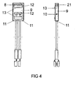
- a metal sleeve 9 surrounds the assembly of first insulator part, second insulator part and metal tube.
- This assembly is fixed in the metal sleeve by a punctiform impression 10 of the metal shell and inwardly bent sheet metal edges 11.
- the metal sleeve has on the broad sides of metal tabs 8, which later attack heat dissipation at the glass pinch and this possibly also by Schuschnappen can fix in corresponding recesses and grooves in the metal sleeve 9.
- the same principle is followed by the metal tab 21 on a narrow side of the metal sleeve. The pressed against the lamp glass vessel metal tabs 8, 21 also serve an improved heat dissipation.
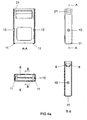
- FIG. 4a illustrates the execution of the tabs 8, 21 by means of sectional views of the metal sleeve. Also, the punctiform impressions 10 and the sheet edges 11 for fixing the insulator are shown. In the region of the insulator and the inwardly bent tabs 8 are opening windows 12 for improved heat dissipation. Opening windows and tabs are defined by cuts 13 in the metal sleeve.
- FIG. 5 shows a lamp glass vessel 14 installed in the metal sleeve state.
- the lamp glass vessel 14 has a glass squeeze base 15, on which the tabs of the metal sleeve as described above attack by pressing.
- the contact pins 16 of the lamp glass vessel 14 engage in the metal tube and are crimped at the points 17 with these. Since the tubes can not be withdrawn from the glass vessel side because of crimping of the cables, crimping 17 increases the strength of the connection between the glass vessel 14 and the metal shell and secures that (in addition) against inadvertent tearing out.
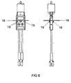
- FIG. 6 shows the basic arrangement of a Positionsjustageflansches 18 on the metal sleeve.
- the Positionjustageflansch has projections 19 which are spot welded to the metal sleeve.
Landscapes
- Fastening Of Light Sources Or Lamp Holders (AREA)
- Non-Portable Lighting Devices Or Systems Thereof (AREA)
- Vessels And Coating Films For Discharge Lamps (AREA)
- Common Detailed Techniques For Electron Tubes Or Discharge Tubes (AREA)
- Connecting Device With Holders (AREA)
Description
- Die Erfindung bezieht sich auf eine Lampe mit angeschlossenem Kabel, insbesondere zum Einbau in ein Reflektorengehäuse für die Beleuchtung und Markierung von Flugzeugrollbahnen.
- Zur Beleuchtung und Markierung von Flugzeugrollbahnen werden Lichtquellen benötigt, die eine geringe Einbauhöhe besitzen und ein i. d. R. möglichst paralleles Strahlenbündel in eine vorgegebene Richtung emittieren. Aufgrund des vergleichsweise kleinen Glasgefäßes, einer langen Lebensdauer und einer hohen Lichtausbeute kommen hierbei bevorzugt Halogenglühlampen zum Einsatz, deren Licht mittels eines Reflektors gebündelt und gerichtet abgestrahlt wird. Denkbar ist aber auch der Einsatz von Hochdruckentladungslampen. Im Folgenden wird der Einfachheit halber von Halogenglühlampen mit Glühwendel ausgegangen, wobei aber auch Hochdruckentladungslampen mit Lichtbogen inbegriffen sein sollen.
- Für die Lichtbündelung ist eine genaue Positionierung der Lichtquelle, also der Glühwendel oder des Lichtbogens, innerhalb der Reflektorumgebung notwendig. Produktionstoleranzen in der Herstellung des Lampenglasgefäßes würden für die genaue Positionierung im Fokus der Reflektorumgebung ein aufwendiges Nachjustieren nach dem Einbau der Lampe erfordern. Um dieser Problematik zu entgehen, wird die Sockelung jedes einzelnen Lampenglasgefäßes der schließlichen Fokusposition im Reflektor schon während des Zusammenbaus der Lampe angepasst. Im Falle einer defekten Lampe wird die gesamte Baugruppe bestehend aus Glasgefäß und Sockelung ausgetauscht und ein Nachjustieren entfällt. Für diesen sog. "Airfield"-Bereich werden also spezielle Halogenglühlampen (und im Sinn dieser Erfindung auch Hochdruckentladungslampen) eingesetzt, bei denen im Übrigen elektrische Anschlusskabel an aus dem eigentlichen Lampenglasgefäß herausgeführte Kontaktstifte angeschlossen sind. Die Erfindung richtet sich daneben aber auch auf Lampen vergleichbarer Bauart für andere Anwendungsgebiete, sei es für den auch außerhalb des Airfield-Bereiches bevorzugt in Betracht kommenden Einbau in Reflektorengehäuse, sei es auch davon unabhängig.
- Die Schrift
DE 198 42 794 A1 offenbart eine Reflektorlampe, die ein Lampengefäß mit aus dessen Ende herausragenden äußeren Stromzuführungen aufweist. Das Lampengefäß ist im Reflektorhals gehaltert, der mit einer Zentrierscheibe versehen ist. Die Stromzuführungen des Lampengefäßes sind innerhalb des Reflektorhalses mit aus dem Reflektorhals herausragenden Kontaktstiften vercrimpt. - Die Aufgabe der vorliegenden Erfindung ist es, eine verbesserte Lampe des beschriebenen Typs und ein entsprechendes Herstellungsverfahren anzugeben. Das Problem wird gelöst durch eine Lampe, die ein Lampenglasgefäß mit aus dessen Ende herausragenden Kontaktstiften aufweist und in einer Sockelaufnahme mit einem Isolator gehaltert ist, wobei die Sockelaufnahme einen Positionsjustageflansch (18) beinhaltet und wobei der Isolator (2, 6) in zumindest einer durchgehenden Bohrung ein metallenes Röhrchen (1) zwischen einem Kontaktstift (16) des Lampengefäßes (14) und einem stromzuleitenden Anschlusskabel (4) haltert, mit welchem Röhrchen (1) der Kontaktstift (16) vercrimpt ist und das Anschlusskabel (4) verbunden ist,
dadurch gekennzeichnet, dass
der Isolator von einer lampenseitig offenen Metallhülse umgeben ist,
sowie durch ein entsprechendes Herstellungsverfahren nach Anspruch 13. - Bevorzugte Ausgestaltungen sind in den abhängigen Ansprüchen angegeben.
- Die Erfinder haben erkannt, dass sich durch Vercrimpen in der Sockelung Lampen mit angeschlossenem Kabel besonders leicht und zuverlässig herstellen lassen. Crimpverbindungen lassen sich im Vergleich zu Schweiß- oder Lötverbindungen ohne Erhitzung und Kontrolle schmelzender Metalle und damit einfacher und kostengünstiger realisieren. Die der Erfindung zugrunde liegende Idee beinhaltet ferner, mittels zumindest eines Metallröhrchens einen Crimpverbindungsanschluss von Kontaktstiften an Anschlusskabeln zu ermöglichen. Das zumindest eine Metallröhrchen ist glasgefäßseitig mit dem entsprechenden Kontaktstift vercrimpt und auf der gegenüberliegenden Seite mit einem stromzuleitenden Kabel verbunden. Das Kabel kann mit dem Röhrchen beispielsweise verschweißt, verlötet oder besonders vorteilhaft ebenfalls vercrimpt sein.
- Vorteilhaft ist auch die Ausformung des zum Vercrimpen notwendigen zusätzlichen Bauelementes als Röhrchen, da durch einfaches Zusammenstecken mit dem Kontaktstift schon Glasgefäß und Kabel in endgültiger Position vorläufig gehaltert werden können und nur noch vercrimpt werden müssen, um eine dauerhafte Verbindung herzustellen. Auch eignet sich die Form eines Röhrchens gut zum Vercrimpen.
- Der Begriff "Röhrchen" ist aus diesem Zusammenhang heraus zu verstehen: Es muss sich nicht zwingend um ein in Umfangsrichtung vollständig geschlossenes Röhrchen handeln. Ein verbleibender Schlitz würde so lange nicht schaden, wie der Kontaktstift eingesteckt und gehalten werden kann. Auch kann es genügen, ein zum Einstecken und Halten des Kontaktstiftes geeignetes Querschnittsprofil des Röhrchens entlang seiner axialen Länge nur stellenweise vorzusehen. Besonders bevorzugt ist dabei ein einfaches Röhrchen mit über die axiale Länge gleichbleibendem Kreisringquerschnitt.
- Zur Stromversorgung der Glühwendel im Inneren des Lampenglasgefäßes befinden sich zwei Stromdurchführungen im Ende des Glasgefäßes, welches Ende einerseits das Lampenglasgefäß abdichtet und andererseits die Glühwendel (oder eine Elektrode) und die Stromzuführungen haltert. Üblicherweise ist das Ende des Lampenglasgefäßes als flaches Ende, insbesondere Glasquetschung, ausgebildet. Die außerhalb der Quetschung stiftförmigen Stromzuführungen weisen im Inneren der Quetschung dann häufig Molybdänfolien auf.
- Die Sockelaufnahme mit dem Lampenglasgefäß kann vorzugsweise wie bekannt mittels eines Positionsjustageflansches in einem Reflektor befestigt werden. Der Flansch ist dabei vorzugsweise an einer Metallhülse montiert, wobei die Position des Flansches auf die ideale Lage der lichterzeugenden Glühwendel innerhalb des Reflektors bezogen ist.
- Zumindest einer der Kontaktstifte muss elektrisch isoliert sein, insbesondere gegenüber einer Sockelaufnahme mit Metallteilen, etwa wie oben erwähnt. Der andere Kontaktstift könnte auch mit der Metallhülse oder anderen leitenden Umgebungsteilen verbunden sein. Der Isolator kann im Minimalfall beispielsweise aus einem Glas- oder Keramikröhrchen bestehen. Bevorzugterweise ist der Isolator ein Keramikquader mit einer den Kontaktstift und das Metallröhrchen aufnehmenden durchgehenden Bohrung. Noch bevorzugter existieren in dem Keramikquader zwei Bohrungen für beide Kontaktstifte, sodass beide Kontaktstifte voneinander und von der Umgebung isoliert sind.
- Bei dem elektrischen Anschluss des oder der Anschlusskabel an dem oder den Metallröhrchen kann für eine Aufweitung von Röhrchen und/oder Kabel gesorgt werden, sodass das Röhrchen nicht mehr zum Lampenglasgefäß hin aus dem Isolator herausgezogen werden kann. Damit kann eine Sicherung gegen ein unbeabsichtigtes Herausreißen des Lampenglasgefäßes aus der Sockelaufnahme erzielt werden. Hier bietet sich vorzugsweise ein Vercrimpen auch der Anschlusskabel in dem Metallröhrchen an.
- Im Falle eines Glasflachendes liegt die Metallhülse vorzugsweise mittels nach innen gebogenen Metalllaschen an dem Flachende an. Dabei können die Metalllaschen auch in Kerben oder hinter Rillen in bzw. auf dem Flachende hinterschnappen und das Lampenglasgefäß zusätzlich in der Sockelaufnahme fixieren. Daraus ergibt sich dann eine besonders effektive Sicherung gegen eine unbeabsichtigte Trennung. Jedenfalls dienen die an der Quetschung angreifenden Laschen einer verbesserten Ableitung der in der Lampe entstehenden Wärme.
- Aufgrund der zumeist schlechten Wärmeleitfähigkeit der als Isolator verwendeten Materialien ist es vorteilhaft, wenn die Metallhülse im Bereich des Isolators Öffnungsfenster zur verbesserten Wärmeabstrahlung aufweist. Vorteilhaft sind diese Öffnungsfenster an den breiteren Seiten der flachen Glasquetschung angebracht.
- Die ins Innere der Metallhülse ragenden und oben erwähnten Laschen lassen sich besonders einfach durch Einschnitte im Blech der Metallhülse realisieren.
- Zusätzliche Öffnungsfenster im Bereich der Laschen ergeben sich in zwangloser Weise, wenn die die Laschen definierenden Einschnitte größer sind als die Laschen selbst und ein zusammenhängendes Gebiet umfassen. Die Einschnitte können beispielsweise mit Stanz- oder Schneidwerkzeugen hergestellt werden.
- Der die metallenen Röhrchen aufnehmende Isolator kann zweiteilig aufgebaut sein. Zum Beispiel kann ein erster Teil die Röhrchen aufnehmen und ein zweiter Teil Bohrungen enthalten, durch welche die Anschlusskabel den Röhrchen zugeführt werden. Dies erleichtert die Montage bzw. die Verbindung von Anschlusskabel und Röhrchen und ermöglicht es, die stromzuleitenden Kabel auf einer längeren Strecke abzuisolieren, beispielsweise um wärmebedingte Schäden an der isolierenden Ummantelung der Kabel zu vermeiden.
- Das Vercrimpen von Kontaktstift und Metallröhrchen kann auch dann noch durchgeführt werden, wenn die Röhrchen bereits in der Sockelaufnahme montiert sind. Dazu befinden sich im Bereich der glasgefäßseitigen Röhrchenenden seitliche Ausnehmungen in dem Isolator, welche in Verbindung mit den Öffnungsfenstern der Metallhülse einen Zugang zum Vercrimpen nach Einstecken der Kontaktstifte ermöglichen.
- Weist der Isolator diese Öffnungsfenster nicht auf, kann der Schritt des Vercrimpens von Röhrchen und Kontaktstift auch vor dem Zusammenbau stattfinden.
- Im Falle eines zweiteiligen Isolators mit seitlichen Zugängen zum Vercrimpen in dem glasgefäßseitigen Teil kann vorteilhaft folgende Reihenfolge beim Zusammenbau der Lampe eingehalten werden: Zuerst werden die (oder das Metallröhrchen in die durchgehende Bohrung des glasgefäßseitigen ersten Isolatorteils gesteckt, dann werden (das oder) die Anschlusskabel mit (dem oder) den Röhrchen vercrimpt, wobei die kabelseitigen Röhrchenenden so verformt werden, dass ein glasgefäßseitiges Herausziehen der Röhrchen verhindert wird. Daraufhin wird der zweite Isolatorteil über das oder die Anschlusskabel gezogen, sodass die freistehenden kabelseitigen Röhrchenenden vom Isolator eingeschlossen werden. Die Gesamtheit von Röhrchen, Isolator und Kabeln wird nun in die Metallhülse eingelassen, und in dieser durch punktförmiges Eindrücken der Metallhülsenwand einerseits und durch Umklappen eines entsprechenden Vorsprungs am Hülsenblech andererseits in der Metallhülse fixiert. Die Fixierung des Isolators in der Metallhülse kann im Prinzip auch anders bewerkstelligt werden, z. B. durch Verschrauben.
- Im Folgenden soll die Erfindung anhand von Ausführungsbeispielen näher erläutert werden.
- Figur 1
- zeigt einen ersten Isolatorteil mit zwei darin gehalterten metallenen Röhrchen.
- Figur 2
- zeigt das Ensemble aus
Figur 1 mit mit den Röhrchen verbundenen Anschlusskabeln. - Figur 3
- zeigt die Baugruppe aus
Figur 2 mit einem zwei- ten Isolatorteil. - Figur 4
- zeigt aufbauend auf
Figur 3 die Umhüllung des Isolators durch die Metallhülse. - Figur 4a
- zeigt Querschnitte der Metallhülse aus
Figur 4 . - Figur 5
- zeigt die Baugruppe aus
Figur 4 , wobei die Me- tallhülse auch ein Lampenglasgefäß hält. - Figur 6
- zeigt die Baugruppe aus
Figur 5 , der ein Posi- tionierflansch hinzugefügt wurde. - Mithin illustrieren die
Figuren 1 - 6 in dieser Reihenfolge den Ablauf eines bevorzugten Herstellungsverfahrens und zeigen eine erfindungsgemäße Lampe inFigur 6 . -
Figur 1 zeigt zwei Metallröhrchen 1, die in einem ersten Isolatorteil 2 aus Keramik gehaltert sind. Dieses erste Isolatorteil 2 weist an den Röhrchenenden, die im eingebauten Zustand dem Lampenglasgefäß zugewandt sind, Materialaussparungen 3 auf, welche in einem späteren Verfahrensschritt einen Zugang zum Vercrimpen der Röhrchen 1 ermöglichen. Die Röhrchen 1 weisen an ihrem glasgefäßseitigen Ende eine Aufweitung 20 auf, die die Röhrchen gegen ein kabelseitiges Herausziehen oder Herausfallen aus dem ersten Isolatorteil sichert. Die Ausdehnung des ersten Isolatorteils in Richtung der Röhrchenachse ist dabei so bemessen, dass ein zum Vercrimpen mit den Kabeln ausreichender Teil der Röhrchen aus dem Isolatorteil herausragt, wenn die Aufweitung 20 der Röhrchen plan mit der entsprechenden Oberfläche des ersten Isolatorteils abschließt. -
Figur 2 zeigt den Anschluss von zwei Anschlusskabeln 4 an die Röhrchen 1. An ihrem röhrchenseitigen Ende sind die Kabel 4 abisoliert und mit den Röhrchen vercrimpt. Die Vercrimpung 5 verquetscht die Röhrchen dergestalt, dass ein lampenglasgefäßseitiges Herausziehen der Röhrchen aus dem ersten Isolatorteil nicht mehr möglich ist (nicht dargestellt). Vorteilhafterweise sind die Röhrchen bereits vom ersten Isolatorteil gehaltert, was das Vercrimpen mit den Kabelenden vereinfacht. -
Figur 3 zeigt einen zweiten Isolatorteil 6, der sich direkt an den ersten Isolatorteil 2 anschließt und die Vercrimpung von Röhrchen 1 und Anschlusskabeln 4 vollständig umgibt. Ebenfalls dargestellt sind Kabelschuhe 7, die beispielhaft für eine Verbindung der Kabelenden mit einer Stromversorgung stehen. - In
Figur 4 umgibt eine erfindungsgemäße Metallhülse 9 die Baugruppe aus erstem Isolatorteil , zweitem Isolatorteil und Metallröhrchen. Diese Baugruppe wird in der Metallhülse fixiert durch einen punktförmigen Eindruck 10 der Metallhülse und nach innen umgebogene Blechkanten 11. Die Metallhülse weist auf den breiten Seiten Metalllaschen 8 auf, welche später zur Wärmeableitung an der Glasquetschung angreifen und diese gegebenenfalls auch durch Hinterschnappen in entsprechenden Vertiefungen und Rillen in der Metallhülse 9 fixieren können. Dem gleichen Prinzip folgt die Metalllasche 21 auf einer schmalen Seite der Metallhülse. Die an das Lampenglasgefäß angedrückten Metalllaschen 8, 21 dienen ebenfalls einer verbesserten Wärmeabfuhr. Dies ist insbesondere deswegen nützlich, da die im Betrieb der Lampe auftretenden hohen Temperaturen des Lampenglasgefäßes nachteilige Auswirkungen auf die Dichtigkeit der Glasdichtung im Bereich der stromzuführenden Kontaktstifte haben und die prinzipiell erreichbare Lebensdauer der Lampe verkürzen. Dieses Problem wird als Ursache für den Verlust der Dichtigkeit durch Oxidation der als Stromdurchführung verwendeten Molybdänfolien betrachtet. Aufgrund der kompakten Reflektorbauweise, der insbesondere bei in die Flugzeugrollbahn eingelassenen Reflektoren und infolge dessen eingeschränkter Wärmeabfuhr durch Konvektion ist ein verbesserter Abtransport der auf den Bereich der Quetschung übertragenen Wärme von großer Bedeutung bei der Vermeidung von Frühausfällen. -
Figur 4a verdeutlicht die Ausführung der Laschen 8, 21 mittels Schnittdarstellungen der Metallhülse. Auch die punktförmigen Eindrücke 10 und die Blechkanten 11 zum Fixieren des Isolators sind dargestellt. Im Bereich des Isolators und der nach innen gebogenen Laschen 8 befinden sich Öffnungsfenster 12 zur verbesserten Wärmeabstrahlung. Öffnungsfenster und Laschen sind durch Einschnitte 13 in der Metallhülse definiert. -
Figur 5 zeigt ein Lampenglasgefäß 14 in in die Metallhülse eingebautem Zustand. Das Lampenglasgefäß 14 besitzt einen Glasquetschsockel 15, an welchem die Laschen der Metallhülse wie oben beschrieben durch Andrücken angreifen. Die Kontaktstifte 16 des Lampenglasgefäßes 14 greifen in die Metallröhrchen ein und sind an den Punkten 17 mit diesen vercrimpt. Da die Röhrchen aufgrund der mit der Vercrimpung der Kabel einhergehenden Quetschung der kabelseitigen Enden nicht glasgefäßseitig herausgezogen werden können, erhöht die Vercrimpung 17 die Festigkeit der Verbindung von Glasgefäß 14 und Metallhülse und sichert jenes (zusätzlich) gegen ein unbeabsichtigtes Herausreißen. -
Figur 6 zeigt die prinzipielle Anordnung eines Positionsjustageflansches 18 an der Metallhülse. Der Positionsjustageflansch weist Vorsprünge 19 auf, welche mit der Metallhülse punktverschweißt sind.
Claims (21)
- Lampe, die ein Lampenglasgefäß(14) mit aus dessen Ende (15) herausragenden Kontaktstiften (16) aufweist und in einer Sockelaufnahme (9) mit einem Isolator (2, 6) gehaltert ist, wobei die Sockelaufnahme einen Positionsjustageflansch (18) beinhaltet und wobei der Isolator (2, 6) in zumindest einer durchgehenden Bohrung ein metallenes Röhrchen (1) zwischen einem Kontaktstift (16) des Lampengefäßes (14) und einem stromzuleitenden Anschlusskabel (4) haltert, mit welchem Röhrchen (1) der Kontaktstift (16) vercrimpt ist und das Anschlusskabel (4) verbunden ist,
dadurch gekennzeichnet, dass der Isolator von einer lampenseitig offenen Metallhülse (9) umgeben ist. - Lampe nach Anspruch 1, die eine Halogenglühlampe ist.
- Lampe nach Anspruch 1 oder 2, deren Ende (15) ein flaches Glasende (15) ist und deren Metallhülse (9) nach innen gebogene Laschen (8, 21) zur Anlage an dem Flachende (15) aufweist.
- Lampe nach Anspruch 3, wobei die nach innen gebogenen Laschen (8, 21) durch Einschnitte (13) in der Metallhülse (9) definiert sind.
- Lampe nach einem der vorstehenden Ansprüche, deren Metallhülse (9) zumindest im Bereich des Isolators (2, 6) seitliche Öffnungsfenster (13) aufweist.
- Lampe nach Anspruch 4 und 5, wobei die Einschnitte größer (13) als die Laschen (8) sind und Öffnungsfenster (13) bilden.
- Lampe nach einem der vorstehenden Ansprüche, deren Isolator (2, 6) mehrteilig aufgebaut ist, wobei jedes Teil (2, 6) zumindest eine durchgehende Bohrung zur Aufnahme des Röhrchens (1) aufweist.
- Lampe nach Anspruch 5, auch in Verbindung mit Anspruch 6 oder 7, deren Isolator (2, 6) seitliche Zugänge (20) zu den lampenseitigen Röhrchenenden zum Vercrimpen aufweist.
- Lampe nach einem der vorstehenden Ansprüche, bei der das Anschlusskabel (4) an dem Röhrchen (1) so angeschlossen ist, dass das Röhrchen (1) gegen ein lampenglasgefäßseitiges Herausziehen aus der Bohrung des Isolators (2, 6) gesichert ist.
- Lampe nach einem der vorstehenden Ansprüche, bei der das Anschlusskabel (4) mit dem Röhrchen (1) vercrimpt ist.
- Verwendung einer Lampe nach einem der Ansprüche 1 - 10 zur Flugzeugrollbahnbeleuchtung.
- Verfahren zur Herstellung einer Lampe, bei dem ein Lampenglasgefäß (14) mit aus dessen Ende (15) herausragenden Kontaktstiften (16) in einer Sockelaufnahme mit einem Isolator (2, 6) gehaltert wird, wobei die Sockelaufnahme einen Positionsjustageflansch (18) beinhaltet und wobei zumindest ein Kontaktstift (16) mit einem metallenen Röhrchen (1) vercrimpt wird, welches Röhrchen (1) mit einem stromzuleitenden Anschlusskabel (4) verbunden und in einer durchgehenden Bohrung im Isolator (2, 6) gehaltert wird, dadurch gekennzeichnet, dass der Isolator (2, 6) von einer lampenseitig offenen Metallhülse (9) umgeben ist.
- Verfahren nach Anspruch 12, wobei der Schritt des Vercrimpens mindestens eines Kontaktstiftes (16) mit dem Röhrchen (1) zeitlich nach dem Zusammenbau des Isolators (2, 6), des Lampenglasgefäßes (14), der Metallhülse (9) und des Röhrchens (1) stattfindet.
- Verfahren nach Anspruch 12 oder 13, wobei das Zusammensetzen von Isolator (2, 6) und Röhrchen (1) vor deren Einbau in die Metallhülse (9) stattfindet.
- Verfahren nach Anspruch 12, 13 oder 14, wobei das Verbinden von Röhrchen (1) und Anschlusskabel (4) vor deren Einbau in die Metallhülse (9) stattfindet.
- Verfahren nach einem der Ansprüche 12 - 15, wobei Röhrchen (1) und Anschlusskabel (4) nach dem Zusammensetzen von Röhrchen (1) und Isolator (2, 6) miteinander verbunden werden.
- Verfahren nach einem der Ansprüche 12 - 16, wobei das Anbringen des Positionsjustageflansches (18) direkt dem Schritt des Vercrimpens mindestens eines Kontaktstiftes (16) mit dem Röhrchen (1) folgt.
- Verfahren nach den Ansprüchen 12 - 17 mit folgenden Schritten in folgender Reihenfolge: Einbringen des Röhrchens (1) in einen ersten Isolatorteil (2), Verbinden des Anschlusskabels (4) mit dem Röhrchen (1), Aufziehen eines zweiten Isolatorteils (6), Einbau des Isolators (2, 6) in die Metallhülse (9), Einstecken des Lampenglasgefäßes (14) in die Metallhülse (9), Vercrimpen von Kontaktstift (16) und Röhrchen (1), Anbringen des Positionsjustageflansches (18).
- Verfahren nach einem der Ansprüche 12 - 18, wobei Anschlusskabel (4) und Röhrchen (1) durch Vercrimpen so miteinander verbunden werden, dass das Röhrchen (1) gegen ein lampenseitiges Herausziehen aus dem Isolator (2, 6) durch die beim Vercrimpen entstehende Quetschung des kabelseitigen Röhrchenendes gesichert wird.
- Verfahren nach einem der Ansprüche 12 - 19 zur Herstellung einer Lampe nach einem der Ansprüche 1 - 10.
- Verfahren nach Anspruch 19 beinhaltend die Verwendung nach Anspruch 11.
Applications Claiming Priority (1)
| Application Number | Priority Date | Filing Date | Title |
|---|---|---|---|
| PCT/EP2007/061128 WO2009052851A1 (de) | 2007-10-18 | 2007-10-18 | Einbaulampe mit kabel, insbesondere zur flugplatzbefeuerung |
Publications (2)
| Publication Number | Publication Date |
|---|---|
| EP2201590A1 EP2201590A1 (de) | 2010-06-30 |
| EP2201590B1 true EP2201590B1 (de) | 2011-08-17 |
Family
ID=39577806
Family Applications (1)
| Application Number | Title | Priority Date | Filing Date |
|---|---|---|---|
| EP07821493A Not-in-force EP2201590B1 (de) | 2007-10-18 | 2007-10-18 | Einbaulampe mit kabel, insbesondere zur flugplatzbefeuerung |
Country Status (6)
| Country | Link |
|---|---|
| US (1) | US8604682B2 (de) |
| EP (1) | EP2201590B1 (de) |
| JP (1) | JP5140733B2 (de) |
| CN (1) | CN101828245B (de) |
| AT (1) | ATE521080T1 (de) |
| WO (1) | WO2009052851A1 (de) |
Families Citing this family (3)
| Publication number | Priority date | Publication date | Assignee | Title |
|---|---|---|---|---|
| CN103185260A (zh) * | 2011-12-30 | 2013-07-03 | 海洋王照明科技股份有限公司 | 配光系统及嵌入式进近灯 |
| WO2020057657A1 (zh) * | 2018-09-20 | 2020-03-26 | 欧普照明股份有限公司 | 灯具的安装座、照明组件及灯具 |
| WO2020151994A1 (en) * | 2019-01-24 | 2020-07-30 | Signify Holding B.V. | Led filament arrangement |
Family Cites Families (17)
| Publication number | Priority date | Publication date | Assignee | Title |
|---|---|---|---|---|
| US2680236A (en) * | 1950-08-22 | 1954-06-01 | Gen Electric | Crimped contact pin assembly |
| US3848120A (en) * | 1973-10-18 | 1974-11-12 | Thorn Electrical Ind Ltd | Light bulb and reflector assembly |
| US3946263A (en) * | 1974-12-23 | 1976-03-23 | Protzeller Harry W | Encapsulated lamp assembly |
| US4151364A (en) * | 1976-09-29 | 1979-04-24 | Ellis J Scott | Electrical connectors and methods of connecting electrical conductors |
| US4145630A (en) * | 1977-12-05 | 1979-03-20 | Westinghouse Electric Corp. | Halogen-cycle type incandescent lamp |
| US4608624A (en) * | 1985-01-22 | 1986-08-26 | Gte Products Corporation | Projection lamp unit with separable lamp capsule |
| JPS63237369A (ja) * | 1987-03-26 | 1988-10-03 | 日本電気ホームエレクトロニクス株式会社 | ピン端子 |
| JPH01243366A (ja) * | 1988-03-24 | 1989-09-28 | Koito Mfg Co Ltd | 口金付電球 |
| US5165789A (en) * | 1991-07-15 | 1992-11-24 | Womack Robert C | Limited access long stemmed small diameter probe light |
| JP2800493B2 (ja) * | 1991-08-28 | 1998-09-21 | 東芝ライテック株式会社 | 管形白熱電球および機器 |
| JP3103710B2 (ja) * | 1993-12-27 | 2000-10-30 | 松下電子工業株式会社 | 白熱電球および反射鏡付き白熱電球 |
| DE19842794A1 (de) * | 1998-09-18 | 2000-03-23 | Patent Treuhand Ges Fuer Elektrische Gluehlampen Mbh | Reflektorlampe |
| DE29918862U1 (de) * | 1999-10-27 | 2000-03-16 | Shu, Kuo Fen, Hsinchu | Verbesserter Leuchtdiodenglühlampenhalter, der in LED-Typ-Weihnachtslichtlampenbändern verwendet wird |
| US20050136754A1 (en) * | 2003-12-17 | 2005-06-23 | Wilson Carolyn E. | Seamed pin for crimping and welding as used in a fluorescent lamp |
| DE102004006438A1 (de) * | 2004-02-09 | 2005-08-25 | Patent-Treuhand-Gesellschaft für elektrische Glühlampen mbH | Fahrzeugscheinwerferlampe |
| DE102004006439A1 (de) | 2004-02-09 | 2005-08-25 | Patent-Treuhand-Gesellschaft für elektrische Glühlampen mbH | Fahrzeugschweinwerferlampe |
| CN201122574Y (zh) * | 2007-06-28 | 2008-09-24 | 飞利浦(中国)投资有限公司 | 金属卤化物灯 |
-
2007
- 2007-10-18 CN CN2007801011497A patent/CN101828245B/zh not_active Expired - Fee Related
- 2007-10-18 EP EP07821493A patent/EP2201590B1/de not_active Not-in-force
- 2007-10-18 JP JP2010529237A patent/JP5140733B2/ja not_active Expired - Fee Related
- 2007-10-18 WO PCT/EP2007/061128 patent/WO2009052851A1/de not_active Ceased
- 2007-10-18 AT AT07821493T patent/ATE521080T1/de active
- 2007-10-18 US US12/738,816 patent/US8604682B2/en not_active Expired - Fee Related
Also Published As
| Publication number | Publication date |
|---|---|
| JP5140733B2 (ja) | 2013-02-13 |
| ATE521080T1 (de) | 2011-09-15 |
| WO2009052851A1 (de) | 2009-04-30 |
| EP2201590A1 (de) | 2010-06-30 |
| US20100244654A1 (en) | 2010-09-30 |
| CN101828245B (zh) | 2012-07-18 |
| CN101828245A (zh) | 2010-09-08 |
| US8604682B2 (en) | 2013-12-10 |
| JP2011501353A (ja) | 2011-01-06 |
Similar Documents
| Publication | Publication Date | Title |
|---|---|---|
| DE19831042A1 (de) | Beleuchtungssystem mit einer Hochdruckentladungslampe | |
| EP0452743A1 (de) | Kompakte Niederdruckentladungslampe | |
| DE69606602T2 (de) | Gesockelte elektrische lampe | |
| EP1714305B1 (de) | Fahrzeugscheinwerferlampe | |
| EP2201590A1 (de) | Einbaulampe mit kabel, insbesondere zur flugplatzbefeuerung | |
| WO2010124904A1 (de) | Entladungslampe | |
| DE29910604U1 (de) | Reflektorlampe | |
| DE10331510B4 (de) | Kurzbogen-Entladungslampe sowie Lichtquellenvorrichtung | |
| EP0566975B1 (de) | Einseitig gesockelte Hochdruckentladungslampe | |
| DE10048986A1 (de) | Dielektrische Barrieren-Entladungslampe | |
| EP0168031B1 (de) | Elektrische Lampe | |
| DE10133326A1 (de) | Dielektrische Barrieren-Entladungslampe mit Zündhilfe | |
| EP1714306B1 (de) | Fahrzeugscheinwerferlampe | |
| DE10312720A1 (de) | Dielektrische Barriere-Entladungslampe mit Quetschdichtung | |
| EP2020677A2 (de) | Elektrische Lampe mit einem Aussenkolben und einer Einbaulampe sowie ein Verfahren zu deren Herstellung | |
| EP1659617A1 (de) | Leuchtmittel | |
| WO2010025770A1 (de) | Entladungslampe | |
| EP2458614B1 (de) | Elektrische Lampe mit einem Außenkolben und einer Einbaulampe | |
| WO2010127705A1 (de) | Elektrische lampe mit einem aussenkolben und einer einbaulampe | |
| DE102008059635A1 (de) | Integrierte Gasentladungslampe und Verfahren zum Betreiben einer integrierten Gasentladungslampe | |
| DE102008059484A1 (de) | Integrierte Gasentladungslampe mit in den Sockel integrieter Zündelektronik | |
| WO2011018118A1 (de) | Hochdruckentladungslampe mit zündhilfe | |
| DE10029107A1 (de) | Entladungslampe | |
| DE102018201068B4 (de) | Glühlampe für fahrzeugscheinwerfer und herstellungsverfahren | |
| DE102010023000B3 (de) | Strahler mit Quarzglaskolben und Stromdurchführung |
Legal Events
| Date | Code | Title | Description |
|---|---|---|---|
| PUAI | Public reference made under article 153(3) epc to a published international application that has entered the european phase |
Free format text: ORIGINAL CODE: 0009012 |
|
| 17P | Request for examination filed |
Effective date: 20100226 |
|
| AK | Designated contracting states |
Kind code of ref document: A1 Designated state(s): AT BE BG CH CY CZ DE DK EE ES FI FR GB GR HU IE IS IT LI LT LU LV MC MT NL PL PT RO SE SI SK TR |
|
| AX | Request for extension of the european patent |
Extension state: AL BA HR MK RS |
|
| DAX | Request for extension of the european patent (deleted) | ||
| GRAP | Despatch of communication of intention to grant a patent |
Free format text: ORIGINAL CODE: EPIDOSNIGR1 |
|
| GRAS | Grant fee paid |
Free format text: ORIGINAL CODE: EPIDOSNIGR3 |
|
| GRAA | (expected) grant |
Free format text: ORIGINAL CODE: 0009210 |
|
| AK | Designated contracting states |
Kind code of ref document: B1 Designated state(s): AT BE BG CH CY CZ DE DK EE ES FI FR GB GR HU IE IS IT LI LT LU LV MC MT NL PL PT RO SE SI SK TR |
|
| REG | Reference to a national code |
Ref country code: GB Ref legal event code: FG4D Free format text: NOT ENGLISH |
|
| RAP2 | Party data changed (patent owner data changed or rights of a patent transferred) |
Owner name: OSRAM AG |
|
| REG | Reference to a national code |
Ref country code: CH Ref legal event code: EP |
|
| REG | Reference to a national code |
Ref country code: IE Ref legal event code: FG4D Free format text: LANGUAGE OF EP DOCUMENT: GERMAN |
|
| REG | Reference to a national code |
Ref country code: DE Ref legal event code: R096 Ref document number: 502007007996 Country of ref document: DE Effective date: 20111020 |
|
| REG | Reference to a national code |
Ref country code: NL Ref legal event code: VDEP Effective date: 20110817 |
|
| LTIE | Lt: invalidation of european patent or patent extension |
Effective date: 20110817 |
|
| PG25 | Lapsed in a contracting state [announced via postgrant information from national office to epo] |
Ref country code: LT Free format text: LAPSE BECAUSE OF FAILURE TO SUBMIT A TRANSLATION OF THE DESCRIPTION OR TO PAY THE FEE WITHIN THE PRESCRIBED TIME-LIMIT Effective date: 20110817 Ref country code: NL Free format text: LAPSE BECAUSE OF FAILURE TO SUBMIT A TRANSLATION OF THE DESCRIPTION OR TO PAY THE FEE WITHIN THE PRESCRIBED TIME-LIMIT Effective date: 20110817 Ref country code: SE Free format text: LAPSE BECAUSE OF FAILURE TO SUBMIT A TRANSLATION OF THE DESCRIPTION OR TO PAY THE FEE WITHIN THE PRESCRIBED TIME-LIMIT Effective date: 20110817 Ref country code: IS Free format text: LAPSE BECAUSE OF FAILURE TO SUBMIT A TRANSLATION OF THE DESCRIPTION OR TO PAY THE FEE WITHIN THE PRESCRIBED TIME-LIMIT Effective date: 20111217 Ref country code: FI Free format text: LAPSE BECAUSE OF FAILURE TO SUBMIT A TRANSLATION OF THE DESCRIPTION OR TO PAY THE FEE WITHIN THE PRESCRIBED TIME-LIMIT Effective date: 20110817 Ref country code: PT Free format text: LAPSE BECAUSE OF FAILURE TO SUBMIT A TRANSLATION OF THE DESCRIPTION OR TO PAY THE FEE WITHIN THE PRESCRIBED TIME-LIMIT Effective date: 20111219 |
|
| PG25 | Lapsed in a contracting state [announced via postgrant information from national office to epo] |
Ref country code: LV Free format text: LAPSE BECAUSE OF FAILURE TO SUBMIT A TRANSLATION OF THE DESCRIPTION OR TO PAY THE FEE WITHIN THE PRESCRIBED TIME-LIMIT Effective date: 20110817 Ref country code: SI Free format text: LAPSE BECAUSE OF FAILURE TO SUBMIT A TRANSLATION OF THE DESCRIPTION OR TO PAY THE FEE WITHIN THE PRESCRIBED TIME-LIMIT Effective date: 20110817 Ref country code: GR Free format text: LAPSE BECAUSE OF FAILURE TO SUBMIT A TRANSLATION OF THE DESCRIPTION OR TO PAY THE FEE WITHIN THE PRESCRIBED TIME-LIMIT Effective date: 20111118 Ref country code: PL Free format text: LAPSE BECAUSE OF FAILURE TO SUBMIT A TRANSLATION OF THE DESCRIPTION OR TO PAY THE FEE WITHIN THE PRESCRIBED TIME-LIMIT Effective date: 20110817 Ref country code: CY Free format text: LAPSE BECAUSE OF FAILURE TO SUBMIT A TRANSLATION OF THE DESCRIPTION OR TO PAY THE FEE WITHIN THE PRESCRIBED TIME-LIMIT Effective date: 20110817 |
|
| REG | Reference to a national code |
Ref country code: IE Ref legal event code: FD4D |
|
| BERE | Be: lapsed |
Owner name: OSRAM G.M.B.H. Effective date: 20111031 |
|
| PG25 | Lapsed in a contracting state [announced via postgrant information from national office to epo] |
Ref country code: CZ Free format text: LAPSE BECAUSE OF FAILURE TO SUBMIT A TRANSLATION OF THE DESCRIPTION OR TO PAY THE FEE WITHIN THE PRESCRIBED TIME-LIMIT Effective date: 20110817 Ref country code: SK Free format text: LAPSE BECAUSE OF FAILURE TO SUBMIT A TRANSLATION OF THE DESCRIPTION OR TO PAY THE FEE WITHIN THE PRESCRIBED TIME-LIMIT Effective date: 20110817 Ref country code: IE Free format text: LAPSE BECAUSE OF FAILURE TO SUBMIT A TRANSLATION OF THE DESCRIPTION OR TO PAY THE FEE WITHIN THE PRESCRIBED TIME-LIMIT Effective date: 20110817 |
|
| PG25 | Lapsed in a contracting state [announced via postgrant information from national office to epo] |
Ref country code: RO Free format text: LAPSE BECAUSE OF FAILURE TO SUBMIT A TRANSLATION OF THE DESCRIPTION OR TO PAY THE FEE WITHIN THE PRESCRIBED TIME-LIMIT Effective date: 20110817 Ref country code: IT Free format text: LAPSE BECAUSE OF FAILURE TO SUBMIT A TRANSLATION OF THE DESCRIPTION OR TO PAY THE FEE WITHIN THE PRESCRIBED TIME-LIMIT Effective date: 20110817 Ref country code: EE Free format text: LAPSE BECAUSE OF FAILURE TO SUBMIT A TRANSLATION OF THE DESCRIPTION OR TO PAY THE FEE WITHIN THE PRESCRIBED TIME-LIMIT Effective date: 20110817 Ref country code: MC Free format text: LAPSE BECAUSE OF NON-PAYMENT OF DUE FEES Effective date: 20111031 |
|
| REG | Reference to a national code |
Ref country code: CH Ref legal event code: PL |
|
| PLBE | No opposition filed within time limit |
Free format text: ORIGINAL CODE: 0009261 |
|
| STAA | Information on the status of an ep patent application or granted ep patent |
Free format text: STATUS: NO OPPOSITION FILED WITHIN TIME LIMIT |
|
| REG | Reference to a national code |
Ref country code: HU Ref legal event code: AG4A Ref document number: E013108 Country of ref document: HU |
|
| PG25 | Lapsed in a contracting state [announced via postgrant information from national office to epo] |
Ref country code: DK Free format text: LAPSE BECAUSE OF FAILURE TO SUBMIT A TRANSLATION OF THE DESCRIPTION OR TO PAY THE FEE WITHIN THE PRESCRIBED TIME-LIMIT Effective date: 20110817 |
|
| REG | Reference to a national code |
Ref country code: FR Ref legal event code: ST Effective date: 20120629 |
|
| 26N | No opposition filed |
Effective date: 20120521 |
|
| PG25 | Lapsed in a contracting state [announced via postgrant information from national office to epo] |
Ref country code: LI Free format text: LAPSE BECAUSE OF NON-PAYMENT OF DUE FEES Effective date: 20111031 Ref country code: CH Free format text: LAPSE BECAUSE OF NON-PAYMENT OF DUE FEES Effective date: 20111031 Ref country code: BE Free format text: LAPSE BECAUSE OF NON-PAYMENT OF DUE FEES Effective date: 20111031 |
|
| PG25 | Lapsed in a contracting state [announced via postgrant information from national office to epo] |
Ref country code: FR Free format text: LAPSE BECAUSE OF NON-PAYMENT OF DUE FEES Effective date: 20111102 |
|
| REG | Reference to a national code |
Ref country code: DE Ref legal event code: R097 Ref document number: 502007007996 Country of ref document: DE Effective date: 20120521 |
|
| PG25 | Lapsed in a contracting state [announced via postgrant information from national office to epo] |
Ref country code: MT Free format text: LAPSE BECAUSE OF FAILURE TO SUBMIT A TRANSLATION OF THE DESCRIPTION OR TO PAY THE FEE WITHIN THE PRESCRIBED TIME-LIMIT Effective date: 20110817 |
|
| REG | Reference to a national code |
Ref country code: DE Ref legal event code: R081 Ref document number: 502007007996 Country of ref document: DE Owner name: OSRAM GMBH, DE Free format text: FORMER OWNER: OSRAM GESELLSCHAFT MIT BESCHRAENKTER HAFTUNG, 81543 MUENCHEN, DE Effective date: 20110901 Ref country code: DE Ref legal event code: R081 Ref document number: 502007007996 Country of ref document: DE Owner name: OSRAM GMBH, DE Free format text: FORMER OWNER: OSRAM AG, 81543 MUENCHEN, DE Effective date: 20130205 |
|
| PG25 | Lapsed in a contracting state [announced via postgrant information from national office to epo] |
Ref country code: ES Free format text: LAPSE BECAUSE OF FAILURE TO SUBMIT A TRANSLATION OF THE DESCRIPTION OR TO PAY THE FEE WITHIN THE PRESCRIBED TIME-LIMIT Effective date: 20111128 |
|
| PG25 | Lapsed in a contracting state [announced via postgrant information from national office to epo] |
Ref country code: LU Free format text: LAPSE BECAUSE OF NON-PAYMENT OF DUE FEES Effective date: 20111018 |
|
| PG25 | Lapsed in a contracting state [announced via postgrant information from national office to epo] |
Ref country code: BG Free format text: LAPSE BECAUSE OF FAILURE TO SUBMIT A TRANSLATION OF THE DESCRIPTION OR TO PAY THE FEE WITHIN THE PRESCRIBED TIME-LIMIT Effective date: 20111117 |
|
| PG25 | Lapsed in a contracting state [announced via postgrant information from national office to epo] |
Ref country code: TR Free format text: LAPSE BECAUSE OF FAILURE TO SUBMIT A TRANSLATION OF THE DESCRIPTION OR TO PAY THE FEE WITHIN THE PRESCRIBED TIME-LIMIT Effective date: 20110817 |
|
| REG | Reference to a national code |
Ref country code: DE Ref legal event code: R081 Ref document number: 502007007996 Country of ref document: DE Owner name: OSRAM GMBH, DE Free format text: FORMER OWNER: OSRAM GMBH, 81543 MUENCHEN, DE Effective date: 20130823 |
|
| REG | Reference to a national code |
Ref country code: AT Ref legal event code: MM01 Ref document number: 521080 Country of ref document: AT Kind code of ref document: T Effective date: 20121031 |
|
| PG25 | Lapsed in a contracting state [announced via postgrant information from national office to epo] |
Ref country code: AT Free format text: LAPSE BECAUSE OF NON-PAYMENT OF DUE FEES Effective date: 20121031 |
|
| PGFP | Annual fee paid to national office [announced via postgrant information from national office to epo] |
Ref country code: HU Payment date: 20171016 Year of fee payment: 11 |
|
| PGFP | Annual fee paid to national office [announced via postgrant information from national office to epo] |
Ref country code: GB Payment date: 20171019 Year of fee payment: 11 |
|
| GBPC | Gb: european patent ceased through non-payment of renewal fee |
Effective date: 20181018 |
|
| PG25 | Lapsed in a contracting state [announced via postgrant information from national office to epo] |
Ref country code: HU Free format text: LAPSE BECAUSE OF NON-PAYMENT OF DUE FEES Effective date: 20181019 |
|
| PG25 | Lapsed in a contracting state [announced via postgrant information from national office to epo] |
Ref country code: GB Free format text: LAPSE BECAUSE OF NON-PAYMENT OF DUE FEES Effective date: 20181018 |
|
| PGFP | Annual fee paid to national office [announced via postgrant information from national office to epo] |
Ref country code: DE Payment date: 20211020 Year of fee payment: 15 |
|
| REG | Reference to a national code |
Ref country code: DE Ref legal event code: R119 Ref document number: 502007007996 Country of ref document: DE |
|
| PG25 | Lapsed in a contracting state [announced via postgrant information from national office to epo] |
Ref country code: DE Free format text: LAPSE BECAUSE OF NON-PAYMENT OF DUE FEES Effective date: 20230503 |
|
| P01 | Opt-out of the competence of the unified patent court (upc) registered |
Effective date: 20230821 |