EP2201653B1 - Dispositif de fabrication de faisceaux et procédé de production de faisceaux de câbles - Google Patents
Dispositif de fabrication de faisceaux et procédé de production de faisceaux de câbles Download PDFInfo
- Publication number
- EP2201653B1 EP2201653B1 EP08802351.0A EP08802351A EP2201653B1 EP 2201653 B1 EP2201653 B1 EP 2201653B1 EP 08802351 A EP08802351 A EP 08802351A EP 2201653 B1 EP2201653 B1 EP 2201653B1
- Authority
- EP
- European Patent Office
- Prior art keywords
- cable
- end portion
- gripping
- transfer
- connector
- Prior art date
- Legal status (The legal status is an assumption and is not a legal conclusion. Google has not performed a legal analysis and makes no representation as to the accuracy of the status listed.)
- Not-in-force
Links
- 238000000034 method Methods 0.000 title claims description 27
- 238000004519 manufacturing process Methods 0.000 title claims description 19
- 230000007246 mechanism Effects 0.000 claims description 36
- 238000002360 preparation method Methods 0.000 claims description 17
- 238000006073 displacement reaction Methods 0.000 claims 1
- 238000005520 cutting process Methods 0.000 description 5
- 238000010276 construction Methods 0.000 description 2
- 238000010586 diagram Methods 0.000 description 1
Images






Classifications
-
- H—ELECTRICITY
- H01—ELECTRIC ELEMENTS
- H01R—ELECTRICALLY-CONDUCTIVE CONNECTIONS; STRUCTURAL ASSOCIATIONS OF A PLURALITY OF MUTUALLY-INSULATED ELECTRICAL CONNECTING ELEMENTS; COUPLING DEVICES; CURRENT COLLECTORS
- H01R43/00—Apparatus or processes specially adapted for manufacturing, assembling, maintaining, or repairing of line connectors or current collectors or for joining electric conductors
- H01R43/28—Apparatus or processes specially adapted for manufacturing, assembling, maintaining, or repairing of line connectors or current collectors or for joining electric conductors for wire processing before connecting to contact members, not provided for in groups H01R43/02 - H01R43/26
-
- Y—GENERAL TAGGING OF NEW TECHNOLOGICAL DEVELOPMENTS; GENERAL TAGGING OF CROSS-SECTIONAL TECHNOLOGIES SPANNING OVER SEVERAL SECTIONS OF THE IPC; TECHNICAL SUBJECTS COVERED BY FORMER USPC CROSS-REFERENCE ART COLLECTIONS [XRACs] AND DIGESTS
- Y10—TECHNICAL SUBJECTS COVERED BY FORMER USPC
- Y10T—TECHNICAL SUBJECTS COVERED BY FORMER US CLASSIFICATION
- Y10T29/00—Metal working
- Y10T29/49—Method of mechanical manufacture
- Y10T29/49002—Electrical device making
- Y10T29/49117—Conductor or circuit manufacturing
- Y10T29/49169—Assembling electrical component directly to terminal or elongated conductor
-
- Y—GENERAL TAGGING OF NEW TECHNOLOGICAL DEVELOPMENTS; GENERAL TAGGING OF CROSS-SECTIONAL TECHNOLOGIES SPANNING OVER SEVERAL SECTIONS OF THE IPC; TECHNICAL SUBJECTS COVERED BY FORMER USPC CROSS-REFERENCE ART COLLECTIONS [XRACs] AND DIGESTS
- Y10—TECHNICAL SUBJECTS COVERED BY FORMER USPC
- Y10T—TECHNICAL SUBJECTS COVERED BY FORMER US CLASSIFICATION
- Y10T29/00—Metal working
- Y10T29/49—Method of mechanical manufacture
- Y10T29/49002—Electrical device making
- Y10T29/49117—Conductor or circuit manufacturing
- Y10T29/49174—Assembling terminal to elongated conductor
-
- Y—GENERAL TAGGING OF NEW TECHNOLOGICAL DEVELOPMENTS; GENERAL TAGGING OF CROSS-SECTIONAL TECHNOLOGIES SPANNING OVER SEVERAL SECTIONS OF THE IPC; TECHNICAL SUBJECTS COVERED BY FORMER USPC CROSS-REFERENCE ART COLLECTIONS [XRACs] AND DIGESTS
- Y10—TECHNICAL SUBJECTS COVERED BY FORMER USPC
- Y10T—TECHNICAL SUBJECTS COVERED BY FORMER US CLASSIFICATION
- Y10T29/00—Metal working
- Y10T29/49—Method of mechanical manufacture
- Y10T29/49826—Assembling or joining
-
- Y—GENERAL TAGGING OF NEW TECHNOLOGICAL DEVELOPMENTS; GENERAL TAGGING OF CROSS-SECTIONAL TECHNOLOGIES SPANNING OVER SEVERAL SECTIONS OF THE IPC; TECHNICAL SUBJECTS COVERED BY FORMER USPC CROSS-REFERENCE ART COLLECTIONS [XRACs] AND DIGESTS
- Y10—TECHNICAL SUBJECTS COVERED BY FORMER USPC
- Y10T—TECHNICAL SUBJECTS COVERED BY FORMER US CLASSIFICATION
- Y10T29/00—Metal working
- Y10T29/51—Plural diverse manufacturing apparatus including means for metal shaping or assembling
-
- Y—GENERAL TAGGING OF NEW TECHNOLOGICAL DEVELOPMENTS; GENERAL TAGGING OF CROSS-SECTIONAL TECHNOLOGIES SPANNING OVER SEVERAL SECTIONS OF THE IPC; TECHNICAL SUBJECTS COVERED BY FORMER USPC CROSS-REFERENCE ART COLLECTIONS [XRACs] AND DIGESTS
- Y10—TECHNICAL SUBJECTS COVERED BY FORMER USPC
- Y10T—TECHNICAL SUBJECTS COVERED BY FORMER US CLASSIFICATION
- Y10T29/00—Metal working
- Y10T29/51—Plural diverse manufacturing apparatus including means for metal shaping or assembling
- Y10T29/5193—Electrical connector or terminal
-
- Y—GENERAL TAGGING OF NEW TECHNOLOGICAL DEVELOPMENTS; GENERAL TAGGING OF CROSS-SECTIONAL TECHNOLOGIES SPANNING OVER SEVERAL SECTIONS OF THE IPC; TECHNICAL SUBJECTS COVERED BY FORMER USPC CROSS-REFERENCE ART COLLECTIONS [XRACs] AND DIGESTS
- Y10—TECHNICAL SUBJECTS COVERED BY FORMER USPC
- Y10T—TECHNICAL SUBJECTS COVERED BY FORMER US CLASSIFICATION
- Y10T29/00—Metal working
- Y10T29/53—Means to assemble or disassemble
- Y10T29/5313—Means to assemble electrical device
- Y10T29/53174—Means to fasten electrical component to wiring board, base, or substrate
-
- Y—GENERAL TAGGING OF NEW TECHNOLOGICAL DEVELOPMENTS; GENERAL TAGGING OF CROSS-SECTIONAL TECHNOLOGIES SPANNING OVER SEVERAL SECTIONS OF THE IPC; TECHNICAL SUBJECTS COVERED BY FORMER USPC CROSS-REFERENCE ART COLLECTIONS [XRACs] AND DIGESTS
- Y10—TECHNICAL SUBJECTS COVERED BY FORMER USPC
- Y10T—TECHNICAL SUBJECTS COVERED BY FORMER US CLASSIFICATION
- Y10T29/00—Metal working
- Y10T29/53—Means to assemble or disassemble
- Y10T29/5313—Means to assemble electrical device
- Y10T29/532—Conductor
- Y10T29/53243—Multiple, independent conductors
-
- Y—GENERAL TAGGING OF NEW TECHNOLOGICAL DEVELOPMENTS; GENERAL TAGGING OF CROSS-SECTIONAL TECHNOLOGIES SPANNING OVER SEVERAL SECTIONS OF THE IPC; TECHNICAL SUBJECTS COVERED BY FORMER USPC CROSS-REFERENCE ART COLLECTIONS [XRACs] AND DIGESTS
- Y10—TECHNICAL SUBJECTS COVERED BY FORMER USPC
- Y10T—TECHNICAL SUBJECTS COVERED BY FORMER US CLASSIFICATION
- Y10T29/00—Metal working
- Y10T29/53—Means to assemble or disassemble
- Y10T29/5313—Means to assemble electrical device
- Y10T29/53261—Means to align and advance work part
-
- Y—GENERAL TAGGING OF NEW TECHNOLOGICAL DEVELOPMENTS; GENERAL TAGGING OF CROSS-SECTIONAL TECHNOLOGIES SPANNING OVER SEVERAL SECTIONS OF THE IPC; TECHNICAL SUBJECTS COVERED BY FORMER USPC CROSS-REFERENCE ART COLLECTIONS [XRACs] AND DIGESTS
- Y10—TECHNICAL SUBJECTS COVERED BY FORMER USPC
- Y10T—TECHNICAL SUBJECTS COVERED BY FORMER US CLASSIFICATION
- Y10T29/00—Metal working
- Y10T29/53—Means to assemble or disassemble
- Y10T29/53991—Work gripper, anvil, or element
Definitions
- the invention relates to a harness making device, a pivoting gripping device, and a cable preparation device for use in a harness making device of this type, as well as a method for the production of cable harnesses.
- Harness making devices for the automatic construction of cable harnesses are known from the state of the art.
- cables are pulled from a supply, usually a cable drum, in a desired length by a robot arm and introduced to connection devices, in which said cables are connected to cable connectors.
- the robot arm requires considerable operating space, it is not possible for a plurality of connection devices to be arranged close together.
- the known harness making devices generally cannot produce cable harnesses with especially short cable lengths.
- US 5 159 749 A discloses a harness making device according to the preamble of claim 1.
- An object of the present invention is therefore to provide a harness making device and a method, for the production of cable harnesses, so that cable harnesses with especially short cable lengths can be produced efficiently.
- harness making device according to the independent claim 1 and a method for the production of cable harnesses according to claim 22.
- the invention further relates to a pivoting gripping device according to claim 16 and a cable preparation device according to claim 21 for use in a harness making device of this type for the production of cable harnesses.
- the pivoting gripping device in a harness making device according to the independent claim 1 is arranged in a fixed position between two receiving positions for each at least one connection mechanism, and the cables are introduced to the pivoting gripping device by a cable transfer. Accordingly, the pivoting gripping device requires little lateral space, in such a way that at least two receiving positions can be arranged opposite one another at a small distance. It is thus possible, with a harness making device according to the invention, to produce cable harnesses with an especially short cable length.
- the distance between the receiving positions is no more than 150 mm, preferably no more than 140 mm.
- the harness making device is constructed for the production of plug connections, in particular for the production of IDC connections, such as those frequently used in cable harnesses.
- connection mechanism is constructed in such a way that the connector(s) used can be moved in a plane which is perpendicular to the end portion of the cable, so that the end portion of the cable can optionally be positioned in front of one of a plurality of receiving positions of the connector. In this way, it is possible to produce various cable harnesses with different wiring patterns in a simple manner.
- the pivoting gripping device comprises at least one gripping arm, which in turn comprises an actuator, the gripping arm being movable via actuation of the actuator by one of the connection mechanisms.
- the gripping arm can thus be moved by the connection mechanism without the pivoting gripping device having to have its own drive for moving the gripping arm.
- the gripping arm is rotatable in a plane which lies parallel to the end portion of the cable. In this way, both ends of the cable can be connected with the same connector when using a connection mechanism. Particularly, the gripping arm is movable independently from the cable transfer and from the cable preparation device.
- the harness making device is constructed in such a way that the introduction and connection of at least one end portion of a first cable can be carried out simultaneously with the transfer of a second cable and simultaneously with the preparation of a third cable. In this way, the harness making device can be operated particularly efficiently and a large number of cable harnesses can be produced per unit time.
- the invention further comprises a pivoting gripping device for use in a harness making device according to the invention, said harness making device comprising a first servo motor, to move the at least one gripping arm parallel to the end portion of the cable, and a swivel drive, to turn the pivoting gripping device.
- the swivel drive is attached vertically above or below the servo motor.
- the invention also comprises a cable preparation device for use in a harness making device according to the invention, which comprises a loop-layer for measuring off the desired cable length.
- the loop-layer comprises a cable hold-down, to hold the cable down when laying down the loop. This ensures that the loop is formed in a defined direction, increasing the reliability and operating safety of the loop-layer.
- Fig. 1 is a schematic representation, in a plan view, of a harness making device 1 according to the invention.
- the upper region of Fig. 1 schematically shows an arrangement of four cable drums 40, from which the cable 32, used for the production of the cable harnesses, is removed by a cable preparation device 10 arranged underneath.
- the cable preparation device 10 comprises a loop-layer 12, which produces a cable portion of the desired length and forms a cable loop.
- the cable 32 prepared in this manner is taken up by the cable transfer 8, which is arranged to the left of the loop-layer 12 and extends horizontally, and transferred to the pivoting gripping device 6.
- a receiving position 7, 9 is arranged, in each case comprising a connection mechanism 2, 3, each with a connector 4, 5.
- the pivoting gripping device 6 positions the two ends of the cable 32, which have been delivered by the cable transfer 8, in front of the desired receiving positions of the connectors 4, 5 in such a way that the ends of the cable are connected to the desired receiving position of the connector 4, 5 by the connection mechanism 2, 3.
- the distance between the two connectors i.e. the cable length of the cable harness produced, is 140 mm in the embodiment shown in Fig. 1 .
- Fig. 2 is a perspective view of a pivoting gripping device 6 for use in a harness making device 1 according to the invention.
- the pivoting gripping device 6 has two gripping arms 14, 16 for picking up one cable end each.
- the gripping arms are movable in the vertical direction.
- the gripping arms 14, 16 comprise actuators 18, 20, which the connection mechanism 2, 3 (not shown in Fig. 2 ) can engage in order to move the gripping arm 14, 16 in the vertical direction.
- the gripping arms 14, 16 are fastened to a holding plate 44 in such a way as to be laterally displaceable.
- On the holding plate 44 are disposed two first servo motors 36, 37, each of which is provided for moving a respective gripping arm 14, 16.
- a frame 46 On the holding plate 44 is arranged a frame 46, which is rotatably connected to a swivel drive 38, which is arranged above the frame 46. Above the swivel drive 38 is arranged a second servo motor 48, to drive the swivel drive 38 and thus to rotate the frame 46 together with the first servo motor 36, the holding plate 44 and the gripping arms 14 and 16.
- Control and supply cables 49 are attached to the second servo motor 48, in order to supply current and control signals to the pivoting gripping device 6.
- the pivoting gripping device 6 has a small width, in such a way that the arrangement can even be used between receiving positions 7, 9 arranged close to one another.
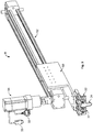
- Fig. 3 shows a cable transfer 8 for use in a harness making device 1 according to the invention.
- the cable transfer 8 comprises four cable transfer grippers 22, which hold a cable 32 with a loop 34.
- the cable transfer grippers 22 are fastened to a cable transfer slide 50 arranged above them.
- the cable transfer slide 50 is held by a cable transfer rail 52, which extends diagonally upwards and on which said slide is displaceable.
- a third servo motor 54 which moves the cable transfer slide 50, for example via a toothed belt (not shown) along the cable transfer rail 52, in order to transfer the cable 32 from the loop-layer 12 (not shown in Fig. 3 ) to the pivoting gripping device 6 (not shown in Fig. 3 ).
- Control and supply cables 55 are attached to the third servo motor 54 to supply current and control signals to the cable transfer 8.
- Fig. 4 shows a loop-layer 12 for use in a harness making device 1 according to the invention.
- the loop-layer 12 comprises a fixed gripper 26, and a movable gripper 28 to the right thereof.
- the two grippers 26, 28 hold a cable 32 with a loop 34.
- the fixed gripper 26 is mounted fixedly on the on the rail 58 of the loop-layer 12.
- the movable gripper 28 is mounted on a slide 56, which is mounted on the rail 58 and movable along the rail.
- a fourth servo motor 60 At the right-hand end of the rail 58, below the rail 58, is arranged a fourth servo motor 60, which drives the slide 56, for example by use of a toothed belt (not shown).
- Control and supply cables 61 are attached to the fourth servo motor 60 to supply current and control signals to the loop-layer 12.
- a fastener 59 is provided below the rail 58 in order to fasten the loop-layer to, for example, a frame.
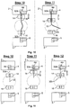
- Fig. 5 to 12 show method steps for the production of cable harnesses.
- Fig. 5 shows, in steps 1 to 4, the measuring off of the desired cable length and the laying down of the loop 34 in the loop-layer 12.
- the movable gripper 28 is guided up against the fixed gripper 26.
- the loop-layer 12 is positioned in such a way as to lie against a cutting knife 62.
- a cable 32 is guided through between the blades of a cutting knife 62, into the open grippers 26, 28 of the loop-layer 12, by the cable preparation device 10.
- the movable gripper 28 is closed and has been distanced from the fixed gripper 26 in accordance with the desired cable length.
- the fixed gripper 26 is opened again.
- the loop-layer 12 has been distanced somewhat from the cutting knife 62, in such a way that a piece of the cable remains between the cutting knife 62 and the fixed gripper 26.
- the cable 32 is fixed by closing the fixed gripper 26.
- the cable 32 is cut to the desired length.
- a cable hold-down 30 is introduced into the region between the fixed gripper 26 and the movable gripper 28, to hold the cable down.
- the movable gripper 28 is moved onto the fixed gripper 26, both of the grippers 26, 28 being closed. In this way, the cable 32 forms a loop 34 in cooperation with the cable hold-down 30.
- two cable transfer grippers 22 are moved to either side of the movable gripper 28 and the fixed gripper 26.
- the distance between the cable transfer grippers 22 is dimensioned in such a way that the movable gripper 28 and the fixed gripper 26 each fit between two cable transfer grippers 22.
- Fig. 6 shows, in steps 6 to 8, the transfer by the cable transfer 8 of a cable prepared by the loop-layer 12.
- the gripping arms of the transfer grippers 22 are closed and the fixed gripper 26 and the movable gripper 28 of the loop-layer 12 are opened.
- the cable 32 is transferred from the loop-layer 12 in the direction of the connection mechanism 2, 3 (not shown) by the cable transfer grippers 22.
- the cable transfer grippers 22 have positioned the cable 32 in the still open gripping arms 14, 16 of the pivoting gripping device 6 between the receiving positions 7, 9.
- the distance between the cable transfer grippers 22 is dimensioned in such a way that a gripping arm 14, 16 of the pivoting gripping device 6 fits between two cable transfer grippers 22 in each case.
- the gripping arms 14, 16 of the pivoting gripping device 6 are closed in order to hold the cable 32, and the cable transfer grippers 22 are opened in order to release the cable 32.
- the cable transfer grippers 22 are moved out of the region of the pivoting gripping device 6.
- Fig. 7 shows the connection of the two ends of the cable 32 to the connectors 4, 5 in the connection mechanism 2, 3 for the production of what is known as a jumper connection.
- the connectors 4, 5 are arranged in the connection mechanism 2, 3 in such a way that the first receiving positions 4a, 5a thereof lie opposite the ends of the cable 32.
- the gripping arms 14, 16 are moved in the direction of the connection mechanism 2, 3 in such a way that the cable ends 32a, 32b are introduced into the connectors 4, 5.
- the cable ends 32a, 32b are connected to the connectors 4, 5 in a step not shown in Fig. 7 .
- the gripping arms 14, 16 of the pivoting gripping device 6 are opened in order to release the cable 32 and moved back into the starting position to receive a further cable 32.
- the connectors 4, 5 are displaced within the connection mechanism 2, 3 perpendicular to the extension of the cable 32 in such a way that in the next step, the ends of the cable 32 are arranged opposite two receiving positions 4b and 5b. In this way, respectively opposite connection positions of the connectors 4, 5 are connected by a cable 32.
- the method shown in Fig. 8 follows on from the ninth step shown in Fig. 6 and represents a method for the production of a bridge connection.
- the second gripping arm 16 remains in the starting position thereof.
- the first gripping arm 14 is released and moved into the starting position thereof, whilst the second gripping arm 16 remains closed.
- the gripping arms 14, 16 together perform a 180° rotation about an axis, A, lying in between them, in such a way as to swap positions.
- the first connector 4 is displaced in a plane perpendicular to the cable 32 by the first connection mechanism 2 in such a way that the second cable end 32b of the cable 32 is positioned opposite a second receiving position 4b of the first connector 4.
- the second gripping arm 16 is moved in the direction towards the first connection mechanism 2 in such a way that the second cable end 32b of the cable 32 is introduced into the second receiving position 4b of the first connector 4.
- the second cable end 32b of the cable 32 is connected to the second receiving position 4b of the first connector 4 by the first connection mechanism 2, in order to construct a bridge connection on the first connector 4.
- the second gripping arm 16 is opened and the two grippers are rotated once again by 180° about the common axis A in order to restore the starting position.
- Fig. 9 likewise follows on from the ninth step shown in Fig. 6 and shows a method for the production of crossover connections.
- the second connector 5 is moved to the left by the second connection mechanism 3 in such a way that the second cable end 32b is positioned opposite a second receiving position 5b of the second connector 5.
- the gripping arms 14, 16 are each moved in the direction of the connection mechanism 2, 3 in such a way that the first cable end 32a is introduced into the first receiving position 4a of the first connector 4 and the second cable end 32b is introduced into the second receiving position 5b of the second connector 5. Thereupon, the first cable end 32a is connected to the first receiving position 4a of the first connector 4 and the second cable end 32b is connected to the second receiving position 5b of the second connector 5.
- the gripping arms 14, 16 of the pivoting gripping device 6 are opened in such a way as to release the cable 32, and are moved into the starting position.
- the first connector 4 is moved to the left by the first connection mechanism 2 in such a way that a second receiving position 4b of the first connector 4 is positioned in front of the first gripping arm 14.
- the second connector 5 is moved to the right by the second connection mechanism 3 in such a way that the first receiving position 5a of the second connector 5 is positioned in front of the second gripping arm 16.
- the next figure, for the thirteenth step shows the state after a second cable 32 has been connected between the second receiving position 4b of the first connector 4 and the first receiving position 5a of the second connector 5 in such a way that a cable harness with a crossover has been produced.
- the method shown in Fig. 10 likewise follows on from the ninth step shown in Fig. 6 and represents a method for the production of a cable harness with a free end.
- Cable harnesses of this type can be produced with short cable lengths of less than 60 mm, preferably less than 50 mm.
- the first gripping arm 14 is moved in the direction of the first connection mechanism 2 in such a way that the first cable end 32a is introduced into a first receiving position 4a of the first connector 4 and fastened there.
- the second gripping arm 16 remains in the starting position thereof.
- the gripping arms 14 and 16 are opened in such a way as to release the cable 32.
- the second gripping arm 16 drops the second cable end 32b of the cable 32.
- a cable harness of this type may alternatively also be produced using the second connection mechanism 3.
- the method shown in Fig. 11 likewise follows on from the ninth step shown in Fig. 6 and represents a method for fastening a short cable with a free end.
- the short cable 32 is held only by the first gripping arm 14.
- a first receiving position 4a of the first connector 4 is arranged opposite the first cable end 32a of the short cable 32.
- the first gripping arm 14 is moved in the direction of the first connection mechanism 2, in such a way that the first cable end 32a is introduced into the first receiving position 4a of the first connector 4 and fastened there.
- the first gripping arm 14 is opened and moved into the starting position.
- the second cable end 32b of the short cable 32 is dropped.
- Fig. 12 shows an alternative method, which likewise follows on from the ninth step shown in Fig. 6 , for the connection of a short cable 32 with a free end.
- the short cable 32 is held only by the first gripping arm 14.
- the first and second gripping arms 14, 16 are rotated together by 180° about an axis A lying there between, in such a way as to swap positions.
- the first cable end 32a is thus positioned opposite a first receiving position 5a of a second connector 5 in the second connection mechanism 3.
- the first gripping arm 14 is moved in the direction of the second connection mechanism 3 in such a way that the first cable end 32a is introduced into the first receiving position 5a of the second connector 5 and connected thereto.
- the first gripping arm 14 is opened.
- the second cable end 32b of the cable 32 is dropped.
- the first and second gripping arm 14, 16 are rotated back about the common axis A thereof into the starting position.
- Fig. 13 shows three different examples of cable harnesses.
- Fig. 13a shows cable harnesses with one-sided contact, i.e. with free ends and bridges.
- the first connector 4 on the left-hand side comprises a bridge 63 between the receiving positions 4b and 4c.
- Two cables 32 with free ends are fastened in the first receiving position 4a.
- a cable 32 with a free end is fastened in the receiving position 4d.
- the second connector 5 shown on the right-hand side, comprises a cable 32 with a free end in each of the receiving positions 5a, 5c and 5d.
- a bridge 63 is formed between the receiving positions 5b and 5c.
- the cable harness shown in Fig. 13b comprises a jumper connection between the receiving positions 4e and 5e.
- the receiving positions 4c and 5d, as well as 4d and 5c, are connected to one another with a crossover connection.
- the second receiving position 4b is connected to the receiving position 5a.
- the receiving positions 4a and 5b each comprise cable 32 with a free end.
- Fig. 13c shows a cable harness with two-sided contact and bridge connections.
- the first receiving position 4a is connected to the receiving position 5d by a cable 32.
- the second receiving position 4b is connected to the receiving position 5f by a cable 32.
- the first connecter 4 further comprises a bridge connection in each case between the receiving positions 4c and 4d and between the receiving positions 4e and 4f.
- the second connector 5 comprises a bridge connection between the receiving positions 5a and 5b and a bridge connection between the receiving positions 5c and 5e.
Landscapes
- Engineering & Computer Science (AREA)
- Manufacturing & Machinery (AREA)
- Manufacturing Of Electrical Connectors (AREA)
- Processing Of Terminals (AREA)
- Wire Processing (AREA)
Claims (15)
- Dispositif de fabrication d'un faisceau (1) comprenant :au moins deux positions de réception (7, 9) pour recevoir au moins un mécanisme de connexion (2, 3) respectivement, le mécanisme de connexion (2, 3) étant prévu dans chaque cas pour connecter au moins une portion terminale d'au moins un câble à au moins un connecteur (4, 5) ;au moins un dispositif de préhension (6) disposé dans une position fixe entre les positions de réception (7, 9) et conçu pour guider au moins une portion terminale dudit au moins un câble en direction dudit au moins un mécanisme de connexion (2, 3) ;au moins un dispositif de préparation de câble (10) pour la préparation d'au moins un câble pour former une boucle de câble ; etau moins un transfert de câble (8) qui est conçu pour recevoir ledit au moins un câble à partir du dispositif de préparation de câble (10) et pour transférer ledit au moins un câble au dispositif de préhension (6) ;caractérisé en ce quele dispositif de préhension (6) est un dispositif de préhension pivotant (6) comprenant au moins un bras de préhension (14, 16), ledit au moins un bras de préhension (14, 16) étant rotatif dans un plan qui est parallèle à la portion terminale du câble et comprenant un actionneur (18, 20) qui est configuré pour entrer en contact avec ledit au moins un mécanisme de connexion (2, 3) pour permettre au mécanisme de connexion (2, 3) de déplacer ledit au moins un bras de préhension (14, 16) perpendiculairement au plan de rotation.
- Dispositif de fabrication de faisceau selon la revendication 1, dans lequel la distance entre les positions de réception (7, 9) est inférieure à 150 mm, de préférence inférieure à 140 mm.
- Dispositif de fabrication de faisceau selon l'une quelconque des revendications précédentes, dans lequel le dispositif de fabrication de faisceau est réalisé pour la production de connexions à fiches, en particulier de connexions IDC.
- Dispositif de fabrication de faisceau selon l'une quelconque des revendications précédentes, dans lequel le mécanisme de connexion (2, 3) est conçu pour déplacer le connecteur (4, 5) dans un plan qui est perpendiculaire à la portion terminale du câble, d'une manière telle que la portion terminale du câble peut venir se disposer de manière facultative devant une ou plusieurs positions de réception du connecteur.
- Dispositif de fabrication de faisceau selon l'une quelconque des revendications précédentes, dans lequel le dispositif de préhension pivotant (6) comprend au moins un bras de préhension (14, 16) qui est mobile dans une direction perpendiculaire à la portion terminale du câble et/ou parallèle à la portion terminale du câble dans la direction d'un des connecteurs (4, 5).
- Dispositif de fabrication de faisceau selon la revendication 5, dans lequel ledit au moins un bras de préhension (14, 16) comprend au moins un actionneur (18, 20) et est mobile via l'activation de l'actionneur (18, 20) par un des mécanismes de connexion (2, 3).
- Dispositif de fabrication de faisceau selon l'une quelconque des revendications précédentes, dans lequel le transfert de câble (8) comprend au moins une pince de transfert de câble (22) qui est mobile entre le dispositif de préparation de câble (10) et le dispositif de préhension pivotant (6), la pince de transfert de câble (22) étant mobile en particulier en ligne droite, dans lequel le transfert de câble (8) comprend de préférence au moins deux pinces de transfert de câble (22), la distance entre les deux pinces de transfert de câble (22) étant supérieure à la largeur du bras de préhension (14, 16) du dispositif de préhension pivotant (6).
- Dispositif de fabrication de faisceau selon l'une quelconque des revendications précédentes, dans lequel le dispositif de préparation de câble (10) comprend au moins un mécanisme de pose de boucle (12) pour l'évaluation d'une longueur de câble désirée, dans lequel le mécanisme de pose de boucle comprend de préférence une pince fixe (26) et une pince mobile (28) pour saisir le câble, une boucle d'un câble étant formée en déplaçant la pince mobile (28) par rapport à la pince fixe (26).
- Dispositif de fabrication de faisceau selon l'une quelconque des revendications précédentes, qui est construit d'une manière telle que le guidage et la connexion de ladite au moins une portion terminale d'un premier câble (32) peuvent être mis en oeuvre de manière simultanée avec le transfert d'un deuxième câble (32) et parallèlement à la préparation d'un troisième câble (32).
- Procédé pour la production de faisceaux de câbles en utilisant un dispositif de fabrication de faisceau selon l'une quelconque des revendications 1 à 9, comprenant les étapes consistant à
préparer un câble avec ledit au moins un dispositif de préparation de câble (10) ;
transférer le câble audit au moins un dispositif de préhension pivotant (6) avec ledit au moins un transfert de câble (8) ;
guider au moins une portion terminale du câble (32) en direction d'au moins un mécanisme de connexion (2, 3) avec le dispositif de préhension pivotant (6) ; et
connecter ladite au moins une portion terminale du câble (32) à une première position de réception d'un premier connecteur (4, 5). - Procédé selon la revendication 10, dans lequel le procédé comprend en outre l'étape consistant à connecter une deuxième portion terminale du câble (32) à une position de réception d'un deuxième connecteur (4, 5) ou à une deuxième position de réception du premier connecteur (4, 5).
- Procédé selon la revendication 11, dans lequel le procédé comprend la mise en rotation du dispositif de préhension pivotant (6) avant l'étape de connexion de la deuxième portion terminale du câble (32).
- Procédé selon la revendication 12, dans lequel le dispositif de préhension pivotant (6) est mis en rotation à concurrence de 180°.
- Procédé selon l'une quelconque des revendications 11 à 13, dans lequel le procédé comprend un déplacement du connecteur (4, 5) dans la direction perpendiculaire à la portion terminale du câble (32) avant l'étape de connexion de la deuxième portion terminale du câble (32).
- Procédé selon l'une quelconque des revendications 10 à 14, dans lequel l'étape de guidage et de connexion d'au moins une portion terminale d'un premier câble (32) est mise en oeuvre parallèlement à l'étape de transfert d'un deuxième câble (32) et parallèlement à l'étape de préparation d'un troisième câble (32).
Priority Applications (1)
| Application Number | Priority Date | Filing Date | Title |
|---|---|---|---|
| PL08802351T PL2201653T3 (pl) | 2007-09-21 | 2008-09-18 | Urządzenie do wytwarzania wiązki oraz sposób wytwarzania wiązek kablowych |
Applications Claiming Priority (2)
| Application Number | Priority Date | Filing Date | Title |
|---|---|---|---|
| DE102007045279A DE102007045279B4 (de) | 2007-09-21 | 2007-09-21 | Vorrichtung und Verfahren zur Herstellung von Kabelbäumen |
| PCT/EP2008/007830 WO2009036979A1 (fr) | 2007-09-21 | 2008-09-18 | Dispositif de fabrication de faisceaux et procédé de production de faisceaux de câbles |
Publications (2)
| Publication Number | Publication Date |
|---|---|
| EP2201653A1 EP2201653A1 (fr) | 2010-06-30 |
| EP2201653B1 true EP2201653B1 (fr) | 2017-11-08 |
Family
ID=39956420
Family Applications (1)
| Application Number | Title | Priority Date | Filing Date |
|---|---|---|---|
| EP08802351.0A Not-in-force EP2201653B1 (fr) | 2007-09-21 | 2008-09-18 | Dispositif de fabrication de faisceaux et procédé de production de faisceaux de câbles |
Country Status (7)
| Country | Link |
|---|---|
| US (1) | US8082664B2 (fr) |
| EP (1) | EP2201653B1 (fr) |
| CN (1) | CN101803129B (fr) |
| DE (1) | DE102007045279B4 (fr) |
| PL (1) | PL2201653T3 (fr) |
| RU (1) | RU2483405C2 (fr) |
| WO (1) | WO2009036979A1 (fr) |
Families Citing this family (12)
| Publication number | Priority date | Publication date | Assignee | Title |
|---|---|---|---|---|
| JP5644697B2 (ja) * | 2011-06-24 | 2014-12-24 | 住友電装株式会社 | ワイヤーハーネスの製造方法、電線支持装置及び連結型電線保持バー |
| HUE027759T2 (hu) * | 2011-11-02 | 2016-11-28 | Schleuniger Holding Ag | Vezetéktájoló szerkezet |
| KR101303880B1 (ko) * | 2011-12-22 | 2013-09-04 | (주)동아엘텍 | 자동 인라인 에이징 시스템의 실시간 통신 네트워크 구조 |
| JP6352973B2 (ja) | 2016-05-31 | 2018-07-04 | 矢崎総業株式会社 | ワイヤハーネスの製造方法及び製造装置 |
| CA2982153C (fr) * | 2016-10-13 | 2020-07-14 | Felix Sorkin | Extracteur de gainage |
| DE102017128295A1 (de) * | 2017-11-29 | 2019-05-29 | Rittal Gmbh & Co. Kg | Verfahren für die elektrische Verkabelung elektronischer Komponenten im Schaltanlagenbau und eine entsprechende Anordnung |
| CN108418069B (zh) * | 2018-01-18 | 2019-08-30 | 吴江市申江特种线缆有限公司 | 一种旋转推压式的电缆线传送装置 |
| CN109436412B (zh) * | 2018-10-26 | 2021-05-28 | 叶懿辰 | 一种电缆捆扎立体造型方法 |
| CN109494540B (zh) * | 2018-12-24 | 2024-06-21 | 深圳市浩湖网络技术有限公司 | 一种交叉换线机构及其交换线方法 |
| CN112018580A (zh) * | 2019-05-30 | 2020-12-01 | 泰科电子(上海)有限公司 | 线束组装设备及线束组装方法 |
| US20240120697A1 (en) * | 2020-12-07 | 2024-04-11 | Polygon T.R Ltd. | Systems and methods for automatic electrical wiring |
| CN119480271B (zh) * | 2024-10-11 | 2025-09-09 | 颜斌 | 一种用于生产电缆线束的装置 |
Citations (2)
| Publication number | Priority date | Publication date | Assignee | Title |
|---|---|---|---|---|
| US6289944B1 (en) * | 1999-02-23 | 2001-09-18 | Komax Holding Ag | Method and equipment for the treatment and twisting together of a conductor pair |
| EP1447888A1 (fr) * | 2003-02-17 | 2004-08-18 | Komax Holding Ag | Pince pour un dispositif pour traiter des câbles |
Family Cites Families (15)
| Publication number | Priority date | Publication date | Assignee | Title |
|---|---|---|---|---|
| US4136440A (en) | 1977-07-12 | 1979-01-30 | Amp Incorporated | Electrical harness fabrication method and apparatus |
| FR2440099A1 (fr) * | 1978-10-25 | 1980-05-23 | Labinal | Dispositif pour enficher des extremites de conducteurs electriques ou d'elements analogues dans un boitier |
| US4310967A (en) * | 1979-02-16 | 1982-01-19 | Molex Incorporated | Apparatus for electrical harness fabrication |
| US4404743A (en) * | 1981-05-26 | 1983-09-20 | Amp Incorporated | Electrical harness fabrication using improved wire measuring method |
| US4653160A (en) * | 1982-11-10 | 1987-03-31 | Artos Engineering Company | Apparatus for making finished wire harnesses or sub-assemblies therefor |
| SU1693673A1 (ru) * | 1989-01-18 | 1991-11-23 | Новосибирский электротехнический институт | Устройство дл соединени и оконцевани жил проводов и кабелей |
| GB9001999D0 (en) * | 1990-01-29 | 1990-03-28 | Amp Gmbh | Wire transfer device for lead making machine |
| DE9204203U1 (de) * | 1992-03-25 | 1993-07-22 | Siemens AG, 80333 München | Konfektionierungsvorrichtung |
| FR2721445B1 (fr) * | 1994-06-15 | 1996-09-13 | Ind Entreprise | Machine de fabrication de faisceaux électriques comportant des connecteurs simples et son utilisation. |
| DE4431254A1 (de) * | 1994-09-02 | 1996-03-07 | Broekelmann Jaeger & Busse | Verfahren und Vorrichtung zum Verdrahten von Anschlußstellen von Komponenten elektrischer Geräte |
| DE29502257U1 (de) * | 1995-02-11 | 1995-03-30 | Jährig, Mike, Dipl.-Ing., 02625 Bautzen | Leitungsverbund |
| JP2992678B2 (ja) | 1996-06-14 | 1999-12-20 | モレックス インコーポレーテッド | 電線圧接装置に於ける電線引き出し部の電線引き出し機構 |
| DE19750690C2 (de) * | 1997-11-15 | 2001-12-13 | Broekelmann, Jaeger & Busse Gmbh & Co | Verfahren und Vorrichtung zum automatischen Verdrahten von Anschlußstellen von Komponenten elektrischer Geräte |
| DE19756750C1 (de) | 1997-12-19 | 1999-08-19 | Broekelmann | Vorrichtung zum Verdrahten von Anschlußstellen von Komponenten elektrischer Geräte oder Anlagen |
| RU2231186C2 (ru) * | 2002-08-09 | 2004-06-20 | Москаленко Юрий Сергеевич | Универсальный инструмент для монтажа токопроводящих жил многопарных электрических кабелей связи соединителями |
-
2007
- 2007-09-21 DE DE102007045279A patent/DE102007045279B4/de not_active Expired - Fee Related
-
2008
- 2008-09-18 WO PCT/EP2008/007830 patent/WO2009036979A1/fr not_active Ceased
- 2008-09-18 RU RU2010113727/07A patent/RU2483405C2/ru not_active IP Right Cessation
- 2008-09-18 CN CN2008801082088A patent/CN101803129B/zh not_active Expired - Fee Related
- 2008-09-18 PL PL08802351T patent/PL2201653T3/pl unknown
- 2008-09-18 EP EP08802351.0A patent/EP2201653B1/fr not_active Not-in-force
-
2010
- 2010-03-19 US US12/727,942 patent/US8082664B2/en not_active Expired - Fee Related
Patent Citations (2)
| Publication number | Priority date | Publication date | Assignee | Title |
|---|---|---|---|---|
| US6289944B1 (en) * | 1999-02-23 | 2001-09-18 | Komax Holding Ag | Method and equipment for the treatment and twisting together of a conductor pair |
| EP1447888A1 (fr) * | 2003-02-17 | 2004-08-18 | Komax Holding Ag | Pince pour un dispositif pour traiter des câbles |
Also Published As
| Publication number | Publication date |
|---|---|
| RU2010113727A (ru) | 2011-10-27 |
| PL2201653T3 (pl) | 2018-03-30 |
| US20100186212A1 (en) | 2010-07-29 |
| CN101803129A (zh) | 2010-08-11 |
| RU2483405C2 (ru) | 2013-05-27 |
| DE102007045279A1 (de) | 2009-04-09 |
| US8082664B2 (en) | 2011-12-27 |
| CN101803129B (zh) | 2013-05-08 |
| DE102007045279B4 (de) | 2009-06-18 |
| EP2201653A1 (fr) | 2010-06-30 |
| WO2009036979A1 (fr) | 2009-03-26 |
Similar Documents
| Publication | Publication Date | Title |
|---|---|---|
| EP2201653B1 (fr) | Dispositif de fabrication de faisceaux et procédé de production de faisceaux de câbles | |
| DE102009057013B4 (de) | Umkonfigurierbare Greiforgane mit Gelenkrahmen und einrastbarem Hauptausleger | |
| US6135164A (en) | Apparatus and method for preparing wires in a harness making machine | |
| CN113964621B (zh) | 一种冰箱传感器线束的生产方法 | |
| WO2013118324A1 (fr) | Dispositif de décalage de ligne électrique | |
| EP3557592A1 (fr) | Dispositif et procédé de torsadage d'une première et d'une seconde ligne électrique individuelle pour obtenir une paire de lignes | |
| EP1342248B1 (fr) | Procede de production de faisceaux de cables et installation pour la mise en oeuvre de ce procede | |
| CN113371531B (zh) | 一种无卤低烟阻燃聚烯烃线缆生产用缠绕设备及使用方法 | |
| US20250201450A1 (en) | Apparatus for manufacturing wire harness and method for manufacturing wire harness | |
| JPH07211427A (ja) | 電線加工機における電線矯正装置 | |
| EP0993085B1 (fr) | Pince de préhension de fils électriques | |
| US20250202181A1 (en) | Tension control apparatus, apparatus for manufacturing wire harness, tension control method, and method for manufacturing wire harness | |
| EP0817329A1 (fr) | Appareil pour la fabrication des faisceaux de câbles | |
| WO2021191671A1 (fr) | Tête de manipulation de câble et système d'acheminement automatique de câbles le long d'un trajet prédéfini | |
| EP0356252A2 (fr) | Dispositif de terminaison aux deux extrémités et de pose pour un système de câblage automatique | |
| CN113964626B (zh) | 一种冰箱传感器线束生产用分线装置 | |
| JP3181291B2 (ja) | ワイヤー用グリッパーおよびグリッパーを用いたワイヤー束の製作方法および装置 | |
| JP3077546B2 (ja) | 電線束組立体の取り入れ装置 | |
| CN113752195B (zh) | 一种用于传感器线束生产的导正定位装置 | |
| CN111091934B (zh) | 一分多线束夹持方法 | |
| US20100170089A1 (en) | Automated wiring apparatus and method | |
| CN119786157B (zh) | 一种转运装置及绞线机 | |
| JPH07500211A (ja) | 部品にワイヤーを挿入する方法および装置およびワイヤー束の製作装置 | |
| EP4362049A1 (fr) | Tête de rubanage | |
| JP3213622B2 (ja) | ハーネス製造装置 |
Legal Events
| Date | Code | Title | Description |
|---|---|---|---|
| PUAI | Public reference made under article 153(3) epc to a published international application that has entered the european phase |
Free format text: ORIGINAL CODE: 0009012 |
|
| 17P | Request for examination filed |
Effective date: 20100420 |
|
| AK | Designated contracting states |
Kind code of ref document: A1 Designated state(s): AT BE BG CH CY CZ DE DK EE ES FI FR GB GR HR HU IE IS IT LI LT LU LV MC MT NL NO PL PT RO SE SI SK TR |
|
| AX | Request for extension of the european patent |
Extension state: AL BA MK RS |
|
| DAX | Request for extension of the european patent (deleted) | ||
| RAP1 | Party data changed (applicant data changed or rights of an application transferred) |
Owner name: TE CONNECTIVITY GERMANY GMBH |
|
| 17Q | First examination report despatched |
Effective date: 20151007 |
|
| GRAP | Despatch of communication of intention to grant a patent |
Free format text: ORIGINAL CODE: EPIDOSNIGR1 |
|
| INTG | Intention to grant announced |
Effective date: 20170413 |
|
| GRAS | Grant fee paid |
Free format text: ORIGINAL CODE: EPIDOSNIGR3 |
|
| GRAJ | Information related to disapproval of communication of intention to grant by the applicant or resumption of examination proceedings by the epo deleted |
Free format text: ORIGINAL CODE: EPIDOSDIGR1 |
|
| GRAL | Information related to payment of fee for publishing/printing deleted |
Free format text: ORIGINAL CODE: EPIDOSDIGR3 |
|
| GRAR | Information related to intention to grant a patent recorded |
Free format text: ORIGINAL CODE: EPIDOSNIGR71 |
|
| INTC | Intention to grant announced (deleted) | ||
| GRAA | (expected) grant |
Free format text: ORIGINAL CODE: 0009210 |
|
| INTG | Intention to grant announced |
Effective date: 20170912 |
|
| AK | Designated contracting states |
Kind code of ref document: B1 Designated state(s): AT BE BG CH CY CZ DE DK EE ES FI FR GB GR HR HU IE IS IT LI LT LU LV MC MT NL NO PL PT RO SE SI SK TR |
|
| REG | Reference to a national code |
Ref country code: GB Ref legal event code: FG4D |
|
| REG | Reference to a national code |
Ref country code: CH Ref legal event code: EP Ref country code: AT Ref legal event code: REF Ref document number: 945026 Country of ref document: AT Kind code of ref document: T Effective date: 20171115 |
|
| REG | Reference to a national code |
Ref country code: IE Ref legal event code: FG4D |
|
| REG | Reference to a national code |
Ref country code: DE Ref legal event code: R096 Ref document number: 602008052885 Country of ref document: DE |
|
| REG | Reference to a national code |
Ref country code: RO Ref legal event code: EPE |
|
| REG | Reference to a national code |
Ref country code: NL Ref legal event code: MP Effective date: 20171108 |
|
| REG | Reference to a national code |
Ref country code: LT Ref legal event code: MG4D |
|
| REG | Reference to a national code |
Ref country code: AT Ref legal event code: MK05 Ref document number: 945026 Country of ref document: AT Kind code of ref document: T Effective date: 20171108 |
|
| PG25 | Lapsed in a contracting state [announced via postgrant information from national office to epo] |
Ref country code: SE Free format text: LAPSE BECAUSE OF FAILURE TO SUBMIT A TRANSLATION OF THE DESCRIPTION OR TO PAY THE FEE WITHIN THE PRESCRIBED TIME-LIMIT Effective date: 20171108 Ref country code: NO Free format text: LAPSE BECAUSE OF FAILURE TO SUBMIT A TRANSLATION OF THE DESCRIPTION OR TO PAY THE FEE WITHIN THE PRESCRIBED TIME-LIMIT Effective date: 20180208 Ref country code: ES Free format text: LAPSE BECAUSE OF FAILURE TO SUBMIT A TRANSLATION OF THE DESCRIPTION OR TO PAY THE FEE WITHIN THE PRESCRIBED TIME-LIMIT Effective date: 20171108 Ref country code: NL Free format text: LAPSE BECAUSE OF FAILURE TO SUBMIT A TRANSLATION OF THE DESCRIPTION OR TO PAY THE FEE WITHIN THE PRESCRIBED TIME-LIMIT Effective date: 20171108 Ref country code: FI Free format text: LAPSE BECAUSE OF FAILURE TO SUBMIT A TRANSLATION OF THE DESCRIPTION OR TO PAY THE FEE WITHIN THE PRESCRIBED TIME-LIMIT Effective date: 20171108 Ref country code: LT Free format text: LAPSE BECAUSE OF FAILURE TO SUBMIT A TRANSLATION OF THE DESCRIPTION OR TO PAY THE FEE WITHIN THE PRESCRIBED TIME-LIMIT Effective date: 20171108 |
|
| PG25 | Lapsed in a contracting state [announced via postgrant information from national office to epo] |
Ref country code: AT Free format text: LAPSE BECAUSE OF FAILURE TO SUBMIT A TRANSLATION OF THE DESCRIPTION OR TO PAY THE FEE WITHIN THE PRESCRIBED TIME-LIMIT Effective date: 20171108 Ref country code: BG Free format text: LAPSE BECAUSE OF FAILURE TO SUBMIT A TRANSLATION OF THE DESCRIPTION OR TO PAY THE FEE WITHIN THE PRESCRIBED TIME-LIMIT Effective date: 20180208 Ref country code: IS Free format text: LAPSE BECAUSE OF FAILURE TO SUBMIT A TRANSLATION OF THE DESCRIPTION OR TO PAY THE FEE WITHIN THE PRESCRIBED TIME-LIMIT Effective date: 20180308 Ref country code: GR Free format text: LAPSE BECAUSE OF FAILURE TO SUBMIT A TRANSLATION OF THE DESCRIPTION OR TO PAY THE FEE WITHIN THE PRESCRIBED TIME-LIMIT Effective date: 20180209 Ref country code: LV Free format text: LAPSE BECAUSE OF FAILURE TO SUBMIT A TRANSLATION OF THE DESCRIPTION OR TO PAY THE FEE WITHIN THE PRESCRIBED TIME-LIMIT Effective date: 20171108 Ref country code: HR Free format text: LAPSE BECAUSE OF FAILURE TO SUBMIT A TRANSLATION OF THE DESCRIPTION OR TO PAY THE FEE WITHIN THE PRESCRIBED TIME-LIMIT Effective date: 20171108 |
|
| PG25 | Lapsed in a contracting state [announced via postgrant information from national office to epo] |
Ref country code: SK Free format text: LAPSE BECAUSE OF FAILURE TO SUBMIT A TRANSLATION OF THE DESCRIPTION OR TO PAY THE FEE WITHIN THE PRESCRIBED TIME-LIMIT Effective date: 20171108 Ref country code: EE Free format text: LAPSE BECAUSE OF FAILURE TO SUBMIT A TRANSLATION OF THE DESCRIPTION OR TO PAY THE FEE WITHIN THE PRESCRIBED TIME-LIMIT Effective date: 20171108 Ref country code: CY Free format text: LAPSE BECAUSE OF FAILURE TO SUBMIT A TRANSLATION OF THE DESCRIPTION OR TO PAY THE FEE WITHIN THE PRESCRIBED TIME-LIMIT Effective date: 20171108 Ref country code: DK Free format text: LAPSE BECAUSE OF FAILURE TO SUBMIT A TRANSLATION OF THE DESCRIPTION OR TO PAY THE FEE WITHIN THE PRESCRIBED TIME-LIMIT Effective date: 20171108 |
|
| REG | Reference to a national code |
Ref country code: DE Ref legal event code: R097 Ref document number: 602008052885 Country of ref document: DE |
|
| PG25 | Lapsed in a contracting state [announced via postgrant information from national office to epo] |
Ref country code: IT Free format text: LAPSE BECAUSE OF FAILURE TO SUBMIT A TRANSLATION OF THE DESCRIPTION OR TO PAY THE FEE WITHIN THE PRESCRIBED TIME-LIMIT Effective date: 20171108 |
|
| PLBE | No opposition filed within time limit |
Free format text: ORIGINAL CODE: 0009261 |
|
| STAA | Information on the status of an ep patent application or granted ep patent |
Free format text: STATUS: NO OPPOSITION FILED WITHIN TIME LIMIT |
|
| 26N | No opposition filed |
Effective date: 20180809 |
|
| PG25 | Lapsed in a contracting state [announced via postgrant information from national office to epo] |
Ref country code: SI Free format text: LAPSE BECAUSE OF FAILURE TO SUBMIT A TRANSLATION OF THE DESCRIPTION OR TO PAY THE FEE WITHIN THE PRESCRIBED TIME-LIMIT Effective date: 20171108 |
|
| PGFP | Annual fee paid to national office [announced via postgrant information from national office to epo] |
Ref country code: FR Payment date: 20180725 Year of fee payment: 17 |
|
| REG | Reference to a national code |
Ref country code: DE Ref legal event code: R119 Ref document number: 602008052885 Country of ref document: DE |
|
| PG25 | Lapsed in a contracting state [announced via postgrant information from national office to epo] |
Ref country code: MC Free format text: LAPSE BECAUSE OF FAILURE TO SUBMIT A TRANSLATION OF THE DESCRIPTION OR TO PAY THE FEE WITHIN THE PRESCRIBED TIME-LIMIT Effective date: 20171108 |
|
| REG | Reference to a national code |
Ref country code: CH Ref legal event code: PL |
|
| GBPC | Gb: european patent ceased through non-payment of renewal fee |
Effective date: 20180918 |
|
| REG | Reference to a national code |
Ref country code: BE Ref legal event code: MM Effective date: 20180930 |
|
| REG | Reference to a national code |
Ref country code: IE Ref legal event code: MM4A |
|
| PG25 | Lapsed in a contracting state [announced via postgrant information from national office to epo] |
Ref country code: LU Free format text: LAPSE BECAUSE OF NON-PAYMENT OF DUE FEES Effective date: 20180918 |
|
| PG25 | Lapsed in a contracting state [announced via postgrant information from national office to epo] |
Ref country code: IE Free format text: LAPSE BECAUSE OF NON-PAYMENT OF DUE FEES Effective date: 20180918 Ref country code: DE Free format text: LAPSE BECAUSE OF NON-PAYMENT OF DUE FEES Effective date: 20190402 |
|
| PG25 | Lapsed in a contracting state [announced via postgrant information from national office to epo] |
Ref country code: BE Free format text: LAPSE BECAUSE OF NON-PAYMENT OF DUE FEES Effective date: 20180930 Ref country code: CH Free format text: LAPSE BECAUSE OF NON-PAYMENT OF DUE FEES Effective date: 20180930 Ref country code: FR Free format text: LAPSE BECAUSE OF NON-PAYMENT OF DUE FEES Effective date: 20180930 Ref country code: LI Free format text: LAPSE BECAUSE OF NON-PAYMENT OF DUE FEES Effective date: 20180930 |
|
| PG25 | Lapsed in a contracting state [announced via postgrant information from national office to epo] |
Ref country code: GB Free format text: LAPSE BECAUSE OF NON-PAYMENT OF DUE FEES Effective date: 20180918 |
|
| PG25 | Lapsed in a contracting state [announced via postgrant information from national office to epo] |
Ref country code: MT Free format text: LAPSE BECAUSE OF NON-PAYMENT OF DUE FEES Effective date: 20180918 |
|
| PG25 | Lapsed in a contracting state [announced via postgrant information from national office to epo] |
Ref country code: PT Free format text: LAPSE BECAUSE OF FAILURE TO SUBMIT A TRANSLATION OF THE DESCRIPTION OR TO PAY THE FEE WITHIN THE PRESCRIBED TIME-LIMIT Effective date: 20171108 Ref country code: HU Free format text: LAPSE BECAUSE OF FAILURE TO SUBMIT A TRANSLATION OF THE DESCRIPTION OR TO PAY THE FEE WITHIN THE PRESCRIBED TIME-LIMIT; INVALID AB INITIO Effective date: 20080918 |
|
| PGFP | Annual fee paid to national office [announced via postgrant information from national office to epo] |
Ref country code: RO Payment date: 20200831 Year of fee payment: 13 Ref country code: CZ Payment date: 20200909 Year of fee payment: 13 |
|
| PGFP | Annual fee paid to national office [announced via postgrant information from national office to epo] |
Ref country code: PL Payment date: 20210722 Year of fee payment: 14 |
|
| PG25 | Lapsed in a contracting state [announced via postgrant information from national office to epo] |
Ref country code: RO Free format text: LAPSE BECAUSE OF NON-PAYMENT OF DUE FEES Effective date: 20210918 Ref country code: CZ Free format text: LAPSE BECAUSE OF NON-PAYMENT OF DUE FEES Effective date: 20210918 |
|
| PG25 | Lapsed in a contracting state [announced via postgrant information from national office to epo] |
Ref country code: TR Free format text: LAPSE BECAUSE OF NON-PAYMENT OF DUE FEES Effective date: 20190918 |
|
| PG25 | Lapsed in a contracting state [announced via postgrant information from national office to epo] |
Ref country code: PL Free format text: LAPSE BECAUSE OF NON-PAYMENT OF DUE FEES Effective date: 20220918 |