EP2201667B1 - Verfahren und vorrichtung zur formung isolierter rotorleiter - Google Patents
Verfahren und vorrichtung zur formung isolierter rotorleiter Download PDFInfo
- Publication number
- EP2201667B1 EP2201667B1 EP08831299A EP08831299A EP2201667B1 EP 2201667 B1 EP2201667 B1 EP 2201667B1 EP 08831299 A EP08831299 A EP 08831299A EP 08831299 A EP08831299 A EP 08831299A EP 2201667 B1 EP2201667 B1 EP 2201667B1
- Authority
- EP
- European Patent Office
- Prior art keywords
- module
- insulating material
- infeed
- conductor
- conductors
- Prior art date
- Legal status (The legal status is an assumption and is not a legal conclusion. Google has not performed a legal analysis and makes no representation as to the accuracy of the status listed.)
- Not-in-force
Links
- 239000004020 conductor Substances 0.000 title claims abstract description 244
- 238000000034 method Methods 0.000 title claims abstract description 43
- 239000011810 insulating material Substances 0.000 claims abstract description 68
- 230000003750 conditioning effect Effects 0.000 claims description 61
- 230000008569 process Effects 0.000 claims description 31
- 238000001816 cooling Methods 0.000 claims description 15
- 238000010438 heat treatment Methods 0.000 claims description 15
- 239000000853 adhesive Substances 0.000 claims description 12
- 230000001070 adhesive effect Effects 0.000 claims description 12
- 239000007787 solid Substances 0.000 claims description 3
- 238000007664 blowing Methods 0.000 claims 1
- 238000007599 discharging Methods 0.000 claims 1
- 238000004519 manufacturing process Methods 0.000 abstract description 21
- 238000012545 processing Methods 0.000 description 5
- 239000004809 Teflon Substances 0.000 description 4
- 229920006362 Teflon® Polymers 0.000 description 4
- RYGMFSIKBFXOCR-UHFFFAOYSA-N Copper Chemical compound [Cu] RYGMFSIKBFXOCR-UHFFFAOYSA-N 0.000 description 3
- 239000004593 Epoxy Substances 0.000 description 3
- 229910052802 copper Inorganic materials 0.000 description 3
- 239000010949 copper Substances 0.000 description 3
- 230000000712 assembly Effects 0.000 description 2
- 238000000429 assembly Methods 0.000 description 2
- 239000012809 cooling fluid Substances 0.000 description 2
- 230000008878 coupling Effects 0.000 description 2
- 238000010168 coupling process Methods 0.000 description 2
- 238000005859 coupling reaction Methods 0.000 description 2
- 238000005520 cutting process Methods 0.000 description 2
- 238000010586 diagram Methods 0.000 description 2
- -1 for example Substances 0.000 description 2
- 238000009413 insulation Methods 0.000 description 2
- 238000012423 maintenance Methods 0.000 description 2
- 239000000463 material Substances 0.000 description 2
- 230000007246 mechanism Effects 0.000 description 2
- 230000004048 modification Effects 0.000 description 2
- 238000012986 modification Methods 0.000 description 2
- 239000011347 resin Substances 0.000 description 2
- 229920005989 resin Polymers 0.000 description 2
- 229910000831 Steel Inorganic materials 0.000 description 1
- 238000004026 adhesive bonding Methods 0.000 description 1
- XAGFODPZIPBFFR-UHFFFAOYSA-N aluminium Chemical compound [Al] XAGFODPZIPBFFR-UHFFFAOYSA-N 0.000 description 1
- 229910052782 aluminium Inorganic materials 0.000 description 1
- 230000008901 benefit Effects 0.000 description 1
- 230000005540 biological transmission Effects 0.000 description 1
- 238000010073 coating (rubber) Methods 0.000 description 1
- 230000003247 decreasing effect Effects 0.000 description 1
- 230000001419 dependent effect Effects 0.000 description 1
- 238000009826 distribution Methods 0.000 description 1
- 230000005284 excitation Effects 0.000 description 1
- 230000006698 induction Effects 0.000 description 1
- 230000001939 inductive effect Effects 0.000 description 1
- 238000012804 iterative process Methods 0.000 description 1
- 239000005340 laminated glass Substances 0.000 description 1
- ISWSIDIOOBJBQZ-UHFFFAOYSA-N phenol group Chemical group C1(=CC=CC=C1)O ISWSIDIOOBJBQZ-UHFFFAOYSA-N 0.000 description 1
- 238000002360 preparation method Methods 0.000 description 1
- 229910001220 stainless steel Inorganic materials 0.000 description 1
- 239000010935 stainless steel Substances 0.000 description 1
- 239000010959 steel Substances 0.000 description 1
- 239000000758 substrate Substances 0.000 description 1
- 230000001360 synchronised effect Effects 0.000 description 1
- 229920001187 thermosetting polymer Polymers 0.000 description 1
- 238000012546 transfer Methods 0.000 description 1
Images


Classifications
-
- H—ELECTRICITY
- H02—GENERATION; CONVERSION OR DISTRIBUTION OF ELECTRIC POWER
- H02K—DYNAMO-ELECTRIC MACHINES
- H02K3/00—Details of windings
- H02K3/32—Windings characterised by the shape, form or construction of the insulation
- H02K3/34—Windings characterised by the shape, form or construction of the insulation between conductors or between conductor and core, e.g. slot insulation
-
- H—ELECTRICITY
- H02—GENERATION; CONVERSION OR DISTRIBUTION OF ELECTRIC POWER
- H02K—DYNAMO-ELECTRIC MACHINES
- H02K15/00—Processes or apparatus specially adapted for manufacturing, assembling, maintaining or repairing of dynamo-electric machines
- H02K15/10—Applying solid insulation to windings, stators or rotors, e.g. applying insulating tapes
- H02K15/105—Applying solid insulation to windings, stators or rotors, e.g. applying insulating tapes to the windings
-
- B—PERFORMING OPERATIONS; TRANSPORTING
- B29—WORKING OF PLASTICS; WORKING OF SUBSTANCES IN A PLASTIC STATE IN GENERAL
- B29C—SHAPING OR JOINING OF PLASTICS; SHAPING OF MATERIAL IN A PLASTIC STATE, NOT OTHERWISE PROVIDED FOR; AFTER-TREATMENT OF THE SHAPED PRODUCTS, e.g. REPAIRING
- B29C63/00—Lining or sheathing, i.e. applying preformed layers or sheathings of plastics; Apparatus therefor
- B29C63/02—Lining or sheathing, i.e. applying preformed layers or sheathings of plastics; Apparatus therefor using sheet or web-like material
-
- H—ELECTRICITY
- H02—GENERATION; CONVERSION OR DISTRIBUTION OF ELECTRIC POWER
- H02K—DYNAMO-ELECTRIC MACHINES
- H02K15/00—Processes or apparatus specially adapted for manufacturing, assembling, maintaining or repairing of dynamo-electric machines
- H02K15/12—Impregnating, moulding insulation, heating or drying of windings, stators, rotors or machines
-
- Y—GENERAL TAGGING OF NEW TECHNOLOGICAL DEVELOPMENTS; GENERAL TAGGING OF CROSS-SECTIONAL TECHNOLOGIES SPANNING OVER SEVERAL SECTIONS OF THE IPC; TECHNICAL SUBJECTS COVERED BY FORMER USPC CROSS-REFERENCE ART COLLECTIONS [XRACs] AND DIGESTS
- Y10—TECHNICAL SUBJECTS COVERED BY FORMER USPC
- Y10T—TECHNICAL SUBJECTS COVERED BY FORMER US CLASSIFICATION
- Y10T156/00—Adhesive bonding and miscellaneous chemical manufacture
- Y10T156/17—Surface bonding means and/or assemblymeans with work feeding or handling means
- Y10T156/1702—For plural parts or plural areas of single part
- Y10T156/1744—Means bringing discrete articles into assembled relationship
- Y10T156/1776—Means separating articles from bulk source
- Y10T156/1778—Stacked sheet source
- Y10T156/1783—Translating picker
-
- Y—GENERAL TAGGING OF NEW TECHNOLOGICAL DEVELOPMENTS; GENERAL TAGGING OF CROSS-SECTIONAL TECHNOLOGIES SPANNING OVER SEVERAL SECTIONS OF THE IPC; TECHNICAL SUBJECTS COVERED BY FORMER USPC CROSS-REFERENCE ART COLLECTIONS [XRACs] AND DIGESTS
- Y10—TECHNICAL SUBJECTS COVERED BY FORMER USPC
- Y10T—TECHNICAL SUBJECTS COVERED BY FORMER US CLASSIFICATION
- Y10T29/00—Metal working
- Y10T29/49—Method of mechanical manufacture
- Y10T29/49002—Electrical device making
- Y10T29/49117—Conductor or circuit manufacturing
Definitions
- the present invention relates to an apparatus for bonding an insulating material to a flat electrical conductor and, more specifically, to a modular apparatus for forming an insulated rotor conductor for use in the rotor assembly of a rotating electrical machine.
- Alternating current generators for use in electrical power generating facilities comprise one or more stator coils surrounding a generally cylindrical-shaped rotor assembly attached to a rotating shaft.
- the rotor assembly comprises a plurality of electrical conductors arranged into a coil about the shaft. Excitation of the rotor coil by an electrical current creates a magnetic field about the rotor assembly.
- a prime mover such as a steam or gas turbine engine connected to the rotor shaft causes the rotor assembly and the surrounding magnetic field to rotate within the stator assembly, inducing an alternating current to flow in the stationary stator coils.
- the power thus generated is distributed to consumers connected to a corresponding transmission and distribution network.
- the rotor assemblies of these machines conventionally comprise a plurality of electrical conductors made of substantially straight and flat copper straps that are insulated on at least one side. Because rotor assemblies are produced in a plurality of physical sizes for use in the various capacity machines, rotor conductors having various predetermined lengths, widths and thicknesses are utilized.
- rotor conductors for use in alternating current generators for utility applications may be fabricated from copper straps having thicknesses within a range of from about 0.1 inch to about 0.5 inch, widths within a range of from about 0.8 inch to about 2.0 inches and lengths within a range of from about 10 feet to about 30 feet.
- Apparatuses and a methods for forming insulated rotor conductors are known from JP 2001 008419A , GB 1 031 084 and JP 52 038101A .
- an apparatus as defined in claim 1 for forming insulated rotor conductors comprising a flat electrical conductor having a layer of insulating material bonded thereto.
- a method as defined in claim 15 for forming an insulated rotor conductor comprising a flat electrical conductor having a layer of insulating material bonded thereto in an apparatus comprising a plurality of modules detachably attached to each other for conveying the layer of insulating material and individual ones of the electrical conductors in a process direction through the modules.
- the present invention provides a method and a modular production apparatus for applying insulation to at least one side of a flat electrical conductor.
- the apparatus is configurable to produce insulated rotor conductors having various predetermined thicknesses, widths and lengths.
- the modular apparatus is easily assembled for production and disassembled for transport, maintenance and/or modification and sized to make efficient use of available manufacturing space.
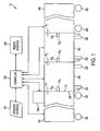
- a modular production apparatus for forming insulated rotor conductors suitable for immediate assembly into a rotor assembly for an alternating current generator in accordance with the present invention is shown diagrammatically, referred to generally by reference numeral 10.
- the apparatus comprises a movable infeed/affixing module 100, a dispensing device 100A attached to the infeed/affixing module 100, a bonding module 200, a conditioning module 300, and a movable collection module 400.
- the infeed/affixing module 100, the bonding module 200, the conditioning module 300 and the collection module 400 are shown connected together in a condition suitable for forming the insulated rotor conductors defining the production apparatus 10.
- the infeed/affixing module 100, bonding module 200, conditioning module 300 and collection module 400 are configured to be easily connected together to provide a continuous processing apparatus and easily disconnected from one another to enable relocation and maintenance as desired for use in a dynamic production environment.
- the infeed/affixing module 100 is configured to align with and connect to the bonding module 200 at a first interface I 1 .
- the conditioning module 300 is configured to align with and connect to the bonding module 200 at a second interface I 2 .
- the collection module 400 is configured to align with and connect to the conditioning module 300 at a third interface I 3 .
- the infeed/affixing module 100 may be provided with wheels 102 facilitating movement of the infeed/affixing module 100 relative to the other modules of the production apparatus 10 so as to enable easy transport of a plurality of electrical conductors from a remote location to the production apparatus 10 as will be described more thoroughly herein. Additionally, the collection module 400 may also be provided with wheels 402 to enable easy transport of a plurality of finished insulated rotor conductors from the production apparatus 10 to a remote location as will be described more thoroughly herein.
- the infeed/affixing module 100 and the collection module 400 as illustrated in Figs. 1 and 1A are provided with wheels 102 and 402, respectively, it is understood that other structure enabling easy transport of the infeed/affixing module 100 and collection module 400, e.g., provision for transport by fork lift truck or lifting by overhead means, may be utilized in other embodiments of the present invention.
- the bonding module 200 and the conditioning module 300 are provided with support structures 202 and 302, respectively, rather than wheels but wheels or other supporting structure such as provision for transport by a fork lift truck may be provided in other embodiments.
- the dispensing device 100A may be configured to couple with the infeed/affixing module 100 and/or the bonding module 200 and further to align with the infeed/affixing module 100 as will be described more thoroughly herein.
- the infeed/affixing module 100 comprises a movable cart 104 having a front side 106, a rear side 108, a first side 110, a second side 112, a bottom side 114 and a positioning structure 116.
- the infeed/affixing module 100 may be provided with a plurality of wheels 102 attached to or near to the bottom side 114 to enable easy movement of the infeed/affixing module 100 along a floor surface in a manufacturing facility.
- the wheels 102 comprise caster wheels to enable steering of the infeed/affixing module 100.
- a first alignment device comprising first and second portions A1 a , A1 b is provided in which the first portion A1 a , illustrated as a protrusion, is located on the second side 112 of the infeed/affixing module 100 and is configured to cooperate with the second portion A1 b , illustrated as a recess, positioned on a first side 230 of the bonding module 200 that is proximate to the infeed/affixing module 100 such that the infeed/affixing module 100 may be aligned with the bonding module 200 at the first interface I 1 , see Fig. 1 .
- a first attachment device F 1 is configured to cooperate with or proximate to the first side 230 of the bonding module 200 that is proximate to the second side 112 of the infeed/affixing module 200 such that the infeed/affixing module 100 may be fixedly attached to the bonding module 200 in a condition suitable for operation at the first interface I 1 , see Fig. 1 .
- a generally U-shaped channel 118 defining a feed reservoir 120 for receiving and storing a plurality of substantially straight electrical conductors 122 stacked vertically one atop another.
- the electrical conductors 122 have a predetermined length dimension and a predetermined width dimension.
- the feed reservoir 120 has a width dimension W in a direction 124 corresponding to the predetermined width dimension of the electrical conductors 122 stored therein.
- a structure (not shown), for example, an adjustable structure, may be provided to enable adjustment of the width dimension W such that the feed reservoir 120 may be adjusted to receive and store a plurality of electrical conductors 122 having one of a plurality of predetermined width dimensions.
- the width dimension W in the infeed/affixing module 100 illustrated in Fig. 1 A may be configured to accept a plurality of electrical conductors 122 having a predetermined width dimension within a range of from about 0.8 inch to about 2.0 inches.
- the feed reservoir 120 further has a length dimension M in a process direction P corresponding to a predetermined length dimension of the plurality of electrical conductors 122 stored therein.
- the length dimension M in the infeed/affixing module 100 illustrated in Fig. 2 may be configured to accept a plurality of electrical conductors having a predetermined length dimension within a range of from about 10 feet to about 30 feet.
- a moveable first supporting structure 128 configured to move in a vertical direction Y is positioned within the feed reservoir 120 to support the plurality of electrical conductors 122 stored therein.
- the first supporting structure 128 is configured to move toward the bottom side 114 in the direction Y a distance corresponding to a predetermined thickness of the electrical conductor 122 when the electrical conductor 122 is placed onto the first supporting structure 128.
- the first supporting structure 128 is configured to move vertically upwardly away from the bottom side 114 a distance corresponding to the predetermined thickness of the electrical conductor 122 when the electrical conductor 122 is removed from the feed reservoir.
- the first supporting structure 128 may comprise, for example, a spring biased device, a gas cylinder device, a hydraulic cylinder device, an indexing device, etc.
- a spring structure diagrammatically illustrated as 129, may be provided having a spring rate that causes the supporting structure 128 to move downwardly the thickness of one electrical conductor 122 each time an electrical conductor 122 is placed onto the supporting structure 128.
- the infeed/affixing module illustrated in Fig. 1 A is configured to receive a plurality of electrical conductors having a predetermined thickness dimension within a range of from about 0.1 inch to about 0.5 inch.
- the positioning structure 116 includes the horizontal surface 130 as previously mentioned.
- the horizontal surface 130 is positioned adjacent to the feed reservoir 120 and substantially coplanar with a bottom surface of the top-most electrical conductor 122 positioned atop the plurality of electrical conductors 122 within the feed reservoir 120.
- the positioning structure 116 further comprises a guide rail 132 extending upwardly substantially at a right angle from the horizontal surface 130 in the direction Y away from the bottom side 114.
- the guide rail 132 includes a vertical surface 134 configured to align the electrical conductor 122 as will be described more thoroughly herein.
- a positioning device 136 shown diagrammatically in Fig. 1 A , coupled to the infeed affixing module 100 may be provided to move the electrical conductor 122 from the feed reservoir 120 and position it upon the horizontal surface 130 adjacent to the guide rail 132 and in contact with the vertical surface 134 such that the electrical conductor 122 is properly positioned at a first position for application of an insulating material as will be described herein.
- the positioning device 136 may comprise, for example, a pneumatic cylinder operated device, an electromechanical operated device or other apparatus as is well known to those skilled in the art. Alternatively, a human operator may manually move the electrical conductor 122 from the feed reservoir 120 and into position at the first position on the horizontal surface 130.
- the dispensing device 100A (not shown in Fig. 1 A) may be coupled to the infeed affixing module 100 proximate to the bonding module 200, see Figs. 1 and 2 .
- structures generally illustrated as 138 and 140 may be provided coupled to the guide rail 132 for aligning and coupling the dispensing device 100A to the infeed/affixing module 100.
- the dispensing device 100A may be coupled to the infeed/affixing module 100 proximate to the bonding module 200 and in alignment with the electrical conductor 122 positioned adjacent to the guide rail 132 at the first position such that the insulating material may be dispensed from the dispensing module 100A and onto the electrical conductor 122 as will be described herein.
- a guiding device may be provided for engaging a front side 142 of the electrical conductor 122 and for applying a biasing force between the electrical conductor 122 and the vertical surface 134 of the guide rail 132 such that the electrical conductor 122 remains in contact with the guide rail 132 as the electrical conductor 122 is conveyed past the dispensing device 100A and from the infeed/affixing module 100 and into the bonding module 200. In this fashion, the electrical conductor 122 remains in alignment with the dispensing device 100A as the insulating material is dispensed from the dispensing device 100A and onto the electrical conductor 122.
- the guiding device (not shown) in the infeed/affixing module 100 illustrated in Fig.
- 1A may be adjustable such that the guiding device (not shown) may be preset to accept an electrical conductor 122 having one of a plurality of predetermined width dimensions within a range of from about 0.8 inch to about 2.0 inches. Further the guiding device (not shown) may be incorporated as a guide structure on the positioning device 136.
- the infeed/affixing module 100 is shown attached to the bonding module 200. Also shown is the dispensing device 100A attached to the infeed/affixing module 100 proximate to the bonding module 200. As illustrated in Fig, 2 , the dispensing device 100A comprises a structure 102A for mounting a reel 104A containing a continuously wound strip of insulating material 106A.
- the insulating material preferably comprises a substrate formed of an epoxy glass laminate having a thickness of approximately 0.008 to 0.015 inch, and having a layer of heat activated or thermo-set adhesive having a thickness of approximately 0.0005 to 0.0020 inch.
- the structure 102A may comprise a rotating spindle about which the reel 104A rotates as the insulating material 106A is dispensed onto a electrical conductor 122 moving horizontally beneath in the process direction P forming a layered conductor structure 110A having an insulating surface 112A and a conducting surface 114A.
- An affixing roller 116A is provided adjacent to the upper surface of the electrical conductor 122 to guide the insulating material 106A to a predetermined position onto the upper surface of the electrical conductor 122 as the layered conductor structure 110A is conveyed into the bonding module 200.
- a cutting device illustrated diagrammatically as 109, may be provided as part of or adjacent to the dispensing device 100A.
- the cutting device 109 may include a knife 109A actuated at predetermined times corresponding to a gap between successive ones of the electrical conductors 122 to form discrete strips of the insulating material substantially corresponding in length to the length of the electrical conductors 122.
- a tensioning device may be provided to maintain tension in the portion of the insulating material 106A that is unwound from the reel 104A before it is affixed to the electrical conductor 122 by the affixing roller 116A.
- the tensioning device may comprise a friction brake or other suitable means to control rotation of the reel 104A as the strip of insulating material 106A is unwound from the reel 104A as the insulating material 106A moves into engagement with the electrical conductor 122.
- the insulating material 106A may be pre-cut into strips of a predetermined length corresponding to the length of the electrical conductors 122.
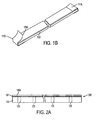
- the insulating material 106A is preferably held in place by means of strips of Teflon ® tape 111 A, 111 B wrapped around the end portions of the insulating material 106A and the electrical conductor 122. This is illustrated in Fig. 1B where the Teflon ® tape strip 111 A is shown in position wrapped around one end of the insulating material 106A and the electrical conductor 122, and the Teflon ® tape strip 111 B is shown partially wrapped around the opposite end, i.e., in the process of being wrapped around the end.
- An operation performed in this embodiment may involve an operator manually placing a pre-cut strip of insulating material 106A on an electrical conductor 122, and applying the strips of Teflon ® tape 111 A and 111B to the ends thereof at the infeed/affixing module 100 prior to transfer of the assembled insulating material 106A and electrical conductor 122 into the bonding module 200.
- the step of moving individual ones of the electrical conductors 122 from the feed reservoir 120 to the aligned position adjacent the guide rail 132 may be performed manually.
- the support structure 128 moves each successive electrical conductor 122 to a vertical position that is convenient for an operator to slide it across the horizontal surface 130 to the guide rail 132.
- the first attachment device F 1 may be detached from the infeed/affixing module 100 and the bonding module 200 to permit detachment of the infeed/affixing module 100 from the production apparatus 10.
- a plurality of infeed/affixing modules 100 may be provided such that another infeed/affixing module 100 containing another plurality of electrical connectors 122 may be positioned in alignment with the bonding module 200 and attached thereto in order to continue manufacturing insulated rotor conductors with only a brief interruption of the process.
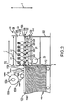
- a bonding module 200 in accordance with the present invention is illustrated in diagrammatic side cut-away view attached to the infeed/affixing module 100 with the dispensing device 100A attached thereto.
- the bonding module 200 comprises a supporting structure 202 upon which an enclosure 204 is mounted.
- the enclosure 204 defines a box-shaped chamber 206 within which a layered conductor structure 208 being conveyed therethrough in the process direction P is heated to a predetermined bonding temperature, i.e., a predetermined minimum temperature, and a predetermined compressive pressure is applied to the opposite sides of the layered conductor structure 208 forming an insulated rotor conductor as will be described more thoroughly herein.
- the enclosure 204 comprises an entry side 210 having a first aperture 212 therein defining an entry slot through which layered conductor structures 208 are conveyed from the infeed/affixing module 100 and into the bonding module 200.
- a cylindrically-shaped first entry roller 214 and a cylindrically-shaped second entry roller 216 are positioned adjacent to one another and define an entry nip 218 therebetween for grasping a layered conductor structure 208 entering the aperture 212 from the infeed/affixing module 100.
- the first entry roller 214 and the second entry roller 216 preferably comprise rubber coated rollers having axes (not shown) extending in a direction substantially perpendicular to the process direction P.
- the space between the first entry roller 214 and the second entry roller 216 in the direction Y may be adjustable so that the entry nip 218 may be configured to accept a layered conductor structure 208 having a predetermined thickness in the direction Y.
- One or both of the first entry roller 214 and the second entry roller 216 is driven to rotate in a direction such that the layered conductor structure 208 grasped within the entry nip 218 is caused to move in the process direction P.
- a rotational driver for example, a first electric motor 215, may be coupled to one or both of the first entry roller 214 and the second entry roller 216 such that layered conductor structure 208 may be conveyed through the entry nip 218 and into the bonding module 200 at a predetermined conveying velocity.
- a plurality of cylindrically-shaped transport rollers 220 are arranged within the enclosure 204 adjacent to and parallel with one another and defining a planar conveying structure upon which the layered conductor structure 208 is supported as it is conveyed through the bonding module 200.
- the transport rollers 220 have axes (not shown) extending in a direction substantially perpendicular to the process direction P.
- the transport rollers 220 have bearings (not shown) therein and are mounted on shafts (not shown) such that the transport rollers 220 may rotate freely about the shafts (not shown).
- the plurality of transport rollers 220 and the entry nip 218 defined by the first entry roller 214 and the second entry roller 216 comprise a conveying device for conveying the layered conductor structure 208 into and through the bonding module 200.
- the transport rollers 220 may be made from a material such as, for example, stainless steel, and the bearings (not shown) used in the transport rollers 220 may be high temperature bearings.
- a plurality of cylindrically-shaped pressure rollers 222 are arranged adjacent to and parallel with one another and on an opposite side of the layered conductor structure 208 from the transport rollers 220 such that the layered conductor structure 208 moving through the bonding module 200 is contacted on opposite sides by the transport rollers 220 and the pressure rollers 222.
- the pressure rollers 222 include bearings (not shown) mounted on shafts having axes extending in a direction substantially perpendicular to the process direction P.
- the pressure rollers 222 in the bonding module 200 illustrated in Fig. 2 may be made from a material such as, for example, steel or aluminum, and may have a rubber coating applied to an exterior circumferential surface.
- the pressure rollers 222 may include an adjustment mechanism 221 for adjusting the pressure rollers in the vertical direction Y relative to the transport rollers 220, see Fig. 2 .
- the pressure rollers 222 may be adjusted so as to accept layered conductor structures having a predetermined thickness dimension comprising the combined thickness of the electrical conductor 122 and the insulating material 106A.
- the adjustment mechanism 221 for the pressure rollers 222 may comprise, for example, a spring biased device, a hydraulic cylinder biased device, an air cylinder biased device, etc., such that the pressure rollers 222 in cooperation with the transport rollers 220 may apply a predetermined compressive pressure between the opposite sides of an insulated conductor structure 208 moving between the plurality of transport rollers 220 and the plurality of pressure rollers 222.
- the predetermined compressive pressure may be within a range of from about 40 psi to about 400 psi and the compressive pressure is preferably set at or close to the lowest value necessary to enable bonding between the insulating material 106A and the electrical conductor 122, as is described further below.
- a heating device 224 is provided within the enclosure 204 for heating the insulated conductor structure 208 moving therethrough to a predetermined minimum temperature such that the insulating material 106A affixed to the electrical conductor 122, see Fig. 2 , is bonded to the electrical conductor 122.
- the heating device 224 is configured to heat the portion of the insulated conductor structure 208 that is within the confines of the enclosure 204 to the predetermined minimum temperature while the predetermined compressive pressure is being applied to the opposite sides of the insulated conductor structure 208 as previously described.
- the insulating material 106A is preferably provided with a layer of heat activated adhesive 107 on a lower surface thereof for engagement with the electrical conductor 122, see Fig. 2A .
- the heat activated adhesive may comprise a B-staged adhesive.
- the lower surface of the insulating material 106A may be coated, either continuously or discontinuously at discrete locations, with an adhesive which generally may comprise an epoxy, phenolic, epoxy-phenolic, or other suitable resin, which is in the "B" stage thermoset adhesive catetgory.
- the adhesive comprises either an epoxy or nitrile-phenolic rubber resin.
- the B-staged adhesive is tack-free at ambient temperature and becomes soft and thus flows at elevated temperatures and then permanently sets to adhesively bond the adjacent layers of the insulated conductor 208 into a solid unit.
- the predetermined compressive pressure maintains the insulating material 106A in contact with the electrical conductor 122 while the insulated conductor structure 208 is heated to the predetermined minimum temperature to cause the B-staged adhesive to bond the insulating material 106A to the electrical conductor 122 forming an insulated rotor conductor 308, see Figs. 2 and 2A .
- the insulated rotor conductor 308 generally comprises a section of the adhesively bonded insulating material 106A and electrical conductor 122, i.e., a bonded leading end section of the insulated conductor structure 208, or comprises the entire insulated conductor structure 208 that has passed through the bonding module 200 and that has been converted into a solid unit by adhesive bonding of the insulating material 106A to the electrical conductor 122.
- the heating device 224 may comprise at least one of a convection heating device, a radiant heating device and an induction heating device.
- the predetermined minimum temperature used in the bonding module 200 illustrated in Fig. 2 may be within a range of from about 400 degrees F to about 600 degrees F.
- the bonding module 200 has a length selected to provide a sufficient dwell time for the adhesive to be activated for bonding the insulating material 106A to the electrical conductor 122.
- the length L of the bonding module 200 is less than 6 feet in the process direction P, and most preferably, the length L is approximately 3-5 feet to minimize the use of manufacturing facility space.
- the enclosure 204 also comprises an exit side having a second aperture 226 therein defining a slot through which the insulated rotor conductor 308 is conveyed in the process direction P from the bonding module 200 and into the conditioning module 300, see also Fig. 1 .
- a first cooling device 228 may be positioned within the enclosure 204 adjacent to the second aperture 226 to cool the insulated rotor conductor 308 moving through the second aperture 226.
- the first cooling device 228 may comprise one or more nozzles for directing a flow of cooling fluid, for example, compressed air, onto one or more surfaces of the insulated rotor conductor 308 moving through the second aperture 226. In this fashion, the insulated rotor conductor 308 may be cooled a first amount before entering the conditioning module 300, see Figs. 1 and 2 .
- the bonding module 200 has a second side 232 positioned proximate to the conditioning module 300.
- a second alignment device may be optionally positioned on the second side 232 of the bonding module 200.
- the second alignment device may comprise first and second portions A2 a and A2 b , in which the first portion A2 a , illustrated as a protrusion, is located on the second side 232 of the bonding module 200 and is configured to cooperate with the second portion A2 b , illustrated as a recess, positioned on a first side 310 of the conditioning module 300 proximate to the bonding module 200 such that the conditioning module 300 may be aligned with the bonding module 200 at the second interface I 2 , see Figs. 1 and 3 .
- a second attachment device F 2 is provided to cooperate between the second side 232 of the bonding module 200 and the first side 310 of the conditioning module 300.
- the bonding module 200 may be fixedly attached to the conditioning module 300 at the second interface I 2 in a condition suitable for operation, see Figs. 1 and 3 .
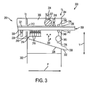
- the conditioning module 300 in accordance with the present invention is illustrated in diagrammatic cut-away side view connected to the bonding module 200 at the second interface I 2 .
- the conditioning module 300 comprises a support structure 302 upon which an enclosure 304 is mounted.
- the enclosure 304 defines a chamber 306 within which an insulated rotor conductor 308 being conveyed therethrough in the process direction P is preferably cooled to a predetermined maximum temperature as will be described more thoroughly herein.
- the enclosure 304 comprises a first aperture 312 located at the first side 310 and defines a slot through which the insulated rotor conductor 308 is conveyed from the bonding module 200 and into the chamber 306.
- a second cooling device 314 Positioned within the chamber 306 is a second cooling device 314 configured to cool the insulated rotor conductor 308 a second amount to a predetermined maximum temperature while the insulated rotor conductor 308 remains within the chamber 306.
- the second cooling device 314 in the illustrated conditioning module 300 comprises a plurality of nozzles 316 configured to direct a flow of cooling fluid, for example, compressed air onto one or more surfaces of the insulated rotor conductor 308 being conveyed through the conditioning module 300.
- the electrical conductors 122 may be formed with a plurality of apertures 123, such as oval apertures extending through the electrical conductor 122, see Fig. 2A .
- the insulating material 106A that is affixed to the electrical conductor 122 at the infeed/affixing module 100 may or may not have corresponding apertures pre-cut into the insulating material 106A.
- the apertures 123 in the electrical conductor 122 may be covered by the insulating material 106A.
- a cylindrically-shaped pressure roller 322 is positioned adjacent the upper surface of the insulated rotor conductor 308 within the chamber 306, downstream from the second cooling device 314.
- the pressure roller 322 is supported on bearings and on a shaft (not shown) that has an axis oriented substantially perpendicular to the process direction P.
- the pressure roller 322 is coupled to a second pressure application device 324, for example, a spring biased device or, preferably, a hydraulic cylinder biased device that is configured to apply a second compressive pressure to the pressure roller 322 toward the insulated rotor conductor 308 in the direction Y.
- the pressure roller 322 preferably comprises a rubber roller and the second pressure application device 324 causes the pressure roller 322 to apply a second compressive pressure between an exterior circumferential surface of the pressure roller 322 and the insulated rotor conductor 308 to cause the insulating material 106A to be punched downwardly through the apertures 123 in the electrical conductor 122, thereby forming loose, released portions of the insulating material 106A.
- a debris removing device 318 is positioned adjacent to and downstream from the pressure roller 322, in the process direction P, see Fig. 3 .
- the debris removing device 318 is configured to provide a high pressure stream of air, such as a stream of air at approximately 90 psi, to blow debris 309 comprising the loose, released portions of insulating material 106A from the location of the apertures 123 downwardly away from the insulated rotor conductor 308.
- the chamber 306 further comprises a cavity 326 into which the insulating material debris 309 falls and is collected.
- a lower side 328 of the enclosure 304 defines a floor of the cavity 326.
- a discharge aperture 330 is positioned on or near the lower side 328 of the enclosure 304.
- the discharge aperture 330 defines a coupling 332 to which a vacuum source (not shown) may be coupled such that the insulating material debris 309 may be removed from the cavity 326 where it has collected.
- the enclosure 304 further comprises a second or exit side 334 having a second aperture 336, defining an exit slot through which the insulated rotor conductor 308 is conveyed in the process direction P from the conditioning module 300 and into the collection module 400, see Figs. 1 and 3 .
- First and second cylindrically-shaped exit rollers 338, 340 are positioned within the enclosure 304 proximate to the second aperture 336.
- the first and second exit rollers 338, 340 are supported for rotation about axes (not shown) extending in a direction substantially perpendicular to the process direction P.
- the first exit roller 338 is configured to engage with the insulating side 321 of the insulated rotor conductor 308, and the second exit roller 340 is configured to engage with the conducting side 320 of the insulated rotor conductor 308.
- the first exit roller 338 and the second exit roller 340 are positioned relative to one another in the vertical direction Y so as to define an exit nip 342 therebetween for grasping the insulated rotor conductor 308 between the first and second exit rollers 338 and 340.
- the spacing between the first exit roller 338 and the second exit roller 340 in the direction Y may be adjustable so that the exit nip 342 may accept a layered conductor structure 308 having a predetermined thickness.
- One or both of the first exit roller 338 and the second entry roller 340 is caused to rotate in a direction such that the insulated rotor conductor 308 grasped within the exit nip 342 is caused to move toward the exit side 334 in the process direction P.
- a rotational driver for example, a second electric motor 343, may be coupled to one or both of the first exit roller 338 and the second exit roller 340 such that the insulated rotor conductor 308 may be conveyed through the exit nip 342 and further through the third aperture 336 and into the collection module 400, see Figs. 1 and 3 .
- the first exit roller 338 and the second exit roller 340 are synchronized with the first entry roller 214 and the second entry roller 216 within the bonding module 200, see Fig. 2 , such that the insulated rotor conductor 308 is conveyed through the exit nip 342, see Fig. 3 , at substantially the same predetermined conveying velocity as the layered conductor structure 208 is conveyed through the entry nip 218, see Fig. 2 .
- first and second entry rollers 214, 216 operate in cooperation with the first and second exit rollers 338, 340, and in combination with the plurality of transport rollers 220, and the first and second electric motors 215, 343 comprise a conveying device for conveying the layered conductor structure 208 into and through the bonding module 200 and the insulated rotor conductor 308 into and through the conditioning module 300 and further into the collection module 400 at the predetermined conveying velocity, see Figs. 1 , 2 and 3 .
- the predetermined conveying velocity may be within a range of from about 1 foot per minute to about 20 feet per minute.
- the distance between the first and second entry rollers 214, 216 and the first and second exit rollers 338, 340 is less than the length of an electrical conductor 122 to be conveyed from the infeed/affixing module 100 and through the apparatus 10.
- at least one of the pairs of entry rollers 214, 216 or exit rollers 338, 340 will be engaged with the layered conductor structure 208/insultated rotor conductor 308 at all times as it passes through the apparatus 10.
- a third alignment device is positioned on the second side 334 of the conditioning module 300.
- the third alignment device may comprise first and second portions A3 a , A3 b , in which the first portion A3 a , illustrated as a recess, is located on the second side 334 of the conditioning module 300 and is configured to cooperate with the second portion A3 b , illustrated as a protrusion, positioned on a first side 410 of the collection module 400 proximate to the conditioning module 300 such that the collection module 400 may be aligned with the conditioning module 300 at the third interface I 3 , see Figs. 1 and 4 .
- a third attachment device F 3 is provided to cooperate between the second side 334 of the conditioning module 300 and the first side 410 of the collection module 400.
- the conditioning module 300 may be fixedly attached to the collection module 400 at the third interface I 3 in a condition suitable for operation, see Figs. 1 and 4 .
- a collection module 400 in accordance with the present invention is illustrated diagrammatically in partial perspective view.
- the collection module 400 is configured to collect a plurality of insulated rotor conductors 308 conveyed from the conditioning module 300 and to transport the plurality of insulated rotor conductors 308 to a remote location.
- the illustrated collection module 400 comprises a movable cart 404 having a front side 406, a rear side 408, a first side 410, a second side 412, a bottom side 414 and a collection structure 416.
- the collection module 400 may be provided with a plurality of wheels 402 attached to or near to a surface of the bottom side 414 to enable easy movement of the collection module along a floor surface in a manufacturing facility.
- the wheels 402 may comprise caster wheels to enable steering of the collection module 400.
- the collection structure 416 includes a horizontal surface 420 configured to receive an insulated rotor conductor 308 as it is conveyed from the conditioning module 300.
- the horizontal surface 420 is positioned a small spaced distance toward the bottom side 414 in the vertical direction Y from the conducting surface 320 of the insulated rotor conductor 308 as it is conveyed from the conditioning module 300.
- the insulated rotor conductor 308 is supported upon and moves along the horizontal surface 420 in the process direction P as the insulated rotor conductor 308 is conveyed from the conditioning module 300. Further, the insulated rotor conductor 308 comes to rest upon the horizontal surface 420 after it is fully conveyed from the conditioning module 300.
- the collection structure 416 further comprises a guide rail 422 extending perpendicularly upwardly substantially at a right angle from the horizontal surface 420.
- the guide rail 422 has a vertical surface 424 configured to guide the insulated rotor conductor 308 substantially in the process direction P as it is conveyed from the conditioning module 300 and onto the horizontal surface 420 and to prevent movement of the insulated rotor conductor 308 away from the front side 406 in the direction 124 beyond the vertical surface 424.
- the distance M' substantially corresponds to the length of the insulated rotor conductors 308 to be collected within the collection reservoir 428.
- the collection module 400 may have a length dimension M' configured to receive insulated rotor conductors 308 having a predetermined length dimension within a range of from about 10 feet to about 30 feet.
- the collection reservoir 428 has a width dimension W' extending in the direction 124 that is configured to accommodate insulated rotor conductors 308 having a predetermined width dimension.
- the width dimension W' may be sized to accommodate insulated rotor conductors 308 having one of a plurality of predetermined width dimensions within a range of from about 0.8 inch to about 2.0 inches.
- an adjustable structure (not shown) may be provided configured to enable adjustment of the width dimension W' such that the collection reservoir 428 may be pre-adjusted to accept a plurality of insulated rotor conductors 308 having one of a plurality of predetermined width dimensions.
- a moveable second supporting structure 434 configured to move in the vertical direction Y is positioned within the collection reservoir 428 to support the insulated rotor conductors 308 collected therein.
- the second supporting structure 434 is configured to move toward the bottom side 414 a distance corresponding to the thickness of the insulated rotor conductor 308 when an insulated rotor conductor 308 is placed into the collection reservoir 428. That is, the weight of each insulated rotor conductor 308 will cause the supporting structure to move vertically downwardly a distance equal to the thickness of one insulated rotor conductor 308.
- the second supporting structure 434 is further configured to move away from the bottom side 414 a distance corresponding to the thickness of the insulated rotor conductor 308 when the insulated rotor conductor 308 is removed from the collection reservoir 428. In this fashion, a plurality of insulated rotor conductors 308 may be collected and stored one atop the previous one in the collection reservoir 428.
- the second supporting structure 434 may comprise, for example, a spring biased device, a gas cylinder device, a hydraulic cylinder device, an indexing device, etc.
- a spring structure diagrammatically illustrated as 418, may be provided having a spring rate that causes the supporting structure to move downwardly the thickness of one insulated rotor conductor 308 each time an insulated rotor conductor 308 is placed into the supporting structure 434.
- the collection structure 416 further comprises a surface 436 extending at an angle from the horizontal surface 420 to a first wall 438 of the collection reservoir 428 thereby defining a ramp 440 upon which the insulated rotor conductor 308 may be moved from the horizontal surface 420 into the collection reservoir 428.
- a surface 436 extending at an angle from the horizontal surface 420 to a first wall 438 of the collection reservoir 428 thereby defining a ramp 440 upon which the insulated rotor conductor 308 may be moved from the horizontal surface 420 into the collection reservoir 428.
- the conditioning module 300 cools the insulated rotor conductors 308 sufficiently that they may be safely handled by an operator.
- the temperature of the insulated rotor conductor 308 may be decreased to approximately 100 degrees F as they exit the conditioning module 300.
- a plurality of insulated rotor conductors 308 may be placed into the collection reservoir 428 one atop the previous one until the collection reservoir 428 is filled substantially to capacity. Subsequently, the collection module 400 may be disconnected from the conditioning module 300 by releasing the third attachment device F 3 , see Fig. 1 . The collection module 400 may now be moved to a remote location such that the plurality of insulated rotor conductors 308 contained therein may be further processed or stored.
- a plurality of collection modules 400 may be provided such that another collection module 400 may now be positioned in alignment with the conditioning module 300 and attached thereto as previously described in order to continue manufacturing insulated rotor conductors with only a minimal interruption of the process.
- the modular apparatus further comprises a controller 500 coupled to the infeed/affixing module 100, the dispensing device 100A, the bonding module 200, the conditioning module 300 and the collection module 400.
- the controller 500 may comprise, for example, a programmable logic controller, a microcomputer, a personal computer, etc. or other processing device as is well known those skilled in the art.
- the controller 500 may be configured to control functions of the modular production apparatus 10 including, for example, the positioning device 136, see Fig. 1A , the dispensing device 100A, see Fig, 2 , the tensioning device (not shown), the heating device 224, see Fig, 2 , the first pressure application device 221, the first cooling device 228, the second cooling device 316, see Fig, 3 , the debris removing device 318, the second pressure application device 324, and the conveying device.
- An operator interface 510 may be coupled to the controller 500 to enable a human operator to enter values corresponding to at least one of a predetermined operating temperature for the bonding module 200, predetermined compressive pressures within the bonding module 200 and conditioning module 300, and a predetermined conveying velocity for the entry and exit roller pairs 214, 216 and 338, 340.
- a remote interface 520 may be connected to the controller 500 to enable connection to a remote processing device (not shown) such that the controller 500 may be controlled by the remote processing device (not shown) from a remote location.
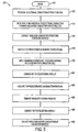
- a flow diagram 600 of the steps of the present invention is illustrated.
- the process illustrated in Fig. 5 may be a continuous iterative process beginning at step 610.
- an electrical conductor 122 is removed from the feed reservoir 120 and positioned at the first position in preparation for application of the insulating material 106A thereto.
- step 614 the insulating material 106A is affixed at one side of the electrical conductor 122 at the infeed/affixing module 100 forming an insulated conductor structure (ICS) 208.
- ICS insulated conductor structure
- step 616 the insulated conductor structure (ICS) 208 is conveyed from the infeed/affixing module 100 to the bonding module 200.
- ICS insulated conductor structure
- step 618 the insulated conductor structure (ICS) 208 is heated to a predetermined bonding temperature within the bonding module 200.
- step 620 a predetermined compressive pressure is applied between the opposite sides of the insulated conductor structure (ICS) 208 ensuring contact between the insulating material 106A and the electrical conductor 122 via the heated layer of adhesive 107 within the bonding module 200 forming an insulated rotor conductor (IRC) 308.
- ICS insulated conductor structure
- step 622 the insulated rotor conductor (IRC) 308 is conveyed to the conditioning module 300.
- step 624 the insulated rotor conductor (IRC) 308 is cooled to a predetermined maximum temperature by the second cooling device 316 within the conditioning module 300.
- IRC insulated rotor conductor
- step 626 insulating material debris 309 is removed from the insulated rotor conductor (IRC) 308 by the debris removing device 318 within the conditioning module 300.
- IRC insulated rotor conductor
- step 628 the insulated rotor conductor (IRC) 308 is conveyed from the conditioning module 300 to the collection module 400.
- IRC insulated rotor conductor
- step 630 the insulted rotor conductor (IRC) 308 is collected and stored within the collection reservoir 428 in the collection module 400.
- the process may be performed successively until a desired number of insulated rotor conductors have been manufactured.
Landscapes
- Engineering & Computer Science (AREA)
- Power Engineering (AREA)
- Manufacturing & Machinery (AREA)
- Manufacture Of Motors, Generators (AREA)
- Heat Treatment Of Articles (AREA)
Claims (20)
- Vorrichtung (10) zur Formung isolierter Rotorleiter, die einen flachen elektrischen Leiter (122) mit einer mit ihm verklebten Schicht eines isolierenden Materials (106A) umfassen, dadurch gekennzeichnet, dass die besagte Vorrichtung eine Vielzahl von lösbar aneinander befestigten Modulen (100, 200, 300, 400) zum Transportieren der besagten Schicht eines isolierenden Materials und einzelner Leiter von den besagten elektrischen Leitern in einer Prozessrichtung (P) durch die besagten Module hindurch umfasst, wobei die besagten Module umfassen:ein Zuführungsmodul (100) zum Zuführen einzelner Leiter von den besagten elektrischen Leitern von einem Stapel elektrischer Leiter zu einer vorbestimmten ersten Position in dem besagten Zuführungsmodul;ein Verklebungsmodul (200), das dem besagten Zuführungsmodul benachbart ist, zum Verkleben einer Schicht des besagten isolierenden Materials mit den besagten elektrischen Leitern, um eine massive einheitliche Struktur zu formen, welche die besagten isolierten Rotorleiter definiert, wobei das besagte Verklebungsmodul umfasst:eine Heizkammer (206), die eine Heizvorrichtung (224) umschließt, zum Erhitzen der besagten elektrischen Leiter und der besagten Schicht eines isolierenden Materials auf eine vorbestimmte Temperatur, um dadurch die besagte Schicht eines isolierenden Materials mit den besagten einzelnen elektrischen Leitern zu verkleben;eine Zuführungsöffnung (212), die in einer Seite (210) der besagten Heizkammer ausgebildet ist und mit der besagten ersten Position fluchtet, zum Aufnehmen der besagten elektrischen Leiter und der besagten Schicht des besagten isolierenden Materials in der besagten Prozessrichtung;
undeine Austrittsöffnung (226), die in einer Seite der besagten Heizkammer ausgebildet ist und die der besagten Zuführungsöffnung gegenüberliegt und mit ihr fluchtet, zum Austragen der besagten isolierten Rotorleiter aus dem besagten Verklebungsmodul; undein Sammelmodul (400), das in der besagten Prozessrichtung stromabwärts des besagten Verklebungsmoduls angeordnet ist, zum Aufnehmen der besagten isolierten Rotorleiter, wobei das besagte Sammelmodul einen Sammelbehälter (428) zum Aufnehmen einer Vielzahl der besagten isolierten Rotorleiter in vertikal gestapelter Anordnung aufweist. - Vorrichtung nach Anspruch 1, wobei das besagte Zuführungsmodul (100) und das besagte Sammelmodul (400) bewegliche Wagen (104) umfassen, die auf Rollen (102, 402) gelagert sind, derart, dass das besagte Zuführungsmodul in einer Richtung zu der Seite der besagten Zuführungsöffnung des besagten Verklebungsmoduls hin und von ihr weg beweglich ist, und dass das besagte Sammelmodul in einer Richtung zu der Seite der besagten Austrittsöffnung des besagten Verklebungsmoduls hin und von ihr weg beweglich ist.
- Vorrichtung nach Anspruch 2, wobei das besagte Zuführungsmodul (100) und das besagte Sammelmodul (400) jeweils Ausrichtvorrichtungen (A1a, A3b) zum Eingriff an einem benachbarten Modul aufweisen, um das besagte Zuführungsmodul und das besagte Sammelmodul in der besagten Prozessrichtung auszurichten, wenn das besagte Zuführungsmodul und das besagte Sammelmodul auf den besagten Rollen in der besagten Richtung zu dem besagten Verklebungsmodul hin bewegt werden.
- Vorrichtung nach Anspruch 1, wobei ein Beschickungsbehälter (120) eine vorbestimmte Länge (M) in der besagten Prozessrichtung (P) aufweist, zum Einlagern elektrischer Leiter einer maximalen Länge, und das besagte Verklebungsmodul (200) eine Länge aufweist, welche kleiner als die besagte vorbestimmte Länge ist.
- Vorrichtung nach Anspruch 1, wobei die besagten Module ferner ein Konditioniermodul (300) aufweisen, das zwischen dem besagten Verklebungsmodul (200) und dem besagten Sammelmodul (400) angeordnet ist, wobei das besagte Konditioniermodul umfasst:eine Konditionierkammer (306), die eine Kühlvorrichtung (314) zum Abkühlen der besagten isolierten Rotorleiter auf eine vorbestimmte maximale Temperatur umschließt;eine Zuführungsöffnung (312), die in einer Seite (310) der besagten Konditionierkammer ausgebildet ist und mit der besagten Austrittsöffnung des besagten Verklebungsmoduls fluchtet; undeine Austrittsöffnung (336), die in einer Seite (334) der besagten Konditionierkammer ausgebildet ist und die der besagten Zuführungsöffnung der besagten Konditionierkammer gegenüberliegt und mit ihr fluchtet.
- Vorrichtung nach Anspruch 5, wobei das besagte Verklebungsmodul (200) ferner ein Paar Eintrittsrollen (214, 216), die der besagten Zuführungsöffnung (212) des besagten Verklebungsmoduls benachbart angeordnet sind, und einen Antriebsmotor (215) zum Antreiben der besagten Eintrittsrollen in einer Vorwärtsrichtung, um die besagte Schicht eines isolierenden Materials und einzelne elektrische Leiter von dem besagten Zuführungsmodul durch die besagte Heizkammer hindurch und in die besagte Konditionierkammer (300) hinein zu transportieren, aufweist.
- Vorrichtung nach Anspruch 6, wobei das besagte Konditioniermodul ferner ein Paar Austrittsrollen (338, 340), die der besagten Austrittsöffnung des besagten Konditioniermoduls benachbart angeordnet sind, und einen Antriebsmotor (343) zum Antreiben der besagten Austrittsrollen in einer Vorwärtsrichtung, um die besagten isolierten Rotorleiter von dem besagten Verklebungsmodul (200) durch die besagte Konditionierkammer (300) hindurch und in das besagte Sammelmodul (400) hinein zu transportieren, aufweist.
- Vorrichtung nach Anspruch 7, wobei ein Beschickungsbehälter (120) eine vorbestimmte Länge (M) in der besagten Prozessrichtung (P) aufweist, zum Aufnehmen elektrischer Leiter einer maximalen Länge, und ein Abstand zwischen den besagten Eintrittsrollen (214, 216) und den besagten Austrittsrollen (338, 340) kleiner als die besagte vorbestimmte Länge ist.
- Vorrichtung nach Anspruch 5, wobei die besagte Kühlvorrichtung (314) eine Zwangsluft-Kühlvorrichtung (316) zum Blasen von Kühlluft über den besagten isolierten Rotorleiter innerhalb der besagten Konditionierkammer umfasst.
- Vorrichtung nach Anspruch 5, wobei der besagte elektrische Leiter eine Vielzahl von Löchern (123) umfasst und das besagte Konditioniermodul ferner eine Andruckrolle (322) aufweist, die mit dem besagten isolierten Rotorleiter in Eingriff gelangt, um das besagte isolierende Material (106A) in die besagten Löcher zu pressen und dabei einen losen, gelösten Teil des besagten isolierenden Materials zu bilden.
- Vorrichtung nach Anspruch 10, wobei das besagte Konditioniermodul ferner eine Abfallbeseitigungsvorrichtung (318) aufweist, die einen Zwangsluftstrom umfasst, der auf den besagten isolierten Rotorleiter gerichtet ist, um den besagten losen, gelösten Teil (309) des besagten isolierenden Materials (106A) von dem besagten isolierten Rotorleiter weg und in einen Hohlraum (326) hinein, der in einem unteren Abschnitt (328) des besagten Konditioniermoduls ausgebildet ist, zu blasen.
- Vorrichtung nach Anspruch 1, wobei das besagte Zuführungsmodul (100) ferner einen Beschickungsbehälter (120) zum Einlagern einer Vielzahl der besagten elektrischen Leiter in vertikal gestapelter Anordnung und eine Positionierstruktur (116) zum Ausrichten einzelner Leiter von den besagten elektrischen Leitern aus dem besagten Beschickungsbehälter in der besagten vorbestimmten ersten Position umfasst.
- Vorrichtung nach Anspruch 12, wobei das besagte Zuführungsmodul (100) einen vertikal beweglichen Träger (128) umfasst, der innerhalb des besagten Beschickungsbehälters (120) angeordnet ist, wobei der besagte vertikal bewegliche Träger so gelagert ist, dass er sich um einen Abstand nach oben bewegt, der im Wesentlichen gleich mindestens einer vertikalen Dicke eines der besagten elektrischen Leiter ist, wenn ein am weitesten oben befindlicher elektrischer Leiter von der besagten Vielzahl elektrischer Leiter in vertikal gestapelter Anordnung entnommen wird.
- Vorrichtung nach Anspruch 1, wobei das besagte Sammelmodul (400) einen vertikal beweglichen Träger (434) umfasst, der innerhalb des besagten Sammelbehälters angeordnet ist, wobei der besagte vertikal bewegliche Träger so gelagert ist, dass er sich um einen Abstand nach unten bewegt, der im Wesentlichen gleich mindestens einer vertikalen Dicke eines der besagten isolierten Rotorleiter ist, wenn ein am weitesten oben befindlicher isolierter Rotorleiter zu der besagten Vielzahl isolierter Rotorleiter in vertikal gestapelter Anordnung hinzugefügt wird.
- Verfahren zur Formung eines isolierten Rotorleiters, der einen flachen elektrischen Leiter (122) mit einer mit ihm verklebten Schicht eines isolierenden Materials (106A) umfasst, in einer Vorrichtung (10), die eine Vielzahl von lösbar aneinander befestigten Modulen (100, 200, 300, 400) zum Transportieren der besagten Schicht eines isolierenden Materials und einzelner Leiter von den besagten elektrischen Leitern in einer Prozessrichtung (P) durch die besagten Module hindurch umfasst, wobei das besagte Verfahren die folgenden Schritte umfasst:Bereitstellen einer Vielzahl der besagten elektrischen Leiter (122) auf einem Zuführungsmodul (100);Bereitstellen einer Schicht eines isolierenden Materials (106A) für einzelne Leiter von den besagten elektrischen Leitern (122) auf dem besagten Zuführungsmodul (100);Transportieren jedes besagten elektrischen Leiters (122) mit einer Schicht eines isolierenden Materials (106A) von dem besagten Zuführungsmodul (100) zu einem Verklebungsmodul (200), das dem besagten Zuführungsmodul (100) benachbart angeordnet ist;Erhitzen jedes besagten elektrischen Leiters (122) mit einer Schicht eines isolierenden Materials (106A) innerhalb des besagten Verklebungsmoduls (200), um einen durch Wärme aktivierten Klebstoff (107) auf einer Fläche des besagten isolierenden Materials zu aktivieren, um die besagte Schicht eines isolierenden Materials mit dem besagten elektrischen Leiter zu verkleben und dadurch einen isolierten Rotorleiter zu formen; undTransportieren jedes besagten isolierten Rotorleiters von dem besagten Verklebungsmodul zu einem Sammelmodul (400), wo eine Vielzahl der besagten isolierten Rotorleiter eingelagert wird.
- Verfahren nach Anspruch 15, wobei der besagte Schritt des Bereitstellens einer Schicht eines isolierenden Materials (106A) für einzelne Leiter von den besagten elektrischen Leitern (122) das Anbringen eines vorgeschnittenen Streifens des besagten isolierenden Materials auf dem besagten elektrischen Leiter umfasst, wobei der besagte vorgeschnittene Streifen eine Länge hat, welche im Allgemeinen einer Länge des besagten elektrischen Leiters entspricht.
- Verfahren nach Anspruch 16, wobei der besagte Schritt des Bereitstellens einer Schicht eines isolierenden Materials (106A) für einzelne Leiter von den besagten elektrischen Leitern (122) ferner den Schritt des Befestigens gegenüberliegender Längsenden der besagten Schicht eines isolierenden Materials an dem besagten elektrischen Leiter durch Anwendung diskreter Befestigungselemente an den besagten Längsenden umfasst.
- Verfahren nach Anspruch 15, welches ferner den Schritt des Transportierens jedes besagten isolierten Rotorleiters durch ein Konditioniermodul (300) zwischen dem besagten Verklebungsmodul und dem besagten Sammelmodul umfasst, wobei das besagte Konditioniermodul eine Kühlvorrichtung (314) zum aktiven Kühlen des besagten isolierten Rotorleiters aufweist.
- Verfahren nach Anspruch 18, wobei das besagte Sammelmodul (400) zu einer Verbindung mit dem besagten Konditioniermodul (300) hin und von ihr weg beweglich ist und das besagte Sammelmodul (400) einen Sammelbehälter (428) umfasst, in den eine Vielzahl der besagten isolierten Rotorleiter in vertikal gestapelter Anordnung eingelagert ist, und wenn einzelne Rotorleiter von den besagten isolierten Rotorleitern zu dem besagten Sammelmodul transportiert werden und dem besagten Sammelbehälter zugeführt werden, ein Träger (434) innerhalb des besagten Sammelbehälters bewirkt, dass sich der besagte Stapel um einen Abstand nach unten bewegt, der im Wesentlichen gleich einer vertikalen Dicke eines der besagten isolierten Rotorleiter ist.
- Verfahren nach Anspruch 15, wobei das besagte Zuführungsmodul (100) zu einer Verbindung mit dem besagten Verklebungsmodul (200) hin und von ihr weg beweglich ist und das besagte Zuführungsmodul einen Beschickungsbehälter (120) umfasst, in den eine Vielzahl der besagten elektrischen Leiter in vertikal gestapelter Anordnung eingelagert ist, und wenn einzelne Leiter von den besagten elektrischen Leitern aus dem besagten Beschickungsbehälter entnommen werden, ein Träger (128) innerhalb des besagten Beschickungsbehälters bewirkt, dass sich der besagte Stapel um einen Abstand nach oben bewegt, der im Wesentlichen gleich einer vertikalen Dicke eines der besagten elektrischen Leiter ist.
Applications Claiming Priority (3)
| Application Number | Priority Date | Filing Date | Title |
|---|---|---|---|
| US97385707P | 2007-09-20 | 2007-09-20 | |
| US12/031,074 US8037915B2 (en) | 2007-09-20 | 2008-02-14 | Method and apparatus for forming insulated rotor conductors |
| PCT/US2008/010475 WO2009038648A1 (en) | 2007-09-20 | 2008-09-08 | Method and apparatus for forming insulated rotor conductors |
Publications (2)
| Publication Number | Publication Date |
|---|---|
| EP2201667A1 EP2201667A1 (de) | 2010-06-30 |
| EP2201667B1 true EP2201667B1 (de) | 2011-03-16 |
Family
ID=40094433
Family Applications (1)
| Application Number | Title | Priority Date | Filing Date |
|---|---|---|---|
| EP08831299A Not-in-force EP2201667B1 (de) | 2007-09-20 | 2008-09-08 | Verfahren und vorrichtung zur formung isolierter rotorleiter |
Country Status (7)
| Country | Link |
|---|---|
| US (1) | US8037915B2 (de) |
| EP (1) | EP2201667B1 (de) |
| CN (1) | CN101803155B (de) |
| AT (1) | ATE502429T1 (de) |
| DE (1) | DE602008005627D1 (de) |
| RU (1) | RU2408966C1 (de) |
| WO (1) | WO2009038648A1 (de) |
Families Citing this family (2)
| Publication number | Priority date | Publication date | Assignee | Title |
|---|---|---|---|---|
| US8623226B2 (en) | 2012-04-12 | 2014-01-07 | Eastman Kodak Company | Making stacked pancake motors using patterned adhesives |
| CN103001402A (zh) * | 2012-11-20 | 2013-03-27 | 甘肃酒钢集团宏兴钢铁股份有限公司 | 处理电机定子齿压板松动的绑扎法 |
Family Cites Families (22)
| Publication number | Priority date | Publication date | Assignee | Title |
|---|---|---|---|---|
| JPS423327B1 (de) | 1963-04-01 | 1967-02-13 | ||
| JPS513097B1 (de) * | 1970-09-21 | 1976-01-31 | ||
| US3915203A (en) * | 1970-11-23 | 1975-10-28 | Solo Products Corp | Plastic-jacketed article and method of making the same |
| US3881907A (en) * | 1974-01-30 | 1975-05-06 | Ppg Industries Inc | Method of tempering glass sheets |
| US4263475A (en) | 1974-12-23 | 1981-04-21 | General Electric Company | Dynamoelectric machine insulators |
| JPS5238101A (en) | 1975-09-19 | 1977-03-24 | Hitachi Ltd | Interstage paper feed device |
| US4389584A (en) | 1979-02-01 | 1983-06-21 | General Electric Company | Dynamoelectric machine phase insulators and apparatus for making the same |
| AT378613B (de) * | 1980-04-11 | 1985-09-10 | Sticht Walter | Programmierbare einrichtung zur steuerung bzw. ueberwachung von antrieben an einer arbeitsmaschine |
| DE3024036A1 (de) * | 1980-06-26 | 1982-01-14 | Rutishauser Data AG, 8712 Stäfa | Transportvorrichtung fuer blattfoermige aufzeichnungstraeger |
| CH677565A5 (de) | 1988-11-10 | 1991-05-31 | Asea Brown Boveri | |
| US5164142A (en) | 1991-09-20 | 1992-11-17 | Westinghouse Electric Corp. | Stepmolding process and apparatus |
| US6387184B1 (en) * | 1998-01-09 | 2002-05-14 | Fastar, Ltd. | System and method for interchangeably interfacing wet components with a coating apparatus |
| JP3809033B2 (ja) | 1999-06-18 | 2006-08-16 | 株式会社東芝 | 絶縁物貼り付け装置 |
| IT1313118B1 (it) | 1999-08-25 | 2002-06-17 | Morton Int Inc | Apparecchiatura di applicazione a vuoto dotata di mezzi trasportatorie procedimento per applicare un resist a film secco ad un pannello |
| DE19963491A1 (de) * | 1999-12-28 | 2001-07-05 | Alstom Power Schweiz Ag Baden | Verfahren zur Herstellung einer hochwertigen Isolierung von elektrischen Leitern oder Leiterbündeln rotierender elektrischer Maschinen mittels Sprühsintern |
| DE19963492A1 (de) * | 1999-12-28 | 2001-07-05 | Alstom Power Schweiz Ag Baden | Verfahren zur Herstellung einer hochwertigen Isolierung von elektrischen Leitern oder Leiterbündeln rotierender elektrischer Maschinen mittels thermischen Spritzens |
| RU2002120492A (ru) * | 1999-12-28 | 2004-04-20 | Альстом | Способ получения высококачественной изоляции для электрических проводников или пучков проводников для вращающихся электрических машин методом термического напыления |
| US6912443B2 (en) * | 2000-03-10 | 2005-06-28 | David W. Duemler | Modular automated assembly system |
| JP4718758B2 (ja) * | 2000-07-28 | 2011-07-06 | ハイパーカー,インコーポレイテッド | 先進的複合構造体の製造方法及び装置 |
| US6498415B1 (en) | 2000-09-06 | 2002-12-24 | Siemens Westinghouse Power Corporation | High voltage stator coil having low loss insulator and electrode covering and method therefor |
| JP2002329965A (ja) * | 2001-05-07 | 2002-11-15 | New Create Kk | 薄膜積層体の製造方法および製造装置 |
| US6663816B2 (en) | 2002-01-31 | 2003-12-16 | General Electric Company | Method of making a dynamoelectric machine conductor bar and method of making a conductor bar dynamoelectric machine |
-
2008
- 2008-02-14 US US12/031,074 patent/US8037915B2/en not_active Expired - Fee Related
- 2008-09-08 AT AT08831299T patent/ATE502429T1/de not_active IP Right Cessation
- 2008-09-08 WO PCT/US2008/010475 patent/WO2009038648A1/en not_active Ceased
- 2008-09-08 CN CN2008801078843A patent/CN101803155B/zh not_active Expired - Fee Related
- 2008-09-08 DE DE602008005627T patent/DE602008005627D1/de active Active
- 2008-09-08 EP EP08831299A patent/EP2201667B1/de not_active Not-in-force
- 2008-09-08 RU RU2010115492/07A patent/RU2408966C1/ru not_active IP Right Cessation
Also Published As
| Publication number | Publication date |
|---|---|
| CN101803155A (zh) | 2010-08-11 |
| US20090078369A1 (en) | 2009-03-26 |
| DE602008005627D1 (de) | 2011-04-28 |
| CN101803155B (zh) | 2013-02-06 |
| WO2009038648A1 (en) | 2009-03-26 |
| US8037915B2 (en) | 2011-10-18 |
| RU2408966C1 (ru) | 2011-01-10 |
| EP2201667A1 (de) | 2010-06-30 |
| ATE502429T1 (de) | 2011-04-15 |
Similar Documents
| Publication | Publication Date | Title |
|---|---|---|
| CN105579221B (zh) | 用于制造先进复合部件的方法和系统 | |
| CN109435225B (zh) | 一种自动穿烘热缩套管机 | |
| KR102098091B1 (ko) | 전선 자동 바인딩 포장장치 | |
| US5876654A (en) | Method for shaping honeycomb core | |
| EP2201667B1 (de) | Verfahren und vorrichtung zur formung isolierter rotorleiter | |
| US20110072643A1 (en) | Transformer Core Assembly Apparatus | |
| CN111422396B (zh) | 一种薄膜包装装置及薄膜包装方法 | |
| CN117226923A (zh) | 加工装置 | |
| CN101741187A (zh) | 接合线圈绕线方法和接合线圈绕线装置 | |
| CN104210693A (zh) | 一种专用于胶合板的贴膜装置 | |
| JP3336185B2 (ja) | 積層体の製造方法及びその装置 | |
| CN219180624U (zh) | 裹胶设备 | |
| EP3762232B1 (de) | Vorschubwellenübergangsvorrichtung und ausrüstung zum heissfolienprägen und stanzen | |
| JP2005515900A (ja) | プラスチック積層体の冷間プレス連続製造装置 | |
| CN116408335A (zh) | 废铜箔卷快速剥离装置及其使用方法 | |
| CN205833951U (zh) | 一种铜箔软连接自动加工装置 | |
| CN110255277B (zh) | 一种铺纸机 | |
| CN204056375U (zh) | 一种专用于胶合板的贴膜装置 | |
| KR20240114252A (ko) | 초고속 진공 튜브 열차 레일용 적층체 제조장치 | |
| US4944671A (en) | Method and apparatus for storing and dispensing environmentally sensitive materials | |
| JP4722547B2 (ja) | 電圧変成器コイルの巻線装置 | |
| KR20140004375A (ko) | 단열 패드 절단장치 | |
| CN119764053B (zh) | 一种电动恒张力箔绕机 | |
| CN223821219U (zh) | 一种瓦楞纸热压贴合设备 | |
| CN110570996B (zh) | 一种高频数据线缆及其制造工艺、生产设备 |
Legal Events
| Date | Code | Title | Description |
|---|---|---|---|
| PUAI | Public reference made under article 153(3) epc to a published international application that has entered the european phase |
Free format text: ORIGINAL CODE: 0009012 |
|
| 17P | Request for examination filed |
Effective date: 20100218 |
|
| AK | Designated contracting states |
Kind code of ref document: A1 Designated state(s): AT BE BG CH CY CZ DE DK EE ES FI FR GB GR HR HU IE IS IT LI LT LU LV MC MT NL NO PL PT RO SE SI SK TR |
|
| AX | Request for extension of the european patent |
Extension state: AL BA MK RS |
|
| GRAP | Despatch of communication of intention to grant a patent |
Free format text: ORIGINAL CODE: EPIDOSNIGR1 |
|
| DAX | Request for extension of the european patent (deleted) | ||
| GRAS | Grant fee paid |
Free format text: ORIGINAL CODE: EPIDOSNIGR3 |
|
| GRAA | (expected) grant |
Free format text: ORIGINAL CODE: 0009210 |
|
| AK | Designated contracting states |
Kind code of ref document: B1 Designated state(s): AT BE BG CH CY CZ DE DK EE ES FI FR GB GR HR HU IE IS IT LI LT LU LV MC MT NL NO PL PT RO SE SI SK TR |
|
| REG | Reference to a national code |
Ref country code: GB Ref legal event code: FG4D |
|
| REG | Reference to a national code |
Ref country code: CH Ref legal event code: EP |
|
| REG | Reference to a national code |
Ref country code: IE Ref legal event code: FG4D |
|
| REF | Corresponds to: |
Ref document number: 602008005627 Country of ref document: DE Date of ref document: 20110428 Kind code of ref document: P |
|
| REG | Reference to a national code |
Ref country code: DE Ref legal event code: R096 Ref document number: 602008005627 Country of ref document: DE Effective date: 20110428 |
|
| REG | Reference to a national code |
Ref country code: NL Ref legal event code: VDEP Effective date: 20110316 |
|
| PG25 | Lapsed in a contracting state [announced via postgrant information from national office to epo] |
Ref country code: NO Free format text: LAPSE BECAUSE OF FAILURE TO SUBMIT A TRANSLATION OF THE DESCRIPTION OR TO PAY THE FEE WITHIN THE PRESCRIBED TIME-LIMIT Effective date: 20110616 Ref country code: HR Free format text: LAPSE BECAUSE OF FAILURE TO SUBMIT A TRANSLATION OF THE DESCRIPTION OR TO PAY THE FEE WITHIN THE PRESCRIBED TIME-LIMIT Effective date: 20110316 Ref country code: LT Free format text: LAPSE BECAUSE OF FAILURE TO SUBMIT A TRANSLATION OF THE DESCRIPTION OR TO PAY THE FEE WITHIN THE PRESCRIBED TIME-LIMIT Effective date: 20110316 Ref country code: SE Free format text: LAPSE BECAUSE OF FAILURE TO SUBMIT A TRANSLATION OF THE DESCRIPTION OR TO PAY THE FEE WITHIN THE PRESCRIBED TIME-LIMIT Effective date: 20110316 Ref country code: GR Free format text: LAPSE BECAUSE OF FAILURE TO SUBMIT A TRANSLATION OF THE DESCRIPTION OR TO PAY THE FEE WITHIN THE PRESCRIBED TIME-LIMIT Effective date: 20110617 Ref country code: ES Free format text: LAPSE BECAUSE OF FAILURE TO SUBMIT A TRANSLATION OF THE DESCRIPTION OR TO PAY THE FEE WITHIN THE PRESCRIBED TIME-LIMIT Effective date: 20110627 Ref country code: LV Free format text: LAPSE BECAUSE OF FAILURE TO SUBMIT A TRANSLATION OF THE DESCRIPTION OR TO PAY THE FEE WITHIN THE PRESCRIBED TIME-LIMIT Effective date: 20110316 |
|
| LTIE | Lt: invalidation of european patent or patent extension |
Effective date: 20110316 |
|
| PG25 | Lapsed in a contracting state [announced via postgrant information from national office to epo] |
Ref country code: SI Free format text: LAPSE BECAUSE OF FAILURE TO SUBMIT A TRANSLATION OF THE DESCRIPTION OR TO PAY THE FEE WITHIN THE PRESCRIBED TIME-LIMIT Effective date: 20110316 Ref country code: FI Free format text: LAPSE BECAUSE OF FAILURE TO SUBMIT A TRANSLATION OF THE DESCRIPTION OR TO PAY THE FEE WITHIN THE PRESCRIBED TIME-LIMIT Effective date: 20110316 Ref country code: CY Free format text: LAPSE BECAUSE OF FAILURE TO SUBMIT A TRANSLATION OF THE DESCRIPTION OR TO PAY THE FEE WITHIN THE PRESCRIBED TIME-LIMIT Effective date: 20110316 Ref country code: AT Free format text: LAPSE BECAUSE OF FAILURE TO SUBMIT A TRANSLATION OF THE DESCRIPTION OR TO PAY THE FEE WITHIN THE PRESCRIBED TIME-LIMIT Effective date: 20110316 Ref country code: BG Free format text: LAPSE BECAUSE OF FAILURE TO SUBMIT A TRANSLATION OF THE DESCRIPTION OR TO PAY THE FEE WITHIN THE PRESCRIBED TIME-LIMIT Effective date: 20110616 |
|
| PG25 | Lapsed in a contracting state [announced via postgrant information from national office to epo] |
Ref country code: BE Free format text: LAPSE BECAUSE OF FAILURE TO SUBMIT A TRANSLATION OF THE DESCRIPTION OR TO PAY THE FEE WITHIN THE PRESCRIBED TIME-LIMIT Effective date: 20110316 |
|
| PG25 | Lapsed in a contracting state [announced via postgrant information from national office to epo] |
Ref country code: EE Free format text: LAPSE BECAUSE OF FAILURE TO SUBMIT A TRANSLATION OF THE DESCRIPTION OR TO PAY THE FEE WITHIN THE PRESCRIBED TIME-LIMIT Effective date: 20110316 Ref country code: PT Free format text: LAPSE BECAUSE OF FAILURE TO SUBMIT A TRANSLATION OF THE DESCRIPTION OR TO PAY THE FEE WITHIN THE PRESCRIBED TIME-LIMIT Effective date: 20110718 |
|
| PG25 | Lapsed in a contracting state [announced via postgrant information from national office to epo] |
Ref country code: IS Free format text: LAPSE BECAUSE OF FAILURE TO SUBMIT A TRANSLATION OF THE DESCRIPTION OR TO PAY THE FEE WITHIN THE PRESCRIBED TIME-LIMIT Effective date: 20110716 Ref country code: SK Free format text: LAPSE BECAUSE OF FAILURE TO SUBMIT A TRANSLATION OF THE DESCRIPTION OR TO PAY THE FEE WITHIN THE PRESCRIBED TIME-LIMIT Effective date: 20110316 Ref country code: RO Free format text: LAPSE BECAUSE OF FAILURE TO SUBMIT A TRANSLATION OF THE DESCRIPTION OR TO PAY THE FEE WITHIN THE PRESCRIBED TIME-LIMIT Effective date: 20110316 Ref country code: CZ Free format text: LAPSE BECAUSE OF FAILURE TO SUBMIT A TRANSLATION OF THE DESCRIPTION OR TO PAY THE FEE WITHIN THE PRESCRIBED TIME-LIMIT Effective date: 20110316 |
|
| PG25 | Lapsed in a contracting state [announced via postgrant information from national office to epo] |
Ref country code: NL Free format text: LAPSE BECAUSE OF FAILURE TO SUBMIT A TRANSLATION OF THE DESCRIPTION OR TO PAY THE FEE WITHIN THE PRESCRIBED TIME-LIMIT Effective date: 20110316 |
|
| PLBE | No opposition filed within time limit |
Free format text: ORIGINAL CODE: 0009261 |
|
| STAA | Information on the status of an ep patent application or granted ep patent |
Free format text: STATUS: NO OPPOSITION FILED WITHIN TIME LIMIT |
|
| 26N | No opposition filed |
Effective date: 20111219 |
|
| PG25 | Lapsed in a contracting state [announced via postgrant information from national office to epo] |
Ref country code: PL Free format text: LAPSE BECAUSE OF FAILURE TO SUBMIT A TRANSLATION OF THE DESCRIPTION OR TO PAY THE FEE WITHIN THE PRESCRIBED TIME-LIMIT Effective date: 20110316 Ref country code: DK Free format text: LAPSE BECAUSE OF FAILURE TO SUBMIT A TRANSLATION OF THE DESCRIPTION OR TO PAY THE FEE WITHIN THE PRESCRIBED TIME-LIMIT Effective date: 20110316 |
|
| REG | Reference to a national code |
Ref country code: DE Ref legal event code: R097 Ref document number: 602008005627 Country of ref document: DE Effective date: 20111219 |
|
| PG25 | Lapsed in a contracting state [announced via postgrant information from national office to epo] |
Ref country code: MC Free format text: LAPSE BECAUSE OF NON-PAYMENT OF DUE FEES Effective date: 20110930 |
|
| REG | Reference to a national code |
Ref country code: IE Ref legal event code: MM4A |
|
| PG25 | Lapsed in a contracting state [announced via postgrant information from national office to epo] |
Ref country code: IE Free format text: LAPSE BECAUSE OF NON-PAYMENT OF DUE FEES Effective date: 20110908 |
|
| PG25 | Lapsed in a contracting state [announced via postgrant information from national office to epo] |
Ref country code: MT Free format text: LAPSE BECAUSE OF FAILURE TO SUBMIT A TRANSLATION OF THE DESCRIPTION OR TO PAY THE FEE WITHIN THE PRESCRIBED TIME-LIMIT Effective date: 20110316 |
|
| REG | Reference to a national code |
Ref country code: CH Ref legal event code: PL |
|
| PG25 | Lapsed in a contracting state [announced via postgrant information from national office to epo] |
Ref country code: LU Free format text: LAPSE BECAUSE OF NON-PAYMENT OF DUE FEES Effective date: 20110908 |
|
| PG25 | Lapsed in a contracting state [announced via postgrant information from national office to epo] |
Ref country code: LI Free format text: LAPSE BECAUSE OF NON-PAYMENT OF DUE FEES Effective date: 20120930 Ref country code: CH Free format text: LAPSE BECAUSE OF NON-PAYMENT OF DUE FEES Effective date: 20120930 |
|
| PG25 | Lapsed in a contracting state [announced via postgrant information from national office to epo] |
Ref country code: TR Free format text: LAPSE BECAUSE OF FAILURE TO SUBMIT A TRANSLATION OF THE DESCRIPTION OR TO PAY THE FEE WITHIN THE PRESCRIBED TIME-LIMIT Effective date: 20110316 |
|
| PG25 | Lapsed in a contracting state [announced via postgrant information from national office to epo] |
Ref country code: HU Free format text: LAPSE BECAUSE OF FAILURE TO SUBMIT A TRANSLATION OF THE DESCRIPTION OR TO PAY THE FEE WITHIN THE PRESCRIBED TIME-LIMIT Effective date: 20110316 |
|
| REG | Reference to a national code |
Ref country code: FR Ref legal event code: PLFP Year of fee payment: 8 |
|
| PGFP | Annual fee paid to national office [announced via postgrant information from national office to epo] |
Ref country code: GB Payment date: 20150909 Year of fee payment: 8 |
|
| PGFP | Annual fee paid to national office [announced via postgrant information from national office to epo] |
Ref country code: FR Payment date: 20150910 Year of fee payment: 8 |
|
| PGFP | Annual fee paid to national office [announced via postgrant information from national office to epo] |
Ref country code: IT Payment date: 20150924 Year of fee payment: 8 |
|
| PGFP | Annual fee paid to national office [announced via postgrant information from national office to epo] |
Ref country code: DE Payment date: 20151120 Year of fee payment: 8 |
|
| REG | Reference to a national code |
Ref country code: DE Ref legal event code: R119 Ref document number: 602008005627 Country of ref document: DE |
|
| GBPC | Gb: european patent ceased through non-payment of renewal fee |
Effective date: 20160908 |
|
| REG | Reference to a national code |
Ref country code: FR Ref legal event code: ST Effective date: 20170531 |
|
| PG25 | Lapsed in a contracting state [announced via postgrant information from national office to epo] |
Ref country code: DE Free format text: LAPSE BECAUSE OF NON-PAYMENT OF DUE FEES Effective date: 20170401 Ref country code: FR Free format text: LAPSE BECAUSE OF NON-PAYMENT OF DUE FEES Effective date: 20160930 Ref country code: GB Free format text: LAPSE BECAUSE OF NON-PAYMENT OF DUE FEES Effective date: 20160908 |
|
| PG25 | Lapsed in a contracting state [announced via postgrant information from national office to epo] |
Ref country code: IT Free format text: LAPSE BECAUSE OF NON-PAYMENT OF DUE FEES Effective date: 20160908 |