EP2201739B1 - Access technology indication for proxy mobile internet protocol - Google Patents
Access technology indication for proxy mobile internet protocol Download PDFInfo
- Publication number
- EP2201739B1 EP2201739B1 EP08804911.9A EP08804911A EP2201739B1 EP 2201739 B1 EP2201739 B1 EP 2201739B1 EP 08804911 A EP08804911 A EP 08804911A EP 2201739 B1 EP2201739 B1 EP 2201739B1
- Authority
- EP
- European Patent Office
- Prior art keywords
- prefix
- mobile node
- interface
- mobility
- access
- Prior art date
- Legal status (The legal status is an assumption and is not a legal conclusion. Google has not performed a legal analysis and makes no representation as to the accuracy of the status listed.)
- Active
Links
Images

Classifications
-
- H—ELECTRICITY
- H04—ELECTRIC COMMUNICATION TECHNIQUE
- H04W—WIRELESS COMMUNICATION NETWORKS
- H04W60/00—Affiliation to network, e.g. registration; Terminating affiliation with the network, e.g. de-registration
- H04W60/005—Multiple registrations, e.g. multihoming
-
- H—ELECTRICITY
- H04—ELECTRIC COMMUNICATION TECHNIQUE
- H04L—TRANSMISSION OF DIGITAL INFORMATION, e.g. TELEGRAPHIC COMMUNICATION
- H04L61/00—Network arrangements, protocols or services for addressing or naming
- H04L61/50—Address allocation
- H04L61/5046—Resolving address allocation conflicts; Testing of addresses
-
- H—ELECTRICITY
- H04—ELECTRIC COMMUNICATION TECHNIQUE
- H04L—TRANSMISSION OF DIGITAL INFORMATION, e.g. TELEGRAPHIC COMMUNICATION
- H04L2101/00—Indexing scheme associated with group H04L61/00
- H04L2101/60—Types of network addresses
- H04L2101/618—Details of network addresses
- H04L2101/659—Internet protocol version 6 [IPv6] addresses
-
- H—ELECTRICITY
- H04—ELECTRIC COMMUNICATION TECHNIQUE
- H04W—WIRELESS COMMUNICATION NETWORKS
- H04W80/00—Wireless network protocols or protocol adaptations to wireless operation
- H04W80/04—Network layer protocols, e.g. mobile IP [Internet Protocol]
-
- H—ELECTRICITY
- H04—ELECTRIC COMMUNICATION TECHNIQUE
- H04W—WIRELESS COMMUNICATION NETWORKS
- H04W88/00—Devices specially adapted for wireless communication networks, e.g. terminals, base stations or access point devices
- H04W88/02—Terminal devices
- H04W88/06—Terminal devices adapted for operation in multiple networks or having at least two operational modes, e.g. multi-mode terminals
Definitions
- This invention is related to the area of IP Mobility.
- the Internet Engineering Task Force IETF
- IP Proxy Mobile Internet Protocol version 6
- PMIP6 Proxy Mobile Internet Protocol version 6
- 3GPP Third Generation Partnership Protocol
- 3GPP2 Third Generation Partnership Protocol2
- a mobile node When a mobile node (MN) has multiple interfaces (for example, Institute for Electrical and Electronics Engineers (IEEE) 802.11a/b/g or generally referred to as Wireless Fidelity (WiFi), Global System for Mobile Communications (GSM), Enhanced Data rates for Global Evolution (EDGE), Wideband Code Division Multiple Access (WCDMA), High-Speed Packet Access (HSPA), IEEE 802.16e, General Packet Radio Services (GPRS), Third Generation (3G), or the like) it is possible for the MN to attach, via these interfaces, to the appropriate access networks simultaneously.
- a 3G MN may be connected to the Universal Mobile Telecommunications System (UMTS) packet core as well as being connected to the WiFi/802.11 network at the same time.
- UMTS Universal Mobile Telecommunications System
- the MN would be attached to the Mobility Access Gateways (MAG) in these networks.
- MAG Mobility Access Gateways
- the MAG sends a Proxy Binding Update (PBU) to the Local Mobility Agent/ Anchor (LMA).
- PBU Proxy Binding Update
- LMA Local Mobility Agent/ Anchor
- the identifier used in the PBU can be a common identifier across the 3G and WiFi networks.
- An example of such an identifier is a Network Access Identifier (NAI).
- LMA Local Mobility Agent
- PBUs Proxy Binding Updates
- a first way is by indicating the access network technology type in the PBU by the MAG to the LMA.
- a second way is by indicating the Interface Identification (ID) of the MN to the LMA in the PBU if it is available to the MAG.
- ID Interface Identification
- the MAG When the MN attaches to the MAG and completes access authentication, the MAG will send a PBU (Proxy Binding Update) to the LMA, which contains the MN-ID.
- PBU Proxy Binding Update
- Two new options can be added to the PBU as a solution for dealing with multi-interface hosts that attach to MAGs in access networks that are served by the same LMA.
- Access network type can indicate whether the access network by which the MN is attached to the MAG is of a certain technology type.
- Examples of access network type include: GPRS, UMTS, High Speed Packet Access (HSPA), Long Term Evolution (LTE), Evolution Data Optimized (EV-DO), Code Division Multiple Access (CDMA) version 1X (CDMAIX), Worldwide Interoperability for Microwave Access (WiMAX), Institute for Electrical and Electronics Engineers (IEEE) 802.11a/b/g, and the like.
- the MN can include the Interface ID in the Proxy Binding Update.
- a new parameter proposed herein for carrying the Interface ID is an "MN-Interface-ID.”
- the LMA that receives the information about either the access technology type or the interface ID from a MAG, is able to process it and determine that the PBU sent by the MAG is for an MN that may already have a binding cache entry on another interface, i.e. is for an MN that is attaching via a different interface to the network.
- the LMA can then assign a different prefix to the MN and respond via the PBAck message.
- FIG. 1 illustrates a system in which a MN is attached to multiple access networks at the same time via its interfaces.
- an LMA may need to differentiate the fact that the PBUs are from the same MN but from different access networks.
- the LMA may accomplish this objective by looking at the Access Technology (AT) field or the Interface ID (IID) field in the PBU message.
- AT Access Technology
- IID Interface ID
- an MN which has interfaces I1, I2 and 13, attaches via Interface I1 to an LTE network.
- MAG1 in the LTE network sends a PBU to the assigned LMA on behalf of the MN.
- the MN-ID field in the PBU in this example, is set to: MN@operatorX.com (for example).
- the MAG1 inserts an Interface ID if it is aware of the MNs Interface ID (IID), and otherwise it leaves the MN-Interface-ID field empty (or set to 0).
- the LMA assigns a prefix, P1, to the MN and sends the prefix via PBAck to MAG1.
- the MN attaches via a WiFi interface, 12, to an 802.11g network that has PMIP6 capability.
- MAG2 in the 802.11g network that the MN is attached to sends a PBU to the LMA on behalf of the MN.
- the MN-ID field in the PBU is, in this example, set to: MN@operatorX.com (example).
- the Access Network Type field in the PBU in this example is set to: 802.11g.
- MAG2 inserts an Interface ID if it is aware of the MNs IID, and otherwise it leaves the MN-Interface-ID field empty (or set to 0).
- the LMA that receives the PBU from MAG2 processes it and notes that the MN-ID field is the same for which it already has assigned a prefix, and that the MN-ID field exists in the binding cache.
- the LMA can recognize that the access network type from which the PBU was sent is different by parsing the Access Network type field. It can also realize that the Interface by which the MN is attaching to the network is different if the Interface ID field was available in both PBUs received from MAG1 and MAG2.
- the LMA can then choose a different prefix, P2, and assign it to the MN, sending prefix P2 to MAG2 in the PBAck.
- the prefix in step (6) can be Prefix P1 if the LMA is aware that the MN is capable of handling the same prefix or if the LMA is aware of the MN having a virtual interface for the interfaces that are being used by the MN to connect to the two networks.
- the LMA can also have a policy that would allow the LMA to recognize the capability of an MN attaching to the LMA via MAG2 and assign Prefix P1 itself in the PBAck.
- the MN can receive prefix P2 via a router advertisement from MAG2 on Interface 12.
- the MN can create an address from Prefix P2 (using stateless address autoconfiguration) and can associate that address to interface 12.
- the LMA can be aware of which prefix to assign to an MN because of the awareness that the PBU for the MN (with a common ID) is coming from a different interface/access network. Accordingly, the solution may be relatively uncomplicated to implement, as it may be implemented, for example, by extending the PBU with two new parameters, and employing appropriate processing in the MN, MAGs, and LMA. Certain advantages of the described embodiments include that they can help to solve the issues associated with MNs that have multiple interfaces and can attach simultaneously via these interfaces.
- the LMA needs to be able to differentiate the fact that the PBUs are from the same MN but from different interfaces.
- the LMA on seeing the PBU with the same NAI but with a different access technology indication or interface identifier could assign a unique prefix via the PBAck, where the unique prefix does not conflict with the prefix assigned to another interface.
- This solution would enable an MN to attach to different MAGs that are in different access networks of differing technologies and not cause conflicts in prefix assignment or confuse the LMA into thinking that the MN had performed a handover (HO).
- This solution may be useful, for example, for interworking between LTE and High Rate Packet Data (HRPD)/Evolution Data Optimized (EV-DO) or between WiMAX and HRPD, or in other similar situations.
- HRPD High Rate Packet Data
- EV-DO Evolution Data Optimized
- WiMAX WiMAX
- HRPD High Rate Packet Data
- HRPD High Rate Packet Data
- EV-DO Evolution Data Optimized
- WiMAX WiMAX and HRPD
- FIG. 3 illustrates a system according to an embodiment of the present invention.
- the system can include a mobile node (MN) 310, a plurality of mobility access gateways (MAGs) 320, 330, and 340 (additional MAGs may be included, but are not illustrated, for simplicity), and a local mobility anchor or agent (LMA) 350.
- MN mobile node
- MAGs mobility access gateways
- LMA local mobility anchor or agent
- the LMA 350 can include a receiving unit 352 configured to receive data from external devices, a processing unit 354 configured to process received data and prepare data to be sent, and a sending unit 356 configured to send data to external devices.
- Each of the units 352, 354, and 356 can be, for example, implemented using software running on computer hardware such as a general purpose computer or an application specific integrated circuit.
- the LMA 350 can also include a memory 358 for storing data.
- the memory 358 can be either internal or external to LMA 350. Examples of memories include hard drives, flash Random Access Memory (RAM), and Compact Disc Read Only Memory (CD-ROM).
- a first MAG 320 can be configured to function as an interface.
- the MAG 320 can include a preparing unit 324 configured to prepare an access individuated indicator, such as an access technology indication or an interface identifier.
- the MAG 320 can include a sending unit 326 configured to send data to external devices and a receiving unit 322 configured to receive data from external devices.
- Each of the units 322, 324, and 326 can be, for example, implemented using software running on computer hardware such as a general purpose computer or an application specific integrated circuit.
- the MAG 320 can include a memory 328 for storing data. Examples of memories include hard drives, flash Random Access Memory (RAM), and Compact Disc Read Only Memory (CD-ROM).
- MAGS 330 and 340 are not shown, but can be similar to MAG 320. There is no need, however, for MAGS 330 and 340 to be the same as MAG 320, and consequently MAGS 330 and 340 can vary considerably from MAG 320, each of MAGS 320, 330, and 340 serving to operate in accordance with, for example, a different communication standard from one another.
- the MN 310 can including an attaching unit 316 configured to attach to a plurality of interfaces, and to send data to external devices.
- the MN 310 can also include a processing unit 314 configured to prepare attachment and data to be sent, as well as data received or stored in memory.
- the MN 310 can further include a receiving unit 312 configured to receive data from external devices.
- Each of the units 312, 314, and 316 can be, for example, implemented using software running on computer hardware such as a general purpose computer or an application specific integrated circuit.
- the MN 310 can include a memory 318 for storing data. Examples of memories include hard drives, flash Random Access Memory (RAM), and Compact Disc Read Only Memory (CD-ROM).
- the MN 310 can communicate with one or more of the MAGs 320, 330, and 340 using a communication link 360, which may, for example, be a wireless communication link.
- a communication link 360 which may, for example, be a wireless communication link.
- Each of the MAGs 320, 330, and 340 can be configured to communicate both over the communication link 360, but also a second communication link 370, which may, for example, be a wired communication link, such as a coaxial cable connection or a fiber optic connection.
- Figure 4 illustrates a method according to an embodiment of the present invention.
- a method can include preparing 410 an access individuated indicator, wherein the access individuated indicator can include an access technology indication or an interface identifier.
- the access individuated indicator can assist the LMA in identifying an individual access technology from among a plurality of possible access technologies or a particular access interface from among a plurality of access interfaces.
- the method can also include sending 420 a binding message to a local mobility entity including the access individuated indicator.
- the interface identifier can be obtained from a mobile node during attachment or from an access, authorization, and accounting function during authentication.
- the binding message can be sent from a mobility access gateway.
- the local mobility entity can be a local mobility anchor or agent.
- the method shown in Figure 4 can optionally further include receiving 430 a prefix for a mobile node, wherein the prefix was generated in response to the binding message.
- Figure 5 illustrates another method according to an embodiment of the present invention.
- the method can include attaching 510 to a first interface and attaching 520 to a second interface in parallel.
- the method can further include receiving 530 a prefix corresponding to at least one of the first or second interfaces, generating 540 a corresponding new address for a mobile node based on the prefix, and associating 550 the new address with the corresponding interface.
- the method can further include attaching 560 to a third interface, and then receiving a second prefix corresponding to the third interface (as in 530 above), generating a second new address for a mobile node based on the second prefix (as in 540 above), and associating the second new address with the third interface (as in 550).
- This method can be repeated an indefinite number of times.
- Figure 6 illustrates a further method according to an embodiment of the present invention.
- the method can include receiving 610 a binding message including an access individuated indicator.
- the method can also include processing 620 the message to permit a parallel connection, wherein the parallel connection is parallel to an existing connection.
- the method can further including generating 630 a prefix corresponding to an interface associated with the access individuated indicator.
- the method can additionally include responding 640 to the message with a binding acknowledgement message that includes the prefix.
Landscapes
- Engineering & Computer Science (AREA)
- Computer Networks & Wireless Communication (AREA)
- Signal Processing (AREA)
- Mobile Radio Communication Systems (AREA)
Description
- This invention is related to the area of IP Mobility. The Internet Engineering Task Force (IETF) is in the process of defining a network based mobility protocol called as Proxy Mobile Internet Protocol (IP) version 6 (PMIP6) in the Netlmm working group. Certain embodiments of the present invention are applicable in the context of the PMIP6 protocol. PMIP6 is being adopted for use in Third Generation Partnership Protocol (3GPP) and 3GPP2 architectures in addition to WiMAX.
- When a mobile node (MN) has multiple interfaces (for example, Institute for Electrical and Electronics Engineers (IEEE) 802.11a/b/g or generally referred to as Wireless Fidelity (WiFi), Global System for Mobile Communications (GSM), Enhanced Data rates for Global Evolution (EDGE), Wideband Code Division Multiple Access (WCDMA), High-Speed Packet Access (HSPA), IEEE 802.16e, General Packet Radio Services (GPRS), Third Generation (3G), or the like) it is possible for the MN to attach, via these interfaces, to the appropriate access networks simultaneously. Hence a 3G MN may be connected to the Universal Mobile Telecommunications System (UMTS) packet core as well as being connected to the WiFi/802.11 network at the same time. If both these access networks supported Proxy MIP6 functionality, the MN would be attached to the Mobility Access Gateways (MAG) in these networks. When an MN attaches to a MAG, the MAG sends a Proxy Binding Update (PBU) to the Local Mobility Agent/ Anchor (LMA). The identifier used in the PBU can be a common identifier across the 3G and WiFi networks. An example of such an identifier is a Network Access Identifier (NAI).
- If these MAGs are served by the same Local Mobility Agent (LMA), there is no conventional way for the LMA to recognize that the Proxy Binding Updates (PBUs) being received from different MAGs are for the same MN (Identified by a common NAI across the interfaces). Thus, when the LMA receives the PBU from multiple MAGs for the same MN, the LMA conventionally would only process the last received PBU, because such is the normal behavior of the LMA. The conventional LMA cannot differentiate that the PBU is from the same MN but is sent by MAGs as a result of the MN attaching to different access networks via different interfaces from a scenario in which the connection has changed attachments. Consequently, a conventional LMA would normally delete the previous MAG entry in the Binding cache and insert the address of the MAG from the PBU that it last received. International patent application publication number
WO 2007/052904 A1 relates to a method and apparatus for supporting a fast mobility Internet Protocol (IP) with a link identifier prefix (LinkID prefix) in a wireless communication system. - The invention is summarised in the subject-matter of the claims 1 - 11 attached.
- For proper understanding of the invention, reference should be made to the accompanying drawings, wherein:
-
Figure 1 illustrates a scenario according to an embodiment of the present invention; -
Figure 2 illustrates a signal flow according to an embodiment of the present invention; -
Figure 3 illustrates a system according to an embodiment of the present invention; -
Figure 4 illustrates a method according to an embodiment of the present invention; -
Figure 5 illustrates another method according to an embodiment of the present invention; and -
Figure 6 illustrates a further method according to an embodiment of the present invention. - The conventional treatment of PBUs from multiple MAGs may prevent appropriate connectivity. Thus, certain embodiments of the present invention advantageously overcome such a barrier to connectivity.
- There are at least two ways such a barrier to proper connectivity may be overcome. A first way is by indicating the access network technology type in the PBU by the MAG to the LMA. A second way is by indicating the Interface Identification (ID) of the MN to the LMA in the PBU if it is available to the MAG.
- When the MN attaches to the MAG and completes access authentication, the MAG will send a PBU (Proxy Binding Update) to the LMA, which contains the MN-ID. Two new options can be added to the PBU as a solution for dealing with multi-interface hosts that attach to MAGs in access networks that are served by the same LMA.
- The options to be included in the Proxy Binding Update message are access network type and/or MN interface Identification (ID). Access network type can indicate whether the access network by which the MN is attached to the MAG is of a certain technology type. Examples of access network type include: GPRS, UMTS, High Speed Packet Access (HSPA), Long Term Evolution (LTE), Evolution Data Optimized (EV-DO), Code Division Multiple Access (CDMA) version 1X (CDMAIX), Worldwide Interoperability for Microwave Access (WiMAX), Institute for Electrical and Electronics Engineers (IEEE) 802.11a/b/g, and the like.
- If the MN is able to provide its interface ID to the MAG during the attach process or the MAG obtains it from an access, authorization, and accounting (AAA) function or some other entity during access authentication, the MAG can include the Interface ID in the Proxy Binding Update. A new parameter proposed herein for carrying the Interface ID is an "MN-Interface-ID."
- The LMA that receives the information about either the access technology type or the interface ID from a MAG, is able to process it and determine that the PBU sent by the MAG is for an MN that may already have a binding cache entry on another interface, i.e. is for an MN that is attaching via a different interface to the network. The LMA can then assign a different prefix to the MN and respond via the PBAck message.
-
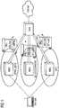
Figure 1 illustrates a system in which a MN is attached to multiple access networks at the same time via its interfaces. As shown inFigure 1 , an LMA may need to differentiate the fact that the PBUs are from the same MN but from different access networks. The LMA may accomplish this objective by looking at the Access Technology (AT) field or the Interface ID (IID) field in the PBU message. - Such an example scenario is further illustrated by
Figure 2 , as discussed below. - As shown in
Figure 2 , at step (1), an MN, which has interfaces I1, I2 and 13, attaches via Interface I1 to an LTE network. Next, atstep 2, MAG1 in the LTE network sends a PBU to the assigned LMA on behalf of the MN. The MN-ID field in the PBU, in this example, is set to: MN@operatorX.com (for example). The Access Network Type field in the PBU in this example is set to = LTE (because, in this example, an LTE access network is the network of MAGI, to which the MN has attached). The MAG1 inserts an Interface ID if it is aware of the MNs Interface ID (IID), and otherwise it leaves the MN-Interface-ID field empty (or set to 0). Next, at step (3), when the LMA has received the PBU from MAGI, the LMA assigns a prefix, P1, to the MN and sends the prefix via PBAck to MAG1. - Subsequently, at step (4), the MN attaches via a WiFi interface, 12, to an 802.11g network that has PMIP6 capability. Then, at step (5), MAG2 in the 802.11g network that the MN is attached to sends a PBU to the LMA on behalf of the MN. The MN-ID field in the PBU is, in this example, set to: MN@operatorX.com (example). The Access Network Type field in the PBU in this example is set to: 802.11g. MAG2 inserts an Interface ID if it is aware of the MNs IID, and otherwise it leaves the MN-Interface-ID field empty (or set to 0).
- Next, at step (6), the LMA that receives the PBU from MAG2 processes it and notes that the MN-ID field is the same for which it already has assigned a prefix, and that the MN-ID field exists in the binding cache. However the LMA can recognize that the access network type from which the PBU was sent is different by parsing the Access Network type field. It can also realize that the Interface by which the MN is attaching to the network is different if the Interface ID field was available in both PBUs received from MAG1 and MAG2. The LMA can then choose a different prefix, P2, and assign it to the MN, sending prefix P2 to MAG2 in the PBAck.
- The prefix in step (6) can be Prefix P1 if the LMA is aware that the MN is capable of handling the same prefix or if the LMA is aware of the MN having a virtual interface for the interfaces that are being used by the MN to connect to the two networks. The LMA can also have a policy that would allow the LMA to recognize the capability of an MN attaching to the LMA via MAG2 and assign Prefix P1 itself in the PBAck.
- Finally, at step (7), the MN can receive prefix P2 via a router advertisement from MAG2 on
Interface 12. The MN can create an address from Prefix P2 (using stateless address autoconfiguration) and can associate that address tointerface 12. - In the above described scenario, the LMA can be aware of which prefix to assign to an MN because of the awareness that the PBU for the MN (with a common ID) is coming from a different interface/access network. Accordingly, the solution may be relatively uncomplicated to implement, as it may be implemented, for example, by extending the PBU with two new parameters, and employing appropriate processing in the MN, MAGs, and LMA. Certain advantages of the described embodiments include that they can help to solve the issues associated with MNs that have multiple interfaces and can attach simultaneously via these interfaces.
- If an MN with a common Identifier (NAI) attaches to MAGs in different access networks via different interfaces, the LMA needs to be able to differentiate the fact that the PBUs are from the same MN but from different interfaces.
- More specifically, the LMA, on seeing the PBU with the same NAI but with a different access technology indication or interface identifier could assign a unique prefix via the PBAck, where the unique prefix does not conflict with the prefix assigned to another interface. This solution would enable an MN to attach to different MAGs that are in different access networks of differing technologies and not cause conflicts in prefix assignment or confuse the LMA into thinking that the MN had performed a handover (HO).
- This solution may be useful, for example, for interworking between LTE and High Rate Packet Data (HRPD)/Evolution Data Optimized (EV-DO) or between WiMAX and HRPD, or in other similar situations. Thus, an MN can be connected to multiple networks at the same time and hence the ability to differentiate the access technology to which it is attached may be valuable.
-
Figure 3 illustrates a system according to an embodiment of the present invention. The system, as shown inFigure 3 , can include a mobile node (MN) 310, a plurality of mobility access gateways (MAGs) 320, 330, and 340 (additional MAGs may be included, but are not illustrated, for simplicity), and a local mobility anchor or agent (LMA) 350. - The
LMA 350 can include a receivingunit 352 configured to receive data from external devices, aprocessing unit 354 configured to process received data and prepare data to be sent, and a sendingunit 356 configured to send data to external devices. Each of theunits LMA 350 can also include amemory 358 for storing data. Thememory 358 can be either internal or external toLMA 350. Examples of memories include hard drives, flash Random Access Memory (RAM), and Compact Disc Read Only Memory (CD-ROM). - A
first MAG 320 can be configured to function as an interface. TheMAG 320 can include a preparingunit 324 configured to prepare an access individuated indicator, such as an access technology indication or an interface identifier. TheMAG 320 can include a sendingunit 326 configured to send data to external devices and a receivingunit 322 configured to receive data from external devices. Each of theunits MAG 320 can include amemory 328 for storing data. Examples of memories include hard drives, flash Random Access Memory (RAM), and Compact Disc Read Only Memory (CD-ROM). - The details of
MAGS MAG 320. There is no need, however, forMAGS MAG 320, and consequently MAGS 330 and 340 can vary considerably fromMAG 320, each ofMAGS - The
MN 310 can including an attachingunit 316 configured to attach to a plurality of interfaces, and to send data to external devices. TheMN 310 can also include aprocessing unit 314 configured to prepare attachment and data to be sent, as well as data received or stored in memory. TheMN 310 can further include a receivingunit 312 configured to receive data from external devices. Each of theunits MN 310 can include amemory 318 for storing data. Examples of memories include hard drives, flash Random Access Memory (RAM), and Compact Disc Read Only Memory (CD-ROM). - The
MN 310 can communicate with one or more of theMAGs communication link 360, which may, for example, be a wireless communication link. Each of theMAGs communication link 360, but also asecond communication link 370, which may, for example, be a wired communication link, such as a coaxial cable connection or a fiber optic connection. -
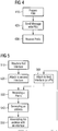
Figure 4 illustrates a method according to an embodiment of the present invention. As shown inFigure 4 , a method can include preparing 410 an access individuated indicator, wherein the access individuated indicator can include an access technology indication or an interface identifier. The access individuated indicator can assist the LMA in identifying an individual access technology from among a plurality of possible access technologies or a particular access interface from among a plurality of access interfaces. - The method can also include sending 420 a binding message to a local mobility entity including the access individuated indicator. The interface identifier can be obtained from a mobile node during attachment or from an access, authorization, and accounting function during authentication. The binding message can be sent from a mobility access gateway. The local mobility entity can be a local mobility anchor or agent.
- The method shown in
Figure 4 can optionally further include receiving 430 a prefix for a mobile node, wherein the prefix was generated in response to the binding message. -
Figure 5 illustrates another method according to an embodiment of the present invention. As shown inFigure 5 , the method can include attaching 510 to a first interface and attaching 520 to a second interface in parallel. The method can further include receiving 530 a prefix corresponding to at least one of the first or second interfaces, generating 540 a corresponding new address for a mobile node based on the prefix, and associating 550 the new address with the corresponding interface. - The method can further include attaching 560 to a third interface, and then receiving a second prefix corresponding to the third interface (as in 530 above), generating a second new address for a mobile node based on the second prefix (as in 540 above), and associating the second new address with the third interface (as in 550). This method can be repeated an indefinite number of times.
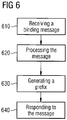
-
Figure 6 illustrates a further method according to an embodiment of the present invention. As shown inFigure 6 , the method can include receiving 610 a binding message including an access individuated indicator. The method can also include processing 620 the message to permit a parallel connection, wherein the parallel connection is parallel to an existing connection. - The method can further including generating 630 a prefix corresponding to an interface associated with the access individuated indicator. The method can additionally include responding 640 to the message with a binding acknowledgement message that includes the prefix.
- One having ordinary skill in the art will readily understand that the invention as discussed above may be practiced with steps in a different order, and/or with hardware elements in configurations which are different than those which are disclosed. Therefore, although the invention has been described based upon these preferred embodiments, it would be apparent to those of skill in the art that certain modifications, variations, and alternative constructions would be apparent, while remaining within the scope of the invention, which is defined by the attached claims.
Claims (11)
- A method comprising:preparing (410), by a mobility access gateway (320, 330, 340), an access technology indicator that indicates an access technology type by which a mobile node attaches to the mobility access gateway;sending (420), by the mobility access gateway (320, 330, 340), a binding message to a local mobility entity (350) including the access technology indicator; andreceiving (430), by the mobility access gateway (320, 330, 340) from the local mobility entity (350), a prefix corresponding to a first interface through which the mobile node (310) is attached to the mobility access gateway, wherein the prefix was generated in response to the binding message.
- A method as claimed in claim 1, further comprising:
sending the prefix to the mobile node. - A method as claimed in any preceding claim, comprising:attaching (510), by the mobile node, to the first interface;receiving, by the mobile node from the mobility access gateway (320, 330, 340) the prefix;generating (540), by the mobile node, a corresponding new address for the mobile node (310) based on the prefix;associating (550), by the mobile node, the new address with the first interface.
- A method as claimed in claim 3, comprising:
attaching (510), by the mobile node, to a second interface in parallel with the first interface, wherein the first and second interfaces correspond to different access technologies. - A method comprising:receiving (610), by a local mobility entity, from a mobility access gateway a binding message including an access technology indicator that indicates an access technology type by which a mobile node attaches to the mobility access gateway;processing (620), by the local mobility entity, the message to permit a parallel connection, wherein the parallel connection is parallel to an existing connection;generating (630), by the local mobility entity, a prefix corresponding to a first interface associated with the access technology indicator; andresponding (640), by the local mobility entity, to the message with a binding acknowledgement message that includes the prefix.
- An apparatus (320, 330, 340) of a mobility access gateway, comprising:a preparing unit configured to prepare (410) an access technology indicator that indicates an access technology type by which a mobile node attaches to the mobility access gateway;a sending unit configured to send (420) a binding message to a local mobility entity (350) including the access technology indicator; anda receiving unit configured to receive (430) from the local mobility entity (350) a prefix corresponding to a first interface through which the mobile node (310) is attached to the apparatus, wherein the prefix was generated in response to the binding message.
- An apparatus as claimed in claim 6, further comprising:
a sending unit configured to send the prefix to the mobile node. - An apparatus (350) of a local mobility entity, comprising:a receiving unit configured to receive (610) from a mobility access gateway a binding message including an access technology indicator that indicates an access technology type by which a mobile node attaches to the mobility access gateway;a processing unit configured to process (620) the message to permit a parallel connection, wherein the parallel connection is parallel to an existing connection, wherein the processing unit is configured to generate (630) a prefix corresponding to a first interface associated with the access technology indicator; anda sending unit configured to respond (640) to the message with a binding acknowledgement message that includes the prefix.
- A system, comprising:a first apparatus as claimed in any of claims 6 to 7, wherein the first apparatus further comprises a sending unit configured to send the prefix; anda second apparatus of a mobile node comprising:an attaching unit configured to attach (510) to the first interface;a receiving unit configured to receive (530) the prefix from the first apparatus, wherein the prefix corresponds to the first interface; anda processing unit configured to generate (540) a corresponding new address for the mobile node (310) based on the prefix and to associate (550) the new address with the first interface.
- The system of claim 9, further comprising:
a third apparatus as claimed in claim 8. - A computer program product comprising code means adapted to produce the steps of any one of claims 1-2 or claim 5 when loaded into the memory of a computer.
Applications Claiming Priority (2)
| Application Number | Priority Date | Filing Date | Title |
|---|---|---|---|
| US96058807P | 2007-10-04 | 2007-10-04 | |
| PCT/EP2008/063071 WO2009043846A1 (en) | 2007-10-04 | 2008-09-30 | Access technology indication for proxy mobile internet protocol version 6 |
Publications (2)
| Publication Number | Publication Date |
|---|---|
| EP2201739A1 EP2201739A1 (en) | 2010-06-30 |
| EP2201739B1 true EP2201739B1 (en) | 2019-11-20 |
Family
ID=40418867
Family Applications (1)
| Application Number | Title | Priority Date | Filing Date |
|---|---|---|---|
| EP08804911.9A Active EP2201739B1 (en) | 2007-10-04 | 2008-09-30 | Access technology indication for proxy mobile internet protocol |
Country Status (4)
| Country | Link |
|---|---|
| US (1) | US8121047B2 (en) |
| EP (1) | EP2201739B1 (en) |
| ES (1) | ES2767273T3 (en) |
| WO (1) | WO2009043846A1 (en) |
Families Citing this family (14)
| Publication number | Priority date | Publication date | Assignee | Title |
|---|---|---|---|---|
| EP2206401B1 (en) | 2007-10-10 | 2017-05-31 | BlackBerry Limited | Support for multi-homing protocols |
| WO2009067227A1 (en) | 2007-11-21 | 2009-05-28 | Nortel Networks Limited | Support for continuity of tunnel communications for mobile nodes having multiple care of addressing |
| US8385290B2 (en) * | 2007-11-30 | 2013-02-26 | Telefonaktiebolaget Lm Ericsson (Publ) | Method and apparatus for handling a local breakout session |
| WO2009101780A1 (en) * | 2008-02-12 | 2009-08-20 | Panasonic Corporation | Position information management device, network edge device, and mobile terminal |
| EP2272000A4 (en) * | 2008-03-19 | 2012-12-26 | Research In Motion Ltd | SUPPORT FOR MULTIPLE ACCOMMODATION PROTOCOLS USING TRANSIENT RECORDING AND EXTENSIBLE BINDING REVOCATION MESSAGES |
| CN101605319B (en) * | 2008-06-12 | 2013-04-17 | 华为技术有限公司 | State-switching information-processing method, movable access gateway and movable terminal |
| WO2010041440A1 (en) * | 2008-10-08 | 2010-04-15 | パナソニック株式会社 | Interface switching system, mobile node, proxy node, and mobile management node |
| WO2010045302A1 (en) * | 2008-10-14 | 2010-04-22 | Starent Networks, Corp | Flow balancing in communications networks |
| US8908662B2 (en) * | 2009-02-11 | 2014-12-09 | Futurewei Technologies, Inc. | Apparatus and method of flow movement for network-based mobility management protocol |
| WO2010124720A1 (en) * | 2009-04-27 | 2010-11-04 | Telefonaktiebolaget Lm Ericsson (Publ) | Method and apparatus for access selection in mobile ip networks |
| CN101873572B (en) * | 2009-04-27 | 2012-08-29 | 中国移动通信集团公司 | Data transmission method, system and relevant network equipment based on PMIPv6 |
| CN104137583A (en) * | 2012-03-01 | 2014-11-05 | 交互数字专利控股公司 | Method and apparatus for supporting dynamic and distributed mobility management |
| CN104219726B (en) * | 2013-06-04 | 2018-12-14 | 中兴通讯股份有限公司 | A kind of routing optimization method and device |
| CN104378784A (en) * | 2014-11-05 | 2015-02-25 | 工业和信息化部电子第五研究所 | Data forwarding method and system |
Family Cites Families (11)
| Publication number | Priority date | Publication date | Assignee | Title |
|---|---|---|---|---|
| KR100754383B1 (en) * | 2001-07-27 | 2007-08-31 | 삼성전자주식회사 | Method and apparatus for forming local area and local movement control device |
| US20040141477A1 (en) * | 2003-01-22 | 2004-07-22 | Institute For Infocomm Research | Method, system and mobile host for mobility pattern based selection of a local mobility agent |
| US7228133B2 (en) * | 2003-12-19 | 2007-06-05 | Nortel Networks Limited | Mobile IP node device and access information |
| JP4423118B2 (en) * | 2004-06-08 | 2010-03-03 | 株式会社エヌ・ティ・ティ・ドコモ | Mobile communication system, access router, management apparatus, and mobile communication method |
| FR2879883B1 (en) * | 2004-12-17 | 2007-04-27 | Cit Alcatel | METHOD FOR IMPROVING MOBILITY MANAGEMENT IN A CELLULAR MOBILE COMMUNICATIONS SYSTEM |
| US20060291422A1 (en) * | 2005-06-27 | 2006-12-28 | Nokia Corporation | Mobility management in a communication system of at least two communication networks |
| DE602006016806D1 (en) * | 2005-07-28 | 2010-10-21 | France Telecom | METHOD FOR GIVING A TEMPORARY ADDRESS TO A MOBILE NODE OF A TELECOMMUNICATIONS SYSTEM, DEVICES AND PROGRAMS FOR ITS IMPLEMENTATION |
| KR101221610B1 (en) * | 2005-11-03 | 2013-01-14 | 삼성전자주식회사 | Apparatus and Method for Supporting Fast Mobility IP with Link Identifier Prefix in Wireless Communication System |
| US8625609B2 (en) * | 2006-05-19 | 2014-01-07 | Futurewei Technologies Inc. | Using DHCPv6 and AAA for mobile station prefix delegation and enhanced neighbor discovery |
| US7949876B2 (en) * | 2006-12-28 | 2011-05-24 | Telefonaktiebolaget L M Ericsson (Publ) | Method and nodes for optimized and secure communication between routers and hosts |
| US9516495B2 (en) * | 2007-03-01 | 2016-12-06 | Futurewei Technologies, Inc. | Apparatus and methods of PMIPv6 route optimization protocol |
-
2008
- 2008-09-30 EP EP08804911.9A patent/EP2201739B1/en active Active
- 2008-09-30 WO PCT/EP2008/063071 patent/WO2009043846A1/en not_active Ceased
- 2008-09-30 ES ES08804911T patent/ES2767273T3/en active Active
- 2008-10-03 US US12/285,407 patent/US8121047B2/en active Active
Non-Patent Citations (1)
| Title |
|---|
| None * |
Also Published As
| Publication number | Publication date |
|---|---|
| US8121047B2 (en) | 2012-02-21 |
| WO2009043846A1 (en) | 2009-04-09 |
| ES2767273T3 (en) | 2020-06-17 |
| US20090094693A1 (en) | 2009-04-09 |
| EP2201739A1 (en) | 2010-06-30 |
Similar Documents
| Publication | Publication Date | Title |
|---|---|---|
| EP2201739B1 (en) | Access technology indication for proxy mobile internet protocol | |
| US8391226B2 (en) | Method and apparatus for use in a communications network | |
| EP2304981B1 (en) | Anchoring services of a mobile station attached to a first service domain at a home agent in a second service domain | |
| US8780800B2 (en) | Optimized home link detection | |
| EP2272262B1 (en) | Circuit switched domain codec list for single radio voice call continuity | |
| US20080254768A1 (en) | Packet data network connectivity domain selection and bearer setup | |
| EP1974524B1 (en) | Telecommunications system and method | |
| US8565159B2 (en) | Telecommunications system and method | |
| WO2008030063A1 (en) | Method and system for handoff of mobile node in mobile communication system supporting proxy mobile internet protocol | |
| WO2009111960A1 (en) | Local mobility anchor registration method, system and device | |
| US8824352B2 (en) | Mobile access gateway, mobile node and method for processing handover state information | |
| US20120051323A1 (en) | Method and communication entity for proving a communication connection | |
| JPWO2010073620A1 (en) | Handover method, mobile terminal and home agent used in the method | |
| US8761119B2 (en) | Handover method, and mobile terminal and home agent used in the method | |
| US20100208663A1 (en) | Communication system, mobile terminal, and network node | |
| EP2457409A1 (en) | Method and device for conveying traffic in a proxy mobile ip system | |
| CN103999543B (en) | PMIP Protocol Enhancements | |
| Corici et al. | Proactive Vertical Handover Optimizations in the 3GPP Evolved Packet Core | |
| HK1219367B (en) | System and method for supporting the transfer of internet data packets when a mobile node roams from a home network to a visited network | |
| KR20120058427A (en) | Method and apparatus for configuring subscriber quality of service profiles |
Legal Events
| Date | Code | Title | Description |
|---|---|---|---|
| PUAI | Public reference made under article 153(3) epc to a published international application that has entered the european phase |
Free format text: ORIGINAL CODE: 0009012 |
|
| 17P | Request for examination filed |
Effective date: 20100504 |
|
| AK | Designated contracting states |
Kind code of ref document: A1 Designated state(s): AT BE BG CH CY CZ DE DK EE ES FI FR GB GR HR HU IE IS IT LI LT LU LV MC MT NL NO PL PT RO SE SI SK TR |
|
| AX | Request for extension of the european patent |
Extension state: AL BA MK RS |
|
| DAX | Request for extension of the european patent (deleted) | ||
| RAP1 | Party data changed (applicant data changed or rights of an application transferred) |
Owner name: NOKIA SOLUTIONS AND NETWORKS OY |
|
| 17Q | First examination report despatched |
Effective date: 20160502 |
|
| STAA | Information on the status of an ep patent application or granted ep patent |
Free format text: STATUS: EXAMINATION IS IN PROGRESS |
|
| GRAP | Despatch of communication of intention to grant a patent |
Free format text: ORIGINAL CODE: EPIDOSNIGR1 |
|
| STAA | Information on the status of an ep patent application or granted ep patent |
Free format text: STATUS: GRANT OF PATENT IS INTENDED |
|
| INTG | Intention to grant announced |
Effective date: 20190531 |
|
| RAP1 | Party data changed (applicant data changed or rights of an application transferred) |
Owner name: NOKIA SOLUTIONS AND NETWORKS OY |
|
| GRAJ | Information related to disapproval of communication of intention to grant by the applicant or resumption of examination proceedings by the epo deleted |
Free format text: ORIGINAL CODE: EPIDOSDIGR1 |
|
| STAA | Information on the status of an ep patent application or granted ep patent |
Free format text: STATUS: EXAMINATION IS IN PROGRESS |
|
| GRAR | Information related to intention to grant a patent recorded |
Free format text: ORIGINAL CODE: EPIDOSNIGR71 |
|
| GRAS | Grant fee paid |
Free format text: ORIGINAL CODE: EPIDOSNIGR3 |
|
| STAA | Information on the status of an ep patent application or granted ep patent |
Free format text: STATUS: GRANT OF PATENT IS INTENDED |
|
| GRAA | (expected) grant |
Free format text: ORIGINAL CODE: 0009210 |
|
| STAA | Information on the status of an ep patent application or granted ep patent |
Free format text: STATUS: THE PATENT HAS BEEN GRANTED |
|
| INTC | Intention to grant announced (deleted) | ||
| INTG | Intention to grant announced |
Effective date: 20191009 |
|
| AK | Designated contracting states |
Kind code of ref document: B1 Designated state(s): AT BE BG CH CY CZ DE DK EE ES FI FR GB GR HR HU IE IS IT LI LT LU LV MC MT NL NO PL PT RO SE SI SK TR |
|
| REG | Reference to a national code |
Ref country code: GB Ref legal event code: FG4D |
|
| REG | Reference to a national code |
Ref country code: CH Ref legal event code: EP |
|
| REG | Reference to a national code |
Ref country code: DE Ref legal event code: R096 Ref document number: 602008061683 Country of ref document: DE |
|
| REG | Reference to a national code |
Ref country code: IE Ref legal event code: FG4D |
|
| REG | Reference to a national code |
Ref country code: AT Ref legal event code: REF Ref document number: 1205456 Country of ref document: AT Kind code of ref document: T Effective date: 20191215 |
|
| REG | Reference to a national code |
Ref country code: NL Ref legal event code: MP Effective date: 20191120 |
|
| REG | Reference to a national code |
Ref country code: LT Ref legal event code: MG4D |
|
| PG25 | Lapsed in a contracting state [announced via postgrant information from national office to epo] |
Ref country code: NL Free format text: LAPSE BECAUSE OF FAILURE TO SUBMIT A TRANSLATION OF THE DESCRIPTION OR TO PAY THE FEE WITHIN THE PRESCRIBED TIME-LIMIT Effective date: 20191120 Ref country code: LV Free format text: LAPSE BECAUSE OF FAILURE TO SUBMIT A TRANSLATION OF THE DESCRIPTION OR TO PAY THE FEE WITHIN THE PRESCRIBED TIME-LIMIT Effective date: 20191120 Ref country code: SE Free format text: LAPSE BECAUSE OF FAILURE TO SUBMIT A TRANSLATION OF THE DESCRIPTION OR TO PAY THE FEE WITHIN THE PRESCRIBED TIME-LIMIT Effective date: 20191120 Ref country code: NO Free format text: LAPSE BECAUSE OF FAILURE TO SUBMIT A TRANSLATION OF THE DESCRIPTION OR TO PAY THE FEE WITHIN THE PRESCRIBED TIME-LIMIT Effective date: 20200220 Ref country code: BG Free format text: LAPSE BECAUSE OF FAILURE TO SUBMIT A TRANSLATION OF THE DESCRIPTION OR TO PAY THE FEE WITHIN THE PRESCRIBED TIME-LIMIT Effective date: 20200220 Ref country code: FI Free format text: LAPSE BECAUSE OF FAILURE TO SUBMIT A TRANSLATION OF THE DESCRIPTION OR TO PAY THE FEE WITHIN THE PRESCRIBED TIME-LIMIT Effective date: 20191120 Ref country code: GR Free format text: LAPSE BECAUSE OF FAILURE TO SUBMIT A TRANSLATION OF THE DESCRIPTION OR TO PAY THE FEE WITHIN THE PRESCRIBED TIME-LIMIT Effective date: 20200221 Ref country code: LT Free format text: LAPSE BECAUSE OF FAILURE TO SUBMIT A TRANSLATION OF THE DESCRIPTION OR TO PAY THE FEE WITHIN THE PRESCRIBED TIME-LIMIT Effective date: 20191120 |
|
| PG25 | Lapsed in a contracting state [announced via postgrant information from national office to epo] |
Ref country code: IS Free format text: LAPSE BECAUSE OF FAILURE TO SUBMIT A TRANSLATION OF THE DESCRIPTION OR TO PAY THE FEE WITHIN THE PRESCRIBED TIME-LIMIT Effective date: 20200320 Ref country code: HR Free format text: LAPSE BECAUSE OF FAILURE TO SUBMIT A TRANSLATION OF THE DESCRIPTION OR TO PAY THE FEE WITHIN THE PRESCRIBED TIME-LIMIT Effective date: 20191120 |
|
| REG | Reference to a national code |
Ref country code: ES Ref legal event code: FG2A Ref document number: 2767273 Country of ref document: ES Kind code of ref document: T3 Effective date: 20200617 |
|
| PG25 | Lapsed in a contracting state [announced via postgrant information from national office to epo] |
Ref country code: CZ Free format text: LAPSE BECAUSE OF FAILURE TO SUBMIT A TRANSLATION OF THE DESCRIPTION OR TO PAY THE FEE WITHIN THE PRESCRIBED TIME-LIMIT Effective date: 20191120 Ref country code: RO Free format text: LAPSE BECAUSE OF FAILURE TO SUBMIT A TRANSLATION OF THE DESCRIPTION OR TO PAY THE FEE WITHIN THE PRESCRIBED TIME-LIMIT Effective date: 20191120 Ref country code: PT Free format text: LAPSE BECAUSE OF FAILURE TO SUBMIT A TRANSLATION OF THE DESCRIPTION OR TO PAY THE FEE WITHIN THE PRESCRIBED TIME-LIMIT Effective date: 20200412 Ref country code: EE Free format text: LAPSE BECAUSE OF FAILURE TO SUBMIT A TRANSLATION OF THE DESCRIPTION OR TO PAY THE FEE WITHIN THE PRESCRIBED TIME-LIMIT Effective date: 20191120 Ref country code: DK Free format text: LAPSE BECAUSE OF FAILURE TO SUBMIT A TRANSLATION OF THE DESCRIPTION OR TO PAY THE FEE WITHIN THE PRESCRIBED TIME-LIMIT Effective date: 20191120 |
|
| REG | Reference to a national code |
Ref country code: DE Ref legal event code: R097 Ref document number: 602008061683 Country of ref document: DE |
|
| PG25 | Lapsed in a contracting state [announced via postgrant information from national office to epo] |
Ref country code: SK Free format text: LAPSE BECAUSE OF FAILURE TO SUBMIT A TRANSLATION OF THE DESCRIPTION OR TO PAY THE FEE WITHIN THE PRESCRIBED TIME-LIMIT Effective date: 20191120 |
|
| REG | Reference to a national code |
Ref country code: AT Ref legal event code: UEP Ref document number: 1205456 Country of ref document: AT Kind code of ref document: T Effective date: 20191120 |
|
| PLBE | No opposition filed within time limit |
Free format text: ORIGINAL CODE: 0009261 |
|
| STAA | Information on the status of an ep patent application or granted ep patent |
Free format text: STATUS: NO OPPOSITION FILED WITHIN TIME LIMIT |
|
| 26N | No opposition filed |
Effective date: 20200821 |
|
| PG25 | Lapsed in a contracting state [announced via postgrant information from national office to epo] |
Ref country code: PL Free format text: LAPSE BECAUSE OF FAILURE TO SUBMIT A TRANSLATION OF THE DESCRIPTION OR TO PAY THE FEE WITHIN THE PRESCRIBED TIME-LIMIT Effective date: 20191120 Ref country code: SI Free format text: LAPSE BECAUSE OF FAILURE TO SUBMIT A TRANSLATION OF THE DESCRIPTION OR TO PAY THE FEE WITHIN THE PRESCRIBED TIME-LIMIT Effective date: 20191120 |
|
| REG | Reference to a national code |
Ref country code: DE Ref legal event code: R119 Ref document number: 602008061683 Country of ref document: DE |
|
| PG25 | Lapsed in a contracting state [announced via postgrant information from national office to epo] |
Ref country code: MC Free format text: LAPSE BECAUSE OF FAILURE TO SUBMIT A TRANSLATION OF THE DESCRIPTION OR TO PAY THE FEE WITHIN THE PRESCRIBED TIME-LIMIT Effective date: 20191120 |
|
| REG | Reference to a national code |
Ref country code: CH Ref legal event code: PL |
|
| GBPC | Gb: european patent ceased through non-payment of renewal fee |
Effective date: 20200930 |
|
| REG | Reference to a national code |
Ref country code: BE Ref legal event code: MM Effective date: 20200930 |
|
| PG25 | Lapsed in a contracting state [announced via postgrant information from national office to epo] |
Ref country code: LU Free format text: LAPSE BECAUSE OF NON-PAYMENT OF DUE FEES Effective date: 20200930 |
|
| PG25 | Lapsed in a contracting state [announced via postgrant information from national office to epo] |
Ref country code: DE Free format text: LAPSE BECAUSE OF NON-PAYMENT OF DUE FEES Effective date: 20210401 |
|
| PG25 | Lapsed in a contracting state [announced via postgrant information from national office to epo] |
Ref country code: GB Free format text: LAPSE BECAUSE OF NON-PAYMENT OF DUE FEES Effective date: 20200930 Ref country code: LI Free format text: LAPSE BECAUSE OF NON-PAYMENT OF DUE FEES Effective date: 20200930 Ref country code: IE Free format text: LAPSE BECAUSE OF NON-PAYMENT OF DUE FEES Effective date: 20200930 Ref country code: CH Free format text: LAPSE BECAUSE OF NON-PAYMENT OF DUE FEES Effective date: 20200930 Ref country code: BE Free format text: LAPSE BECAUSE OF NON-PAYMENT OF DUE FEES Effective date: 20200930 |
|
| PG25 | Lapsed in a contracting state [announced via postgrant information from national office to epo] |
Ref country code: TR Free format text: LAPSE BECAUSE OF FAILURE TO SUBMIT A TRANSLATION OF THE DESCRIPTION OR TO PAY THE FEE WITHIN THE PRESCRIBED TIME-LIMIT Effective date: 20191120 Ref country code: MT Free format text: LAPSE BECAUSE OF FAILURE TO SUBMIT A TRANSLATION OF THE DESCRIPTION OR TO PAY THE FEE WITHIN THE PRESCRIBED TIME-LIMIT Effective date: 20191120 Ref country code: CY Free format text: LAPSE BECAUSE OF FAILURE TO SUBMIT A TRANSLATION OF THE DESCRIPTION OR TO PAY THE FEE WITHIN THE PRESCRIBED TIME-LIMIT Effective date: 20191120 |
|
| P01 | Opt-out of the competence of the unified patent court (upc) registered |
Effective date: 20230527 |
|
| PGFP | Annual fee paid to national office [announced via postgrant information from national office to epo] |
Ref country code: IT Payment date: 20250825 Year of fee payment: 18 |
|
| PGFP | Annual fee paid to national office [announced via postgrant information from national office to epo] |
Ref country code: FR Payment date: 20250808 Year of fee payment: 18 Ref country code: AT Payment date: 20250827 Year of fee payment: 18 |
|
| PGFP | Annual fee paid to national office [announced via postgrant information from national office to epo] |
Ref country code: ES Payment date: 20251015 Year of fee payment: 18 |