EP2201855B1 - Schliessvorrichtung, insbesondere für Sportschuhe - Google Patents
Schliessvorrichtung, insbesondere für Sportschuhe Download PDFInfo
- Publication number
- EP2201855B1 EP2201855B1 EP09180469.0A EP09180469A EP2201855B1 EP 2201855 B1 EP2201855 B1 EP 2201855B1 EP 09180469 A EP09180469 A EP 09180469A EP 2201855 B1 EP2201855 B1 EP 2201855B1
- Authority
- EP
- European Patent Office
- Prior art keywords
- extension
- lever arm
- pair
- base
- arms
- Prior art date
- Legal status (The legal status is an assumption and is not a legal conclusion. Google has not performed a legal analysis and makes no representation as to the accuracy of the status listed.)
- Active
Links
Images



Classifications
-
- A—HUMAN NECESSITIES
- A43—FOOTWEAR
- A43C—FASTENINGS OR ATTACHMENTS OF FOOTWEAR; LACES IN GENERAL
- A43C11/00—Other fastenings specially adapted for shoes
- A43C11/14—Clamp fastenings, e.g. strap fastenings; Clamp-buckle fastenings; Fastenings with toggle levers
- A43C11/1406—Fastenings with toggle levers; Equipment therefor
- A43C11/142—Fastenings with toggle levers with adjustment means provided for on the shoe, e.g. rack
- A43C11/1433—Fastenings with toggle levers with adjustment means provided for on the shoe, e.g. rack characterised by means to decrease required force for the closure movement of the toggle lever
-
- A—HUMAN NECESSITIES
- A43—FOOTWEAR
- A43B—CHARACTERISTIC FEATURES OF FOOTWEAR; PARTS OF FOOTWEAR
- A43B13/00—Soles; Sole-and-heel integral units
- A43B13/14—Soles; Sole-and-heel integral units characterised by the constructive form
- A43B13/141—Soles; Sole-and-heel integral units characterised by the constructive form with a part of the sole being flexible, e.g. permitting articulation or torsion
Definitions
- the present invention relates to a closure device particularly for sports shoes.
- closure devices which comprise levers adapted to allow the fastening of a first flap and a second flap, which constitute the shoe.
- Levers which comprise a lever arm, which can be gripped by the user and is associated with a first flap to be joined, which is connected, by means of an interconnection element, to a ring or hook which interacts for example with the teeth of a rack or a strap or band with teeth, which can be associated with the second flap to be joined of the shoe.
- Italian patent No. 0000232825 discloses a buckle for a shoe, particularly for ski boots, which comprises a base designed to be fixed on a boot part, a tensioning lever with two arms, which is articulated on this base by means of the ends of its arms, a first engagement element, which is designed to be fastened to a second engagement element which is fixed to another part of the shoe, and means for joining the first engagement element and the tensioning lever, such buckle being constituted by two telescopic parts.
- one of the two telescopic parts has adapted holes which provide two distinct mutual arrangement positions.
- Italian patent No. 1298824 is also known which is constituted by a lever, particularly for sports shoes, which comprises a lever arm which is rotatably associated, at a first end, with a support which is coupled to a flap of the shoe, an auxiliary grip lever for the user being associated or associable with the lever arm and being adapted to increase temporarily the useful length of the lever arm.
- the auxiliary lever if it is not distinct and therefore not associated with the lever arm, must be stored necessarily by the user, for example in a pocket, during sports practice, with the consequent possibility of losing it; in any case, interconnection with the lever arm is not easy, since sports activity usually occurs while wearing gloves and the seat for insertion in the lever arm is usually filled with snow or ice.
- auxiliary lever is articulated to one end of the lever arm, a drawback is observed due to the fact that in order to perform closure, the user must lift the auxiliary lever, gripping it in a vise-like manner between the thumb and index finger until he can insert the palm of his hand under the auxiliary lever and then turn it in the closing direction.
- the aim of the present invention is to solve the above mentioned technical problems, eliminating the drawbacks of the cited background art, by providing a closure device that allows to achieve both opening and closure of a lever rapidly and easily and with an effort containment that can be applied in both cases.
- an object of the invention is to provide a closure device for sports shoes that can be activated easily even in the presence of snow on the lever arm.
- Another object is to obtain a closure device for sports shoes that does not modify the vertical dimensions of the lever arm.
- Another object is to obtain a closure device for sports shoes in which its activation and deactivation are easy for the user even if he is wearing gloves and even in low-temperature conditions.
- Another object is to obtain a device which combines the above cited characteristics with those of being structurally simple and of having low production costs.
- a closure device particularly for sports shoes, which comprises a lever arm, which is coupled to a first flap of said shoe and articulated to an interconnection element for a means for engagement with a second flap of said shoe, characterized in that an extension is slidingly associated with said lever arm, in contrast with elastically compressible means, and interacts selectively, in the fully extracted condition, with a temporary stop means.
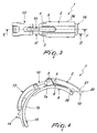
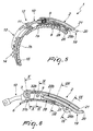
- the reference numeral 1 designates a closure device, particularly for sports shoes, which comprises a lever arm 2, which is associated rotatably, by means of a pair of first pivots 3 and 4, with a pair of first shoulders 5a, 5b, which protrude from a base 6 which is coupled to a first flap 7a of the shoe by means of a first rivet or screw 8.
- the lever arm 2 is articulated, by means of a second pivot 9, to an end of an interconnection element 10, which at the other end is rotatably associated, for example by means of a pivot 11, with a first end 12 of a hook 13, which interacts selectively with the teeth of a rack 14 which can be associated, by means of a second rivet or screw 15, with a second flap 7b of the shoe.
- the lever arm 2 has, in a lower region, a first central longitudinal seat 16, which is interposed between a pair of second longitudinal seats 17a, 17b, which accordingly are provided at the sides of the lever arm 2.
- the arms 18a, 18b of an extension 19 are associated slidingly within the pair of second longitudinal seats 17a, 17b, and the extension 19 is U-shaped so as to form a first base 20, which is slightly inclined away from the first flap 7a and protrudes beyond the front perimetric edge 21 of the lever arm 2.
- the extension 19 is preferably made of steel wire and interacts with elastically compressible means constituted by a pair of first springs 22a, 22b which are arranged coaxially to the arms 18a, 18b.
- the pair of first springs 22a, 22b abuts at it ends at adapted protrusions 23a, 23b, which protrude proximate to one end of the pair of arms 18a, 18b and a wall 24 of a pair of tabs 25a, 25b which protrude downward along the sides of the lever arm 2 proximate to the front perimetric edge 21.
- the protrusions 23a, 23b are also designed to trap the extension 19 with respect to the lever arm 2 and at the same time leave the extension 19 free to move in the two directions which are longitudinal with respect to the lever arm 2.
- Each one of the pair of tabs 25a, 25b is provided with holes to allow the arrangement of a third pivot 26, which is arranged transversely to the lever arm 2 in a region that lies below the pair of arms 18a, 18b.
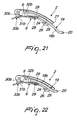
- a second substantially V-shaped spring 27 is arranged coaxially to the third pivot 26 and has an end which interacts with the lower surface of the lever arm 2 in the region of the first longitudinal seat 16 and the other end which interacts with a temporary stop means for the extension 19.
- Such means is constituted by a pawl 28, which is U-shaped in plan view so as to form a second base 29, which is flat and tapers slightly at the tip in the direction of the base 6, and from which two wings 30a, 30b protrude which have a tip 31a, 31b shaped like a slider, which is slightly arc-like with the concavity directed toward the base 6.
- Two second shoulders 32a, 32b protrude at right angles laterally and externally to the pair of wings 30a, 30b and are conveniently provided with holes for rotary interconnection with the second pivot 9.
- the slider-shaped tips 31a, 31b lie in a region located above adapted openings 33a, 33b formed on the underlying base 6.
- the operation of the closure device of the invention therefore entails that the user extracts the extension 19 by simply placing a finger at the first base 20, which is slightly inclined away from the first flap 7a; once the extension 19 has been extracted, even if it is drawn back continuously by the compression of the pair of first springs 22a, 22b, it remains firmly extended, since its retraction is contrasted by the pawl 28, the second base 29 of which is drawn counterclockwise by the second spring 27 toward the inside of the lever arm 2, arranging itself against the end of the arms 18a, 18b.
- the extension 19 can be retracted manually by compressing the tips 31a, 31b of the pawl 28 on the opposite side with respect to the base 6.
- the extension 19 is retracted automatically whenever the lever is closed, in view of the interaction of the tips 31a, 31b with the base 6.
- the invention has achieved the intended aim and objects, a device having been devised which allows to obtain both the opening and the closure of a lever rapidly and easily and with a containment of the effort that can be applied in both cases, the device being activatable even in the presence of snow on the lever arm.
- the lever arm can thus be extended functionally by extraction of the extension at will on the part of the user both during closure and during the opening of the lever, reducing the effort both during opening and during closure.
- extension Once the extension has been extracted, it is retained firmly externally with respect to the lever arm by the pawl, which hinders its retraction, while once it is extracted the extension requires no further maneuvers and is therefore immediately ready to be gripped with the palm of the hand in order to facilitate closure of the lever or to be gripped with the index finger in order to facilitate the opening of the lever.
- the overall thickness of the lever is low, because the extension is arranged in a central space of the lever arm that is normally unused.
- the extension can be made for example of steel wire, it is possible to achieve a scarcely visible aesthetic impact.
Landscapes
- Footwear And Its Accessory, Manufacturing Method And Apparatuses (AREA)
Claims (10)
- Eine Schließvorrichtung (1), insbesondere für Sportschuhe, die einen Hebelarm (2) umfasst, der ausgebildet ist, um mit einer ersten Lasche (7a) eines Schuhs gekoppelt und gelenkig mit einem Verbindungselement (10) für ein Mittel für den Eingriff mit einer zweiten Lasche (7b) des Schuhs verbunden zu werden, dadurch gekennzeichnet, dass eine Verlängerung (19), im Kontrast zu elastisch komprimierbaren Mitteln, verschiebbar mit dem Hebelarm (2) verbunden ist und im vollständig herausgezogenen Zustand selektiv mit einem temporären Anschlagmittel zusammenwirkt.
- Die Vorrichtung gemäß Anspruch 1, dadurch gekennzeichnet, dass der Hebelarm (2) in einem unteren Bereich mit einem ersten zentralen Längssitz (16) versehen ist, der zwischen einem Paar zweiter Längssitze (17a, 17b) angeordnet ist, wobei Arme (18a, 7.bb) der Verlängerung (19) verschiebbar innerhalb des Paares zweiter Längssitze (17a, 17b) verbunden sind und die Verlängerung (19) U-förmig ist, um so eine erste Basis (20) zu bilden, die leicht von der ersten Lasche (7a) fort geneigt ist und über die vordere perimetrische Kante (21) des Hebelarms (2) hinausragt, wobei die Verlängerung (19) vorzugsweise aus Stahldraht besteht.
- Die Vorrichtung gemäß Ansprüchen 1 und 2, dadurch gekennzeichnet, dass die Verlängerung (19) mit elastisch komprimierbaren Mitteln zusammenwirkt, die in einem Paar erster Federn (22a, 22b) bestehen, welche koaxial zu den Armen (18a, 18b) angeordnet sind, wobei das Paar erster Federn (22a, 22b) an seinen Enden an entsprechende Vorsprünge (23a, 23b) anstößt, die nahe einem Ende des Paares von Armen (18a, 18b) und an einer Wand (24) eines Paares von Nasen (25a, 25b) herausragen, welche entlang den Seiten des Hebelarms (2) nahe der vorderen perimetrischen Kante (21) nach unten ragen, wobei die Vorsprünge (23a, 23b) die Verlängerung (19) mit Bezug auf den Hebelarm (2) einschließen und gleichzeitig die Verlängerung (19) frei lassen, sich in beide Längsrichtungen mit Bezug auf den Hebelarm (2) zu bewegen.
- Die Vorrichtung gemäß Anspruch 1 und 3, dadurch gekennzeichnet, dass jede des Paares von Nasen (25a, 25b) mit Löchern versehen ist, um so die Anordnung eines dritten Zapfens (26) zu ermöglichen, der transversal zu dem Hebelarm (2) in einem Bereich angeordnet ist, welcher unterhalb des Paares von Armen (18a, 18b) liegt, wobei eine zweite im Wesentlichen V-förmige Feder (27) koaxial zu dem dritten Zapfen (26) angeordnet ist und ein Ende hat, das mit der unteren Oberfläche des Hebelarms (2) im Bereich des ersten Längssitzes (16) zusammenwirkt, und ein anderes Ende, das mit einem Mittel zum vorübergehenden Anhalten der Verlängerung (19) zusammenwirkt.
- Die Vorrichtung gemäß Anspruch 1 und 4, dadurch gekennzeichnet, dass das temporäre Anschlagmittel für die Verlängerung (19) in einer Klinke (28) besteht, die in der Grundrissansicht U-förmig ist, um so eine zweite Basis (29) zu bilden, die flach ist und sich an der Spitze in Richtung der Basis (6) leicht verjüngt und von der zwei Flügel (30a, 30b) abstehen, die eine schieberförmige Spitze (31a, 31b) haben, und die leicht bogenförmig ist, wobei die Ausbuchtung zur Basis (6) hin gerichtet ist.
- Die Vorrichtung gemäß Anspruch 1 und 5, dadurch gekennzeichnet, dass zwei zweite Schultern (32a, 32b) in rechten Winkeln seitlich und außerhalb des Paares von Flügeln (30a, 30b) herausragen und praktischerweise mit Löchern zur Drehverbindung mit dem zweiten Zapfen (9) versehen sind, wobei die schieberförmigen Spitzen (31a, 31b) in einem Bereich angeordnet sind, der über geeigneten Öffnungen (33a, 33b) liegt, welche in der darunterliegenden Basis (6) angebracht sind.
- Die Vorrichtung gemäß einem oder mehreren der Ansprüche 4 bis 6, dadurch gekennzeichnet, dass, sobald die Verlängerung (19) aus dem Hebelarm (2) gezogen wurde, sie kontinuierlich durch die Kompression des Paares erster Federn (22a, 22b) zurückgezogen wird, aber ausgefahren bleibt, weil die Klinke (28) ihrem Zurückziehen entgegenwirkt, deren zweite Basis (29) von der zweiten Feder (27) zum Inneren des Hebelarms (2) hin zurückgezogen wird, so dass sie sich gegen den Uhrzeigersinn dreht und gegen das Ende der Arme (18a, 18b) anordnet.
- Die Vorrichtung gemäß Anspruch 1 und 7, dadurch gekennzeichnet, dass die Verlängerung (19) durch ein Zusammendrücken der Spitzen (31a, 31b) der Klinke (28) auf der der Basis (6) gegenüberliegenden Seite manuell zurückgezogen werden kann.
- Die Vorrichtung gemäß Anspruch 1 und 8, dadurch gekennzeichnet, dass die Verlängerung (19) immer dann automatisch zurückgezogen wird, wenn die Spitzen (31a, 31b) mit der Basis (6) zusammenwirken.
- Die Vorrichtung gemäß Anspruch 3, dadurch gekennzeichnet, dass während des Schritts zum öffnen des Hebelarms die Reibung, die vorhanden ist, aufgrund der vom Benutzer ausgeübten Kraft, zwischen der Verlängerung (19) und den zweiten Längssitzen (17a, 17b), die Verlängerung herausgezogen hält und dabei die Kraft des ersten Paares von Federn (22a, 22b) überwindet.
Applications Claiming Priority (1)
| Application Number | Priority Date | Filing Date | Title |
|---|---|---|---|
| ITTV2008A000166A IT1392425B1 (it) | 2008-12-23 | 2008-12-23 | Dispositivo di chiusura, particolarmente per calzature sportive. |
Publications (2)
| Publication Number | Publication Date |
|---|---|
| EP2201855A1 EP2201855A1 (de) | 2010-06-30 |
| EP2201855B1 true EP2201855B1 (de) | 2013-04-17 |
Family
ID=41396279
Family Applications (1)
| Application Number | Title | Priority Date | Filing Date |
|---|---|---|---|
| EP09180469.0A Active EP2201855B1 (de) | 2008-12-23 | 2009-12-22 | Schliessvorrichtung, insbesondere für Sportschuhe |
Country Status (2)
| Country | Link |
|---|---|
| EP (1) | EP2201855B1 (de) |
| IT (1) | IT1392425B1 (de) |
Families Citing this family (3)
| Publication number | Priority date | Publication date | Assignee | Title |
|---|---|---|---|---|
| EP2415364B1 (de) * | 2010-08-02 | 2013-06-05 | Rossignol Lange S.R.L. | Hebel mit Verlängerung zum Zumachen eines Sportschuhs |
| ITUA20164063A1 (it) * | 2016-06-01 | 2017-12-01 | Tecnica Group Spa | Dispositivo di chiusura per una calzatura sportiva |
| IT201900006840A1 (it) | 2019-05-15 | 2020-11-15 | Premec Spa | Struttura di basetta per un dispositivo di chiusura di una calzatura sportiva |
Family Cites Families (4)
| Publication number | Priority date | Publication date | Assignee | Title |
|---|---|---|---|---|
| US4587870A (en) * | 1984-11-08 | 1986-05-13 | Kenneth Colburn | Ski boot buckle tool |
| IT1298824B1 (it) * | 1998-03-27 | 2000-02-02 | Htm Sport Spa | Struttura di leva,particolarmente per calzature sportive |
| EP1205122A3 (de) * | 2000-11-08 | 2003-06-04 | HTM SPORT S.p.A. | Hebelverschluss, insbesondere für Sportschuhe |
| ITPN20030012U1 (it) * | 2003-04-23 | 2004-10-24 | Luigi Sa Societe Anonyme Holding | Dispositivo di serraggio, particolarmente per calzature sportive. |
-
2008
- 2008-12-23 IT ITTV2008A000166A patent/IT1392425B1/it active
-
2009
- 2009-12-22 EP EP09180469.0A patent/EP2201855B1/de active Active
Also Published As
| Publication number | Publication date |
|---|---|
| IT1392425B1 (it) | 2012-03-02 |
| ITTV20080166A1 (it) | 2010-06-24 |
| EP2201855A1 (de) | 2010-06-30 |
Similar Documents
| Publication | Publication Date | Title |
|---|---|---|
| US4761898A (en) | Footwear fastener and ski boot equipped therewith | |
| US20120159789A9 (en) | Folding knife | |
| US20030070299A1 (en) | Folding knife | |
| US6543097B2 (en) | Slide fastening device for sports article, and sports article equipped with such device | |
| EP3420837B1 (de) | Alpin- oder tourenskistiefel mit verbessertem ski-geh-mechanismus | |
| US20170056754A1 (en) | Size-Adjustable Sport Shoe | |
| EP2201855A1 (de) | Schliessvorrichtung, insbesondere für Sportschuhe | |
| US6439610B1 (en) | Stick handle for ski, trekking and the like with adjustable wrist strap | |
| EP0986970A1 (de) | Schliessvorrichtung für Sportschuhe | |
| US4944100A (en) | Closure and adjustment device, particularly for ski boots | |
| JPS6032441B2 (ja) | ストラツプ引張りバツクル | |
| US6145168A (en) | Lever particularly for sports shoes | |
| US9168448B2 (en) | Pole/wrist strap assembly | |
| US20130328297A1 (en) | Pole baskets for ski poles for the touring sector, which pole baskets can be folded in the direction of the pole tip | |
| US4073073A (en) | Skiing boot | |
| US20020000707A1 (en) | Ratchet tightening device for retaining a strap, and a snowboard binding having such tightening device | |
| EP1922945A1 (de) | Hebelarm, insbesondere für Sportschuhe | |
| US20050194238A1 (en) | Folding knife | |
| US1726862A (en) | Strap wrench | |
| EP3028592B1 (de) | Skischuh oder gelände-skischuh mit perfektionierten befestigungsmitteln | |
| US10721999B2 (en) | Device and method to facilitate the opening and closing and closing of a ski boot | |
| EP1044620B1 (de) | Dispositif de fermeture pour chaussures | |
| EP2184089A1 (de) | Skibindung mit einer Feder als Flexor | |
| EP3880322B1 (de) | Verriegelungsvorrichtung zum verriegeln der skibindung an der montageplatte | |
| JPH04266703A (ja) | スポーツ用履物、特にスキー靴用のレバー装置 |
Legal Events
| Date | Code | Title | Description |
|---|---|---|---|
| PUAI | Public reference made under article 153(3) epc to a published international application that has entered the european phase |
Free format text: ORIGINAL CODE: 0009012 |
|
| AK | Designated contracting states |
Kind code of ref document: A1 Designated state(s): AT BE BG CH CY CZ DE DK EE ES FI FR GB GR HR HU IE IS IT LI LT LU LV MC MK MT NL NO PL PT RO SE SI SK SM TR |
|
| AX | Request for extension of the european patent |
Extension state: AL BA RS |
|
| 17P | Request for examination filed |
Effective date: 20101210 |
|
| RIC1 | Information provided on ipc code assigned before grant |
Ipc: A43C 11/14 20060101AFI20120913BHEP |
|
| GRAP | Despatch of communication of intention to grant a patent |
Free format text: ORIGINAL CODE: EPIDOSNIGR1 |
|
| GRAS | Grant fee paid |
Free format text: ORIGINAL CODE: EPIDOSNIGR3 |
|
| GRAA | (expected) grant |
Free format text: ORIGINAL CODE: 0009210 |
|
| AK | Designated contracting states |
Kind code of ref document: B1 Designated state(s): AT BE BG CH CY CZ DE DK EE ES FI FR GB GR HR HU IE IS IT LI LT LU LV MC MK MT NL NO PL PT RO SE SI SK SM TR |
|
| REG | Reference to a national code |
Ref country code: GB Ref legal event code: FG4D |
|
| REG | Reference to a national code |
Ref country code: CH Ref legal event code: EP |
|
| REG | Reference to a national code |
Ref country code: IE Ref legal event code: FG4D |
|
| REG | Reference to a national code |
Ref country code: AT Ref legal event code: REF Ref document number: 606693 Country of ref document: AT Kind code of ref document: T Effective date: 20130515 |
|
| REG | Reference to a national code |
Ref country code: DE Ref legal event code: R096 Ref document number: 602009014997 Country of ref document: DE Effective date: 20130613 |
|
| REG | Reference to a national code |
Ref country code: AT Ref legal event code: MK05 Ref document number: 606693 Country of ref document: AT Kind code of ref document: T Effective date: 20130417 |
|
| REG | Reference to a national code |
Ref country code: LT Ref legal event code: MG4D |
|
| REG | Reference to a national code |
Ref country code: NL Ref legal event code: VDEP Effective date: 20130417 |
|
| PG25 | Lapsed in a contracting state [announced via postgrant information from national office to epo] |
Ref country code: SE Free format text: LAPSE BECAUSE OF FAILURE TO SUBMIT A TRANSLATION OF THE DESCRIPTION OR TO PAY THE FEE WITHIN THE PRESCRIBED TIME-LIMIT Effective date: 20130417 Ref country code: GR Free format text: LAPSE BECAUSE OF FAILURE TO SUBMIT A TRANSLATION OF THE DESCRIPTION OR TO PAY THE FEE WITHIN THE PRESCRIBED TIME-LIMIT Effective date: 20130718 Ref country code: BE Free format text: LAPSE BECAUSE OF FAILURE TO SUBMIT A TRANSLATION OF THE DESCRIPTION OR TO PAY THE FEE WITHIN THE PRESCRIBED TIME-LIMIT Effective date: 20130417 Ref country code: PT Free format text: LAPSE BECAUSE OF FAILURE TO SUBMIT A TRANSLATION OF THE DESCRIPTION OR TO PAY THE FEE WITHIN THE PRESCRIBED TIME-LIMIT Effective date: 20130819 Ref country code: IS Free format text: LAPSE BECAUSE OF FAILURE TO SUBMIT A TRANSLATION OF THE DESCRIPTION OR TO PAY THE FEE WITHIN THE PRESCRIBED TIME-LIMIT Effective date: 20130817 Ref country code: ES Free format text: LAPSE BECAUSE OF FAILURE TO SUBMIT A TRANSLATION OF THE DESCRIPTION OR TO PAY THE FEE WITHIN THE PRESCRIBED TIME-LIMIT Effective date: 20130728 Ref country code: NO Free format text: LAPSE BECAUSE OF FAILURE TO SUBMIT A TRANSLATION OF THE DESCRIPTION OR TO PAY THE FEE WITHIN THE PRESCRIBED TIME-LIMIT Effective date: 20130717 Ref country code: SI Free format text: LAPSE BECAUSE OF FAILURE TO SUBMIT A TRANSLATION OF THE DESCRIPTION OR TO PAY THE FEE WITHIN THE PRESCRIBED TIME-LIMIT Effective date: 20130417 Ref country code: AT Free format text: LAPSE BECAUSE OF FAILURE TO SUBMIT A TRANSLATION OF THE DESCRIPTION OR TO PAY THE FEE WITHIN THE PRESCRIBED TIME-LIMIT Effective date: 20130417 Ref country code: FI Free format text: LAPSE BECAUSE OF FAILURE TO SUBMIT A TRANSLATION OF THE DESCRIPTION OR TO PAY THE FEE WITHIN THE PRESCRIBED TIME-LIMIT Effective date: 20130417 Ref country code: LT Free format text: LAPSE BECAUSE OF FAILURE TO SUBMIT A TRANSLATION OF THE DESCRIPTION OR TO PAY THE FEE WITHIN THE PRESCRIBED TIME-LIMIT Effective date: 20130417 |
|
| PG25 | Lapsed in a contracting state [announced via postgrant information from national office to epo] |
Ref country code: LV Free format text: LAPSE BECAUSE OF FAILURE TO SUBMIT A TRANSLATION OF THE DESCRIPTION OR TO PAY THE FEE WITHIN THE PRESCRIBED TIME-LIMIT Effective date: 20130417 Ref country code: PL Free format text: LAPSE BECAUSE OF FAILURE TO SUBMIT A TRANSLATION OF THE DESCRIPTION OR TO PAY THE FEE WITHIN THE PRESCRIBED TIME-LIMIT Effective date: 20130417 Ref country code: CY Free format text: LAPSE BECAUSE OF FAILURE TO SUBMIT A TRANSLATION OF THE DESCRIPTION OR TO PAY THE FEE WITHIN THE PRESCRIBED TIME-LIMIT Effective date: 20130417 Ref country code: HR Free format text: LAPSE BECAUSE OF FAILURE TO SUBMIT A TRANSLATION OF THE DESCRIPTION OR TO PAY THE FEE WITHIN THE PRESCRIBED TIME-LIMIT Effective date: 20130417 Ref country code: BG Free format text: LAPSE BECAUSE OF FAILURE TO SUBMIT A TRANSLATION OF THE DESCRIPTION OR TO PAY THE FEE WITHIN THE PRESCRIBED TIME-LIMIT Effective date: 20130717 |
|
| PG25 | Lapsed in a contracting state [announced via postgrant information from national office to epo] |
Ref country code: SK Free format text: LAPSE BECAUSE OF FAILURE TO SUBMIT A TRANSLATION OF THE DESCRIPTION OR TO PAY THE FEE WITHIN THE PRESCRIBED TIME-LIMIT Effective date: 20130417 Ref country code: DK Free format text: LAPSE BECAUSE OF FAILURE TO SUBMIT A TRANSLATION OF THE DESCRIPTION OR TO PAY THE FEE WITHIN THE PRESCRIBED TIME-LIMIT Effective date: 20130417 Ref country code: EE Free format text: LAPSE BECAUSE OF FAILURE TO SUBMIT A TRANSLATION OF THE DESCRIPTION OR TO PAY THE FEE WITHIN THE PRESCRIBED TIME-LIMIT Effective date: 20130417 Ref country code: CZ Free format text: LAPSE BECAUSE OF FAILURE TO SUBMIT A TRANSLATION OF THE DESCRIPTION OR TO PAY THE FEE WITHIN THE PRESCRIBED TIME-LIMIT Effective date: 20130417 |
|
| PLBE | No opposition filed within time limit |
Free format text: ORIGINAL CODE: 0009261 |
|
| STAA | Information on the status of an ep patent application or granted ep patent |
Free format text: STATUS: NO OPPOSITION FILED WITHIN TIME LIMIT |
|
| PG25 | Lapsed in a contracting state [announced via postgrant information from national office to epo] |
Ref country code: NL Free format text: LAPSE BECAUSE OF FAILURE TO SUBMIT A TRANSLATION OF THE DESCRIPTION OR TO PAY THE FEE WITHIN THE PRESCRIBED TIME-LIMIT Effective date: 20130417 Ref country code: RO Free format text: LAPSE BECAUSE OF FAILURE TO SUBMIT A TRANSLATION OF THE DESCRIPTION OR TO PAY THE FEE WITHIN THE PRESCRIBED TIME-LIMIT Effective date: 20130417 |
|
| 26N | No opposition filed |
Effective date: 20140120 |
|
| REG | Reference to a national code |
Ref country code: DE Ref legal event code: R097 Ref document number: 602009014997 Country of ref document: DE Effective date: 20140120 |
|
| REG | Reference to a national code |
Ref country code: DE Ref legal event code: R119 Ref document number: 602009014997 Country of ref document: DE |
|
| REG | Reference to a national code |
Ref country code: CH Ref legal event code: PL |
|
| GBPC | Gb: european patent ceased through non-payment of renewal fee |
Effective date: 20131222 |
|
| PG25 | Lapsed in a contracting state [announced via postgrant information from national office to epo] |
Ref country code: MC Free format text: LAPSE BECAUSE OF FAILURE TO SUBMIT A TRANSLATION OF THE DESCRIPTION OR TO PAY THE FEE WITHIN THE PRESCRIBED TIME-LIMIT Effective date: 20130417 Ref country code: LU Free format text: LAPSE BECAUSE OF FAILURE TO SUBMIT A TRANSLATION OF THE DESCRIPTION OR TO PAY THE FEE WITHIN THE PRESCRIBED TIME-LIMIT Effective date: 20131222 |
|
| REG | Reference to a national code |
Ref country code: DE Ref legal event code: R119 Ref document number: 602009014997 Country of ref document: DE Effective date: 20140701 |
|
| REG | Reference to a national code |
Ref country code: IE Ref legal event code: MM4A |
|
| REG | Reference to a national code |
Ref country code: FR Ref legal event code: ST Effective date: 20140829 |
|
| PG25 | Lapsed in a contracting state [announced via postgrant information from national office to epo] |
Ref country code: DE Free format text: LAPSE BECAUSE OF NON-PAYMENT OF DUE FEES Effective date: 20140701 Ref country code: CH Free format text: LAPSE BECAUSE OF NON-PAYMENT OF DUE FEES Effective date: 20131231 Ref country code: IE Free format text: LAPSE BECAUSE OF NON-PAYMENT OF DUE FEES Effective date: 20131222 Ref country code: LI Free format text: LAPSE BECAUSE OF NON-PAYMENT OF DUE FEES Effective date: 20131231 |
|
| PG25 | Lapsed in a contracting state [announced via postgrant information from national office to epo] |
Ref country code: FR Free format text: LAPSE BECAUSE OF NON-PAYMENT OF DUE FEES Effective date: 20131231 Ref country code: GB Free format text: LAPSE BECAUSE OF NON-PAYMENT OF DUE FEES Effective date: 20131222 |
|
| PG25 | Lapsed in a contracting state [announced via postgrant information from national office to epo] |
Ref country code: SM Free format text: LAPSE BECAUSE OF FAILURE TO SUBMIT A TRANSLATION OF THE DESCRIPTION OR TO PAY THE FEE WITHIN THE PRESCRIBED TIME-LIMIT Effective date: 20130417 |
|
| PG25 | Lapsed in a contracting state [announced via postgrant information from national office to epo] |
Ref country code: TR Free format text: LAPSE BECAUSE OF FAILURE TO SUBMIT A TRANSLATION OF THE DESCRIPTION OR TO PAY THE FEE WITHIN THE PRESCRIBED TIME-LIMIT Effective date: 20130417 |
|
| PG25 | Lapsed in a contracting state [announced via postgrant information from national office to epo] |
Ref country code: HU Free format text: LAPSE BECAUSE OF FAILURE TO SUBMIT A TRANSLATION OF THE DESCRIPTION OR TO PAY THE FEE WITHIN THE PRESCRIBED TIME-LIMIT; INVALID AB INITIO Effective date: 20091222 Ref country code: MK Free format text: LAPSE BECAUSE OF FAILURE TO SUBMIT A TRANSLATION OF THE DESCRIPTION OR TO PAY THE FEE WITHIN THE PRESCRIBED TIME-LIMIT Effective date: 20130417 |
|
| PG25 | Lapsed in a contracting state [announced via postgrant information from national office to epo] |
Ref country code: MT Free format text: LAPSE BECAUSE OF FAILURE TO SUBMIT A TRANSLATION OF THE DESCRIPTION OR TO PAY THE FEE WITHIN THE PRESCRIBED TIME-LIMIT Effective date: 20130417 |
|
| P01 | Opt-out of the competence of the unified patent court (upc) registered |
Effective date: 20230529 |
|
| PGFP | Annual fee paid to national office [announced via postgrant information from national office to epo] |
Ref country code: IT Payment date: 20251020 Year of fee payment: 17 |