EP2201878A2 - Aspirateur doté d'un séparateur de force centrifuge - Google Patents
Aspirateur doté d'un séparateur de force centrifuge Download PDFInfo
- Publication number
- EP2201878A2 EP2201878A2 EP09178063A EP09178063A EP2201878A2 EP 2201878 A2 EP2201878 A2 EP 2201878A2 EP 09178063 A EP09178063 A EP 09178063A EP 09178063 A EP09178063 A EP 09178063A EP 2201878 A2 EP2201878 A2 EP 2201878A2
- Authority
- EP
- European Patent Office
- Prior art keywords
- centrifugal separator
- air
- vacuum cleaner
- guiding means
- axis
- Prior art date
- Legal status (The legal status is an assumption and is not a legal conclusion. Google has not performed a legal analysis and makes no representation as to the accuracy of the status listed.)
- Granted
Links
- 230000000750 progressive effect Effects 0.000 claims abstract description 5
- 238000000926 separation method Methods 0.000 claims description 29
- 239000000428 dust Substances 0.000 abstract description 28
- 238000007654 immersion Methods 0.000 abstract 1
- 239000002245 particle Substances 0.000 description 21
- 230000001133 acceleration Effects 0.000 description 3
- 230000000670 limiting effect Effects 0.000 description 3
- 230000015572 biosynthetic process Effects 0.000 description 2
- 238000011161 development Methods 0.000 description 2
- 230000018109 developmental process Effects 0.000 description 2
- 238000007599 discharging Methods 0.000 description 2
- 230000000694 effects Effects 0.000 description 2
- 230000009467 reduction Effects 0.000 description 2
- 230000007704 transition Effects 0.000 description 2
- 230000004913 activation Effects 0.000 description 1
- 230000008901 benefit Effects 0.000 description 1
- 238000004140 cleaning Methods 0.000 description 1
- 239000007799 cork Substances 0.000 description 1
- 230000007423 decrease Effects 0.000 description 1
- 230000001419 dependent effect Effects 0.000 description 1
- 230000006872 improvement Effects 0.000 description 1
- 239000000463 material Substances 0.000 description 1
- 230000002035 prolonged effect Effects 0.000 description 1
- 230000000630 rising effect Effects 0.000 description 1
Images

Classifications
-
- A—HUMAN NECESSITIES
- A47—FURNITURE; DOMESTIC ARTICLES OR APPLIANCES; COFFEE MILLS; SPICE MILLS; SUCTION CLEANERS IN GENERAL
- A47L—DOMESTIC WASHING OR CLEANING; SUCTION CLEANERS IN GENERAL
- A47L9/00—Details or accessories of suction cleaners, e.g. mechanical means for controlling the suction or for effecting pulsating action; Storing devices specially adapted to suction cleaners or parts thereof; Carrying-vehicles specially adapted for suction cleaners
- A47L9/10—Filters; Dust separators; Dust removal; Automatic exchange of filters
- A47L9/16—Arrangement or disposition of cyclones or other devices with centrifugal action
- A47L9/1608—Cyclonic chamber constructions
-
- A—HUMAN NECESSITIES
- A47—FURNITURE; DOMESTIC ARTICLES OR APPLIANCES; COFFEE MILLS; SPICE MILLS; SUCTION CLEANERS IN GENERAL
- A47L—DOMESTIC WASHING OR CLEANING; SUCTION CLEANERS IN GENERAL
- A47L9/00—Details or accessories of suction cleaners, e.g. mechanical means for controlling the suction or for effecting pulsating action; Storing devices specially adapted to suction cleaners or parts thereof; Carrying-vehicles specially adapted for suction cleaners
- A47L9/0081—Means for exhaust-air diffusion; Means for sound or vibration damping
-
- B—PERFORMING OPERATIONS; TRANSPORTING
- B04—CENTRIFUGAL APPARATUS OR MACHINES FOR CARRYING-OUT PHYSICAL OR CHEMICAL PROCESSES
- B04C—APPARATUS USING FREE VORTEX FLOW, e.g. CYCLONES
- B04C5/00—Apparatus in which the axial direction of the vortex is reversed
- B04C5/08—Vortex chamber constructions
- B04C5/103—Bodies or members, e.g. bulkheads, guides, in the vortex chamber
Definitions
- the present invention relates to a vacuum cleaner having a centrifugal separator having an air inlet passage connected to a suction air guide for dust-laden suction air, a separation space and an air outlet communicating with the separation space via a dip tube and discharging the purified air to the environment. wherein the air inlet duct opens into the centrifugal separator.
- Such vacuum cleaners are known from the prior art.
- Components of such a vacuum cleaner are essentially one or more nozzles for receiving the dust, a suction pipe, which is designed depending on the structure of the vacuum cleaner as a floor, hand or upright vacuum cleaner shorter or longer or rigid or telescopic, a connector which connecting the suction tube with a flexible suction hose, one or more dust container, which may be part of or the centrifugal or is designed as a separate dust collector, a vacuum chamber through which the air is sucked by a motor-blower unit, and given if a fine dust filter for final cleaning of the escaping air.
- the invention has for its object to provide a vacuum cleaner with an improved centrifugal separator, which avoids turbulence in the inlet region, as well as an increased volume flow provides while reducing the noise.
- the vacuum cleaner according to the invention with a centrifugal separator is achieved by a centrifugal separator comprising an air guide means, wherein the air guide means is an area which is generated by continuous screwing of a space curve about the axis of the centrifugal separator.
- Both cyclone and cyclone separators are to be regarded as centrifugal separators, centrifugal forces acting on the particles in the centrifugal force separator and accelerating them radially outward.
- the rotationally displaced air separates the dust into the dust collecting area of the separation space by means of centrifugal forces, or the dust is ejected through a dust outlet into a separate dust collecting tank arranged separately from the separation space.
- Centrifugal separators can be both an integral part of the vacuum cleaner, or be used as a separate unit in a plenum. At least the dust collector can be removed from the vacuum cleaner. Such centrifugal separators are used in particular in so-called bagless vacuum cleaners. As air guidance means those devices are to be considered, which divert the incoming air from its original flow direction in another flow direction.
- the air inlet is advantageously tangential to an air flow in the centrifugal separator and the air guide means deflect the incoming air into a perpendicular to the air inlet protruding helical line.
- the air is thereby converted with largely avoiding turbulence at the entry point and with the lowest possible resistance in a preferably spiral-shaped rotational movement. This ensures that the incoming air and the rotating air are located at the entry point in spaced-apart planes and flow largely unaffected by each other, or almost without mutual collision.
- the air guide means extends by a maximum of one revolution about the axis of the centrifugal separator.
- the air guiding means can guide the air for a maximum of one revolution about the radial axis and thereby unfold the air flow with the dust particles without a limiting channel formation.
- a limiting channel may be disadvantageous in that as large, heavy particles only half a revolution, small, light particles, however, require around three revolutions to reach the ejection into the dust collector.
- the air guide means has a steady, progressive or degressive slope in the direction of the screw.
- the helix has a constant pitch, with a progressive pitch, the pitch of the helix increases, with a degressive pitch, the pitch of the helix decreases.
- a steady pitch of the helix accelerates the dust particles evenly, with contact of the particles with the air-guiding means is largely avoided.
- a progressive slope in particular, ejects the particles into the separation space at the end of the slope and advantageously avoids a collision with the inflowing particles.
- a degressive pitch can be used advantageously in small centrifugal separators to achieve small heights.
- the space curve is a straight line, a convex or a concave curve.
- a convex curve is an outwardly, ie curved into the separation chamber, under a concave curve is to be understood inwardly, ie curved away from the discharge side shape.
- the term curve includes symmetric as well as subsections of symmetric and asymmetric geometries.
- a straight line can be converted into a tool shape with simple means. Curves may have the advantage that at the radial transitions from the air guide means to the inner boundary walls of the centrifugal separator radii are present, which advantageously avoid areas with turbulence and dust deposits.
- the space curve is inclined at an angle between 45 and 135 degrees to the axis of the screwing and, in a particular embodiment, is oriented perpendicular to the axis of the screwing.
- the angle is between the axis of the centrifugal separator, which extends from the air inlet to the dust discharge, and the space curve.
- the surface of the air guiding means points towards the air inlet, at an angle of 135 degrees it shows the surface of the air guiding means in the direction of the dust ejection.
- the surface is perpendicular to the centrifugal separator.
- An inclined into the center of the centrifugal separator air guide surface that is at an angle greater than 90 degrees, can advantageously support the centrifugal force acting on the particle to the effect that during the radial movement to the outside an additional axial movement component is generated in the direction of the dust ejection out.
- a space axis projecting perpendicularly from the axis of the centrifugal separator can advantageously combine the properties of a tilted or rising air guiding means and achieves the best measuring results for an average dust.
- the air guide means has an axial extent with a length between about two thirds of the maximum height of the air inlet channel and the maximum height of the air inlet channel.
- An axial extension is directed in the direction of the axis of the centrifugal separator.
- the term height is the extent defined in the axial direction.
- the air guide means formed integrally with the centrifugal separator or constitutes a separate component of the centrifugal separator.
- a one-piece design of the air guide means together with the inner wall of the centrifugal separator allow a simple tool design and easy assembly assembly.
- With a separate component design of the air guiding means advantageously more complex geometries can be displayed.
- Wear-resistant or differently colored materials are used.
- the air guide means is arranged on a removable or movable housing part of the centrifugal separator.
- the air guide means on a removable or movable housing part of Centrifugal separator be arranged.
- the air guidance means preferably extends in the radial direction away from the axis of the centrifugal separator to the inner wall of the centrifugal separator.
- the particles over the full available width, ie in the radial direction are detected by the air guide means, accelerated to the outside and experienced a spiral or screw movement.
- the air guide means extends in the radial direction away from the axis of the centrifugal separator and has a distance to the inner wall.
- Small light particles take more turns to reach the ejection window than large, heavy particles.
- the air-guiding means are advantageously at a distance from the inner wall, the accelerations caused by the screwing movement of the air, in particular, can act on their own radial centrifugal forces, as well as on their axial forces. This effect results from the short residence time of the particles in the area of the air duct.
- Particularly small particles can thereby experience a safe acceleration.
- no particles can settle between the air guide means and the inner wall of the centrifugal separator as a result of the full-surface air flow on the inner wall, so that a hygienic impression persists especially in transparent versions after prolonged operation.
- the pitch of the air guiding means begins in the air intake passage.
- particularly flat slopes can be achieved, which produce a particularly advantageous low air resistance.
- the air guiding means preferably starts at a boundary surface of the centrifugal separator lying opposite an ejection.
- the inflowing air flow can be immediately offset in a spiral or screw movement.
- the air guide means ends at the end of a slope with a flat plateau.
- air flowing in from the air inlet channel can thereby be prevented from the rotating spiral or screw movement.
- the air guide means is arranged in an advantageous manner with respect to an oblique ejection surface.
- turbulences in the region of the air outlet can thereby be avoided.
- an oblique ejection surface is meant a plane which is not oriented orthogonally to the axis of the centrifugal separator.
- At least the air inlet channel preferably opens tangentially into the separation chamber.
- the air inlet is tangential to an air flow in the centrifugal separator and the air guide means deflect the incoming air into a helix perpendicular to the air inlet. The air is thereby converted with largely avoiding turbulence at the entry point and with the lowest possible resistance in a preferably helical or spiral rotational movement.
- the present invention facilitates with simple and constructive means the realization of a centrifugal separator in which especially a noise reduction and an increased volume flow can be achieved. Furthermore, a higher overall efficiency and an increase in efficiency is achieved.
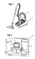
- FIG. 1 an inventive vacuum cleaner 1 is shown, is sucked in the dust-laden air via a floor nozzle and a Saugluft Unit 4, consisting of a length-adjustable suction pipe, a connector to a flexible suction hose into the interior of a housing of the vacuum cleaner 1.
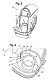
- a centrifugal separator 2 in the FIGS. 2 to 6 is shown in detail.
- the centrifugal separator 2 has a tubular air inlet duct 3, which adjoins the suction air duct 4 of the vacuum cleaner 1 in such a way that the air from the suction air duct 4 flows through it tangentially into the centrifugal separator 2. From there, the air passes into a substantially cylindrical separation chamber 5, in which, similar to a centrifuge according to the principle of centrifugal force, the dust from the air is deposited.
- An air outlet 6 of the centrifugal separator 2 is connected via a dip tube 7 with the separation chamber 5.
- an air guide means 8 in the form of a surface 9 is provided starting from the lower boundary surface 23 of the separation chamber 5, which results from continuous screwing 10 of a radius 14 of a longitudinal axis 11 of the separation chamber 4 about this longitudinal axis 11.
- the air guiding means 8 is formed in one piece with a designed as a pivotable lid housing part 19 of the centrifugal separator 2.
- the lid can be opened to clean the separation chamber 4.
- the lid also covers a collecting chamber, not shown, of the centrifugal separator 2, which can be emptied when the lid is opened.
- the threaded surface 9 of the air guide means begins from the mouth of the air inlet duct 3 in the direction of the screw 10 after about 2/3 of a full turn 12 about the longitudinal axis 11 of the centrifugal separator 2.
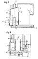
- the threaded surface 9 of the air duct 8 ends 24 after about 1 / 3 of a full turn 12 at the screw 10 facing edge of the mouth of the air inlet channel 3 and there has an axial extent 17 which corresponds approximately to the height of the mouth of the inlet channel 3. This can ensure that the deflected air does not collide with newly air flowing through the air inlet duct 3 and thereby undesirable turbulence. From the straight edge formed by the end 24 of the surface 9 of the air guiding means 8 extends radially, i.
- the surface 9 of the air guiding means 8 has a linear slope.
- the surface 9 extends in the radial direction of the separation chamber 5 from the central dip tube 7 up to the wall 20 of the cylindrical separation chamber 5.
- the centrifugal separator 2 operates as follows: Air flowing in through the air inlet duct 3 is directed onto the helical path by the air guiding means 8 and flows on this path in the direction of an obliquely arranged ejection surface 16 and an ejection 22 of the separating chamber 5 of the centrifugal separator 2 Centrifugal forces collects while the dust on the wall 20 of the separation chamber and moves there on a spiral path in the direction of ejection 22, through which he leaves the separation chamber 4 and enters the collection chamber. The air, however, undergoes a deflection at the level of the ejection 22 of the separation chamber 4 and leaves the separation chamber 4 through the dip tube 7 and the outlet 6 in the direction of the blower of the vacuum cleaner. 1
- the air guiding means 8 not only improves the dust separation but also reduces the noise generated by the centrifugal separator 2. This may be the comparison of FIGS. 7 and 8 are taken, in each of which the sound power of a centrifugal separator 2 is indicated as a function of frequency. It shows FIG. 7 the sound power of a centrifugal separator 2 without air guide means 8 and FIG. 8 However, it shows that a significant improvement can be achieved, especially in the case of the particularly unpleasant middle frequencies.
- the present invention facilitates with simple and constructive means the realization of a centrifugal separator 2 in which particularly a noise reduction and an increased volume flow are achieved. Furthermore, a higher overall efficiency and an increase in efficiency is achieved.
Landscapes
- Engineering & Computer Science (AREA)
- Mechanical Engineering (AREA)
- Filters For Electric Vacuum Cleaners (AREA)
- Cyclones (AREA)
Applications Claiming Priority (1)
| Application Number | Priority Date | Filing Date | Title |
|---|---|---|---|
| DE102008055047A DE102008055047A1 (de) | 2008-12-19 | 2008-12-19 | Staubsauger mit einem Fliehkraftabscheider |
Publications (3)
| Publication Number | Publication Date |
|---|---|
| EP2201878A2 true EP2201878A2 (fr) | 2010-06-30 |
| EP2201878A3 EP2201878A3 (fr) | 2011-09-07 |
| EP2201878B1 EP2201878B1 (fr) | 2013-06-05 |
Family
ID=42077318
Family Applications (1)
| Application Number | Title | Priority Date | Filing Date |
|---|---|---|---|
| EP20090178063 Not-in-force EP2201878B1 (fr) | 2008-12-19 | 2009-12-04 | Aspirateur doté d'un séparateur de force centrifuge |
Country Status (2)
| Country | Link |
|---|---|
| EP (1) | EP2201878B1 (fr) |
| DE (1) | DE102008055047A1 (fr) |
Cited By (2)
| Publication number | Priority date | Publication date | Assignee | Title |
|---|---|---|---|---|
| CN102485153A (zh) * | 2010-12-03 | 2012-06-06 | 乐金电子(天津)电器有限公司 | 具有异型进气道的吸尘器 |
| EP3735886A1 (fr) * | 2019-05-08 | 2020-11-11 | Robert Bosch GmbH | Appareil d'aspiration |
Family Cites Families (6)
| Publication number | Priority date | Publication date | Assignee | Title |
|---|---|---|---|---|
| DE2038045C3 (de) * | 1970-07-31 | 1981-12-10 | Siemens AG, 1000 Berlin und 8000 München | Zyklon |
| NL177187C (nl) * | 1974-01-16 | 1985-08-16 | Nederlandse Gasunie Nv | Inrichting voor het afscheiden van verontreinigingen uit gassen. |
| KR20010001213A (ko) | 1999-06-02 | 2001-01-05 | 구자홍 | 싸이클론 집진장치 |
| KR100607440B1 (ko) * | 2004-09-13 | 2006-08-02 | 삼성광주전자 주식회사 | 사이클론 집진장치 및 이를 구비한 진공 청소기 |
| DE102005056922A1 (de) | 2005-11-29 | 2007-05-31 | BSH Bosch und Siemens Hausgeräte GmbH | Staubsauger mit Fliehkraftabscheider |
| US20070209334A1 (en) * | 2006-03-10 | 2007-09-13 | Gbd Corp. | Vacuum cleaner with a removable screen |
-
2008
- 2008-12-19 DE DE102008055047A patent/DE102008055047A1/de not_active Withdrawn
-
2009
- 2009-12-04 EP EP20090178063 patent/EP2201878B1/fr not_active Not-in-force
Cited By (3)
| Publication number | Priority date | Publication date | Assignee | Title |
|---|---|---|---|---|
| CN102485153A (zh) * | 2010-12-03 | 2012-06-06 | 乐金电子(天津)电器有限公司 | 具有异型进气道的吸尘器 |
| CN102485153B (zh) * | 2010-12-03 | 2016-03-02 | 乐金电子(天津)电器有限公司 | 具有异型进气道的吸尘器 |
| EP3735886A1 (fr) * | 2019-05-08 | 2020-11-11 | Robert Bosch GmbH | Appareil d'aspiration |
Also Published As
| Publication number | Publication date |
|---|---|
| EP2201878B1 (fr) | 2013-06-05 |
| EP2201878A3 (fr) | 2011-09-07 |
| DE102008055047A1 (de) | 2010-06-24 |
Similar Documents
| Publication | Publication Date | Title |
|---|---|---|
| EP2866630B1 (fr) | Aspirateur avec un séparateur à tourbillon | |
| DE102012223983B4 (de) | Staubabscheideeinheit mit stufenweiser Staubabscheidung | |
| DE60106407T2 (de) | Vorrichtung zum abtrennen von teilchen aus einem fluidstrom | |
| DE102006012795B3 (de) | Entstaubungsvorrichtung für einen Staubsauger | |
| EP2201879A2 (fr) | Aspirateur doté des séparateurs de force centrifuge | |
| DE102004055897B4 (de) | Wirbelungs-Staubsammelvorrichtung und Staubsauger mit einer solchen Vorrichtung | |
| DE202006017010U1 (de) | Staubsammelvorrichtung sowie Staubsauger | |
| EP2198766B1 (fr) | Aspirateur doté d'un séparateur de force centrifuge | |
| WO2001012298A1 (fr) | Dispositif destine a separer des particules d'un fluide | |
| EP2201878B1 (fr) | Aspirateur doté d'un séparateur de force centrifuge | |
| EP2725955B1 (fr) | Tube séparateur à vortex avec dispositif de guidage rotative | |
| EP0346747B1 (fr) | Séparateur à cyclone | |
| DE102020114720A1 (de) | Zyklonsauger | |
| EP1956957B1 (fr) | Aspirateur pourvu d'un separateur centrifuge | |
| DE3034400A1 (de) | Fliehkraftabscheider zur abscheidung von schmutzteilchen und fluessigkeiten aus einem gasstrom | |
| DE102011087453A1 (de) | Staubsauger | |
| EP2725956B1 (fr) | Tube séparateur à vortex avec dispositif de guidage | |
| EP4120884B1 (fr) | Filtre et méthode de nettoyage | |
| DE102008055044B4 (de) | Staubsauger mit Fliehkraftabscheider | |
| DE102011078401B4 (de) | Verfahren zum zweifachen Abscheiden von Staub aus staubbeladener Saugluft | |
| DE102011087429A1 (de) | Nach dem Zentrifugalprinzip arbeitende Staubabscheideeinheit für einen Staubsauger | |
| WO2012013537A1 (fr) | Séparateur centrifuge avec surface déflectrice en amont | |
| EP2659821B1 (fr) | Dimensions d'un séparateur à tube vortex | |
| DE10317772A1 (de) | Staubabscheider | |
| WO2007131858A1 (fr) | Aspirateur pourvu d'au moins un dépoussiéreur centrifuge |
Legal Events
| Date | Code | Title | Description |
|---|---|---|---|
| PUAI | Public reference made under article 153(3) epc to a published international application that has entered the european phase |
Free format text: ORIGINAL CODE: 0009012 |
|
| AK | Designated contracting states |
Kind code of ref document: A2 Designated state(s): AT BE BG CH CY CZ DE DK EE ES FI FR GB GR HR HU IE IS IT LI LT LU LV MC MK MT NL NO PL PT RO SE SI SK SM TR |
|
| AX | Request for extension of the european patent |
Extension state: AL BA RS |
|
| PUAL | Search report despatched |
Free format text: ORIGINAL CODE: 0009013 |
|
| AK | Designated contracting states |
Kind code of ref document: A3 Designated state(s): AT BE BG CH CY CZ DE DK EE ES FI FR GB GR HR HU IE IS IT LI LT LU LV MC MK MT NL NO PL PT RO SE SI SK SM TR |
|
| AX | Request for extension of the european patent |
Extension state: AL BA RS |
|
| RIC1 | Information provided on ipc code assigned before grant |
Ipc: A47L 9/00 20060101ALI20110803BHEP Ipc: A47L 9/16 20060101AFI20110803BHEP |
|
| 17P | Request for examination filed |
Effective date: 20120307 |
|
| REG | Reference to a national code |
Ref country code: DE Ref legal event code: R079 Ref document number: 502009007286 Country of ref document: DE Free format text: PREVIOUS MAIN CLASS: A47L0009160000 Ipc: B04C0005103000 |
|
| GRAP | Despatch of communication of intention to grant a patent |
Free format text: ORIGINAL CODE: EPIDOSNIGR1 |
|
| RIC1 | Information provided on ipc code assigned before grant |
Ipc: A47L 9/00 20060101ALI20121211BHEP Ipc: B04C 5/103 20060101AFI20121211BHEP Ipc: A47L 9/16 20060101ALI20121211BHEP |
|
| GRAS | Grant fee paid |
Free format text: ORIGINAL CODE: EPIDOSNIGR3 |
|
| GRAA | (expected) grant |
Free format text: ORIGINAL CODE: 0009210 |
|
| AK | Designated contracting states |
Kind code of ref document: B1 Designated state(s): AT BE BG CH CY CZ DE DK EE ES FI FR GB GR HR HU IE IS IT LI LT LU LV MC MK MT NL NO PL PT RO SE SI SK SM TR |
|
| REG | Reference to a national code |
Ref country code: GB Ref legal event code: FG4D Free format text: NOT ENGLISH |
|
| REG | Reference to a national code |
Ref country code: CH Ref legal event code: EP |
|
| REG | Reference to a national code |
Ref country code: AT Ref legal event code: REF Ref document number: 615322 Country of ref document: AT Kind code of ref document: T Effective date: 20130615 |
|
| REG | Reference to a national code |
Ref country code: IE Ref legal event code: FG4D Free format text: LANGUAGE OF EP DOCUMENT: GERMAN |
|
| REG | Reference to a national code |
Ref country code: DE Ref legal event code: R096 Ref document number: 502009007286 Country of ref document: DE Effective date: 20130801 |
|
| PG25 | Lapsed in a contracting state [announced via postgrant information from national office to epo] |
Ref country code: ES Free format text: LAPSE BECAUSE OF FAILURE TO SUBMIT A TRANSLATION OF THE DESCRIPTION OR TO PAY THE FEE WITHIN THE PRESCRIBED TIME-LIMIT Effective date: 20130916 Ref country code: GR Free format text: LAPSE BECAUSE OF FAILURE TO SUBMIT A TRANSLATION OF THE DESCRIPTION OR TO PAY THE FEE WITHIN THE PRESCRIBED TIME-LIMIT Effective date: 20130906 Ref country code: LT Free format text: LAPSE BECAUSE OF FAILURE TO SUBMIT A TRANSLATION OF THE DESCRIPTION OR TO PAY THE FEE WITHIN THE PRESCRIBED TIME-LIMIT Effective date: 20130605 Ref country code: FI Free format text: LAPSE BECAUSE OF FAILURE TO SUBMIT A TRANSLATION OF THE DESCRIPTION OR TO PAY THE FEE WITHIN THE PRESCRIBED TIME-LIMIT Effective date: 20130605 Ref country code: SE Free format text: LAPSE BECAUSE OF FAILURE TO SUBMIT A TRANSLATION OF THE DESCRIPTION OR TO PAY THE FEE WITHIN THE PRESCRIBED TIME-LIMIT Effective date: 20130605 Ref country code: SI Free format text: LAPSE BECAUSE OF FAILURE TO SUBMIT A TRANSLATION OF THE DESCRIPTION OR TO PAY THE FEE WITHIN THE PRESCRIBED TIME-LIMIT Effective date: 20130605 Ref country code: NO Free format text: LAPSE BECAUSE OF FAILURE TO SUBMIT A TRANSLATION OF THE DESCRIPTION OR TO PAY THE FEE WITHIN THE PRESCRIBED TIME-LIMIT Effective date: 20130905 |
|
| REG | Reference to a national code |
Ref country code: NL Ref legal event code: VDEP Effective date: 20130605 |
|
| REG | Reference to a national code |
Ref country code: LT Ref legal event code: MG4D |
|
| PG25 | Lapsed in a contracting state [announced via postgrant information from national office to epo] |
Ref country code: PL Free format text: LAPSE BECAUSE OF FAILURE TO SUBMIT A TRANSLATION OF THE DESCRIPTION OR TO PAY THE FEE WITHIN THE PRESCRIBED TIME-LIMIT Effective date: 20130605 Ref country code: HR Free format text: LAPSE BECAUSE OF FAILURE TO SUBMIT A TRANSLATION OF THE DESCRIPTION OR TO PAY THE FEE WITHIN THE PRESCRIBED TIME-LIMIT Effective date: 20130605 Ref country code: BG Free format text: LAPSE BECAUSE OF FAILURE TO SUBMIT A TRANSLATION OF THE DESCRIPTION OR TO PAY THE FEE WITHIN THE PRESCRIBED TIME-LIMIT Effective date: 20130905 |
|
| PG25 | Lapsed in a contracting state [announced via postgrant information from national office to epo] |
Ref country code: LV Free format text: LAPSE BECAUSE OF FAILURE TO SUBMIT A TRANSLATION OF THE DESCRIPTION OR TO PAY THE FEE WITHIN THE PRESCRIBED TIME-LIMIT Effective date: 20130605 |
|
| PG25 | Lapsed in a contracting state [announced via postgrant information from national office to epo] |
Ref country code: SK Free format text: LAPSE BECAUSE OF FAILURE TO SUBMIT A TRANSLATION OF THE DESCRIPTION OR TO PAY THE FEE WITHIN THE PRESCRIBED TIME-LIMIT Effective date: 20130605 Ref country code: IS Free format text: LAPSE BECAUSE OF FAILURE TO SUBMIT A TRANSLATION OF THE DESCRIPTION OR TO PAY THE FEE WITHIN THE PRESCRIBED TIME-LIMIT Effective date: 20131005 Ref country code: CZ Free format text: LAPSE BECAUSE OF FAILURE TO SUBMIT A TRANSLATION OF THE DESCRIPTION OR TO PAY THE FEE WITHIN THE PRESCRIBED TIME-LIMIT Effective date: 20130605 Ref country code: EE Free format text: LAPSE BECAUSE OF FAILURE TO SUBMIT A TRANSLATION OF THE DESCRIPTION OR TO PAY THE FEE WITHIN THE PRESCRIBED TIME-LIMIT Effective date: 20130605 Ref country code: PT Free format text: LAPSE BECAUSE OF FAILURE TO SUBMIT A TRANSLATION OF THE DESCRIPTION OR TO PAY THE FEE WITHIN THE PRESCRIBED TIME-LIMIT Effective date: 20131007 |
|
| PG25 | Lapsed in a contracting state [announced via postgrant information from national office to epo] |
Ref country code: NL Free format text: LAPSE BECAUSE OF FAILURE TO SUBMIT A TRANSLATION OF THE DESCRIPTION OR TO PAY THE FEE WITHIN THE PRESCRIBED TIME-LIMIT Effective date: 20130605 Ref country code: RO Free format text: LAPSE BECAUSE OF FAILURE TO SUBMIT A TRANSLATION OF THE DESCRIPTION OR TO PAY THE FEE WITHIN THE PRESCRIBED TIME-LIMIT Effective date: 20130605 |
|
| PLBE | No opposition filed within time limit |
Free format text: ORIGINAL CODE: 0009261 |
|
| STAA | Information on the status of an ep patent application or granted ep patent |
Free format text: STATUS: NO OPPOSITION FILED WITHIN TIME LIMIT |
|
| PG25 | Lapsed in a contracting state [announced via postgrant information from national office to epo] |
Ref country code: DK Free format text: LAPSE BECAUSE OF FAILURE TO SUBMIT A TRANSLATION OF THE DESCRIPTION OR TO PAY THE FEE WITHIN THE PRESCRIBED TIME-LIMIT Effective date: 20130605 |
|
| 26N | No opposition filed |
Effective date: 20140306 |
|
| PG25 | Lapsed in a contracting state [announced via postgrant information from national office to epo] |
Ref country code: IT Free format text: LAPSE BECAUSE OF FAILURE TO SUBMIT A TRANSLATION OF THE DESCRIPTION OR TO PAY THE FEE WITHIN THE PRESCRIBED TIME-LIMIT Effective date: 20130605 |
|
| REG | Reference to a national code |
Ref country code: DE Ref legal event code: R097 Ref document number: 502009007286 Country of ref document: DE Effective date: 20140306 |
|
| BERE | Be: lapsed |
Owner name: BSH BOSCH UND SIEMENS HAUSGERATE G.M.B.H. Effective date: 20131231 |
|
| REG | Reference to a national code |
Ref country code: CH Ref legal event code: PL |
|
| PG25 | Lapsed in a contracting state [announced via postgrant information from national office to epo] |
Ref country code: LU Free format text: LAPSE BECAUSE OF FAILURE TO SUBMIT A TRANSLATION OF THE DESCRIPTION OR TO PAY THE FEE WITHIN THE PRESCRIBED TIME-LIMIT Effective date: 20131204 Ref country code: MC Free format text: LAPSE BECAUSE OF FAILURE TO SUBMIT A TRANSLATION OF THE DESCRIPTION OR TO PAY THE FEE WITHIN THE PRESCRIBED TIME-LIMIT Effective date: 20130605 |
|
| REG | Reference to a national code |
Ref country code: IE Ref legal event code: MM4A |
|
| PG25 | Lapsed in a contracting state [announced via postgrant information from national office to epo] |
Ref country code: CH Free format text: LAPSE BECAUSE OF NON-PAYMENT OF DUE FEES Effective date: 20131231 Ref country code: IE Free format text: LAPSE BECAUSE OF NON-PAYMENT OF DUE FEES Effective date: 20131204 Ref country code: BE Free format text: LAPSE BECAUSE OF NON-PAYMENT OF DUE FEES Effective date: 20131231 Ref country code: LI Free format text: LAPSE BECAUSE OF NON-PAYMENT OF DUE FEES Effective date: 20131231 |
|
| REG | Reference to a national code |
Ref country code: DE Ref legal event code: R081 Ref document number: 502009007286 Country of ref document: DE Owner name: BSH HAUSGERAETE GMBH, DE Free format text: FORMER OWNER: BSH BOSCH UND SIEMENS HAUSGERAETE GMBH, 81739 MUENCHEN, DE Effective date: 20150409 |
|
| PG25 | Lapsed in a contracting state [announced via postgrant information from national office to epo] |
Ref country code: SM Free format text: LAPSE BECAUSE OF FAILURE TO SUBMIT A TRANSLATION OF THE DESCRIPTION OR TO PAY THE FEE WITHIN THE PRESCRIBED TIME-LIMIT Effective date: 20130605 |
|
| PG25 | Lapsed in a contracting state [announced via postgrant information from national office to epo] |
Ref country code: CY Free format text: LAPSE BECAUSE OF FAILURE TO SUBMIT A TRANSLATION OF THE DESCRIPTION OR TO PAY THE FEE WITHIN THE PRESCRIBED TIME-LIMIT Effective date: 20130605 |
|
| PG25 | Lapsed in a contracting state [announced via postgrant information from national office to epo] |
Ref country code: HU Free format text: LAPSE BECAUSE OF FAILURE TO SUBMIT A TRANSLATION OF THE DESCRIPTION OR TO PAY THE FEE WITHIN THE PRESCRIBED TIME-LIMIT; INVALID AB INITIO Effective date: 20091204 Ref country code: MK Free format text: LAPSE BECAUSE OF FAILURE TO SUBMIT A TRANSLATION OF THE DESCRIPTION OR TO PAY THE FEE WITHIN THE PRESCRIBED TIME-LIMIT Effective date: 20130605 |
|
| PG25 | Lapsed in a contracting state [announced via postgrant information from national office to epo] |
Ref country code: MT Free format text: LAPSE BECAUSE OF FAILURE TO SUBMIT A TRANSLATION OF THE DESCRIPTION OR TO PAY THE FEE WITHIN THE PRESCRIBED TIME-LIMIT Effective date: 20130605 |
|
| REG | Reference to a national code |
Ref country code: FR Ref legal event code: CD Owner name: BSH HAUSGERATE GMBH, DE Effective date: 20151022 |
|
| REG | Reference to a national code |
Ref country code: FR Ref legal event code: PLFP Year of fee payment: 7 |
|
| REG | Reference to a national code |
Ref country code: AT Ref legal event code: MM01 Ref document number: 615322 Country of ref document: AT Kind code of ref document: T Effective date: 20141204 |
|
| PG25 | Lapsed in a contracting state [announced via postgrant information from national office to epo] |
Ref country code: AT Free format text: LAPSE BECAUSE OF NON-PAYMENT OF DUE FEES Effective date: 20141204 |
|
| REG | Reference to a national code |
Ref country code: FR Ref legal event code: PLFP Year of fee payment: 8 |
|
| REG | Reference to a national code |
Ref country code: FR Ref legal event code: PLFP Year of fee payment: 9 |
|
| PGFP | Annual fee paid to national office [announced via postgrant information from national office to epo] |
Ref country code: TR Payment date: 20181123 Year of fee payment: 10 Ref country code: GB Payment date: 20181219 Year of fee payment: 10 Ref country code: FR Payment date: 20181218 Year of fee payment: 10 |
|
| GBPC | Gb: european patent ceased through non-payment of renewal fee |
Effective date: 20191204 |
|
| PG25 | Lapsed in a contracting state [announced via postgrant information from national office to epo] |
Ref country code: GB Free format text: LAPSE BECAUSE OF NON-PAYMENT OF DUE FEES Effective date: 20191204 Ref country code: FR Free format text: LAPSE BECAUSE OF NON-PAYMENT OF DUE FEES Effective date: 20191231 |
|
| PG25 | Lapsed in a contracting state [announced via postgrant information from national office to epo] |
Ref country code: TR Free format text: LAPSE BECAUSE OF NON-PAYMENT OF DUE FEES Effective date: 20191204 |
|
| PGFP | Annual fee paid to national office [announced via postgrant information from national office to epo] |
Ref country code: DE Payment date: 20221231 Year of fee payment: 14 |
|
| P01 | Opt-out of the competence of the unified patent court (upc) registered |
Effective date: 20230504 |
|
| REG | Reference to a national code |
Ref country code: DE Ref legal event code: R119 Ref document number: 502009007286 Country of ref document: DE |
|
| PG25 | Lapsed in a contracting state [announced via postgrant information from national office to epo] |
Ref country code: DE Free format text: LAPSE BECAUSE OF NON-PAYMENT OF DUE FEES Effective date: 20240702 |
|
| PG25 | Lapsed in a contracting state [announced via postgrant information from national office to epo] |
Ref country code: DE Free format text: LAPSE BECAUSE OF NON-PAYMENT OF DUE FEES Effective date: 20240702 |