EP2202107B1 - Système de climatisation pour véhicule - Google Patents
Système de climatisation pour véhicule Download PDFInfo
- Publication number
- EP2202107B1 EP2202107B1 EP09180436A EP09180436A EP2202107B1 EP 2202107 B1 EP2202107 B1 EP 2202107B1 EP 09180436 A EP09180436 A EP 09180436A EP 09180436 A EP09180436 A EP 09180436A EP 2202107 B1 EP2202107 B1 EP 2202107B1
- Authority
- EP
- European Patent Office
- Prior art keywords
- vehicle
- temperature
- controller
- dew
- point
- Prior art date
- Legal status (The legal status is an assumption and is not a legal conclusion. Google has not performed a legal analysis and makes no representation as to the accuracy of the status listed.)
- Active
Links
Images



Classifications
-
- B—PERFORMING OPERATIONS; TRANSPORTING
- B60—VEHICLES IN GENERAL
- B60H—ARRANGEMENTS OF HEATING, COOLING, VENTILATING OR OTHER AIR-TREATING DEVICES SPECIALLY ADAPTED FOR PASSENGER OR GOODS SPACES OF VEHICLES
- B60H1/00—Heating, cooling or ventilating devices
- B60H1/00642—Control systems or circuits; Control members or indication devices for heating, cooling or ventilating devices
- B60H1/00735—Control systems or circuits characterised by their input, i.e. by the detection, measurement or calculation of particular conditions, e.g. signal treatment, dynamic models
- B60H1/00785—Control systems or circuits characterised by their input, i.e. by the detection, measurement or calculation of particular conditions, e.g. signal treatment, dynamic models by the detection of humidity or frost
-
- B—PERFORMING OPERATIONS; TRANSPORTING
- B60—VEHICLES IN GENERAL
- B60H—ARRANGEMENTS OF HEATING, COOLING, VENTILATING OR OTHER AIR-TREATING DEVICES SPECIALLY ADAPTED FOR PASSENGER OR GOODS SPACES OF VEHICLES
- B60H1/00—Heating, cooling or ventilating devices
- B60H1/00642—Control systems or circuits; Control members or indication devices for heating, cooling or ventilating devices
- B60H1/0073—Control systems or circuits characterised by particular algorithms or computational models, e.g. fuzzy logic or dynamic models
- B60H2001/00733—Computational models modifying user-set values
Definitions
- the present invention relates to an air conditioning system for a vehicle which is capable of defogging a window glass.
- Japanese Patent Application Laid-Open No. 7-232549 discloses an air conditioning apparatus for a vehicle which is adapted to suppress occurrence of fogging on a window glass (in the specification, a front windshield glass and a door glass are generically called "a window glass") in accordance with humidity in a passenger compartment of the vehicle.
- a fogging prevention determination value for determining whether or not a window glass is fogged is corrected in accordance with a rate of change in humidity in the passenger compartment in order to suppress occurrence of fogging on the window glass due to a delay in response of a humidity sensor upon a rapid rise in temperature in the passenger compartment.
- Patent Application US-A-2006/0289458 discloses an automotive vehicle defogging system according to the preamble of claims 1 and 9 to prevent dissipation of energy required to defog the automotive vehicle windshield.
- a surface temperature sensor mounted on the windshield detects the glass surface temperature.
- a humidity sensor spaced from the windshield glass by a predetermined distance detects the humidity around the windshield.
- a peripheral temperature sensor mounted inside from the windshield glass detects peripheral temperature around the glass. Dew point temperature is obtained in response to the detected humidity and a temperature value based on the temperatures detected by the surface and peripheral temperature sensors. The presence of fog is detected by comparing the dew point temperature with the surface temperature.
- the present disclosure relates to an air conditioning system for a vehicle, comprising a controller and a plurality of sensors in communication with the controller.
- the plurality of sensors include an interior temperature sensor for a vehicle interior, and an inner surface temperature sensor for a windshield.
- the controller is configured to determine a dew-point for the vehicle interior based on the sensed interior temperature and further configured to adjust the dew-point or the inner surface temperature based on a correction value.
- the controller performs a defogging operation when the inner surface temperature is less than the dew-point, wherein the dew-point or the inner surface temperature is adjusted value.
- the means for correction may at least partially be based on the difference between the heat resistance of the windshield and the heat resistance of a vehicle door glass.
- the air conditioning system of a vehicle comprises: a controller and a plurality of sensors in communication with the controller, wherein the plurality of sensors includes an interior temperature sensor for a vehicle interior, a relative humidity sensor for the vehicle interior, and an inner surface temperature sensor for a windshield.
- the controller is configured to determine a dew-point for the vehicle interior based on the sensed interior temperature and the sensed relative humidity.
- the controller is further configured to adjust the dew-point based on a correction value and is further configured to perform a defogging operation when the inner surface temperature is less than the adjusted dew-point.
- the present disclosure relates to an air conditioning system for a vehicle, comprising a controller and a plurality of sensors in communication with the controller.
- the plurality of sensors include a means for sensing a temperature of an interior of the vehicle, a means for sensing a relative humidity of the interior of the vehicle, and a means for sensing an inner surface temperature of a windshield of the vehicle.
- the controller is configured to determine a dew-point of the interior of the vehicle from the sensed interior temperature and the sensed relative humidity and further configured to adjust the dew-point using a means for correction.
- the controller performs a defogging operation when the sensed inner surface temperature is less than the adjusted dew-point.
- the defogging operation may include at least one of: adjusting the vehicle interior temperature; changing an air conditioning mode to a defroster mode; increasing a rotational speed of a blower fan to increase an amount of output from a plurality of defroster vents; increasing a temperature of air blown from the plurality of defroster vents; changing an air flow configuration from recirculation to introduction of outside ambient air; and blowing dehumidified air out of the plurality of defroster vents.
- the present disclosure relates to a method of defogging vehicle window glass.
- the method comprises: determining a temperature of a vehicle interior; determining a dew-point based on the determined temperature; determining an inner surface temperature of a windshield; adjusting the dew-point or the inner surface temperature based on a correction value; comparing the inner surface temperature to the dew-point; and performing a defogging operation when the inner surface temperature is less than the dew-point, wherein the dew-point or the inner surface temperature is adjusted value.
- the means for correction may at least partially be based on the difference between the heat resistance of the windshield and the heat resistance of a vehicle door glass.
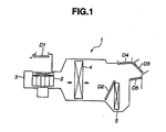
- Figure 1 is a schematic diagram illustrating a construction of an air conditioning system for a vehicle according to an exemplary embodiment of the present disclosure.
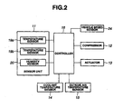
- FIG 2 is a block diagram illustrating a control system of the air conditioning system shown in Figure 1 .
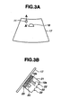
- Figure 3A is a diagram illustrating a layout of a sensor unit shown in Figure 2
- Figure 3B is a sectional view of the sensor unit along the line A-A of Figure 3A .
- Figure 4 is a flowchart illustrating an operation of defogging according an exemplary embodiment of the present disclosure.
- Figure 5 is a flowchart illustrating an operation to be performed after the flowchart shown in Figure 4 .
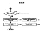
- Figure 6 is a flowchart illustrating an operation to be performed after the flowchart shown in Figure 5 .
- Figure 7 is a graph illustrating a relationship between predetermined time Ts and temperature Tam of an outside ambient air which may be used in step S17, as shown in Figure 5 .
- blower fan 2 may be rotated and an inside air (recirculated air) or an outside air (fresh air) may be sucked into air conditioning unit 3 through inside/outside air (recirculation/fresh air) switching door D1.
- a pressurized refrigerant may be transmitted to evaporator 4 by driving compressor 12 (see Figure 2 ), and the air sucked into air conditioning unit 3 may pass through evaporator 4 to thereby be dehumidified and cooled.
- the air passing through evaporator 4 may be divided into a part thereof which may pass through heater core 5 to thereby be heated, and the remaining part thereof which may bypass heater core 5 in the cooled condition, at a ratio according to an opening of air-mix door D2.
- the part that may pass through heater core 5 and the remaining part that may bypass heater core 5 may be mixed with each other downstream from heater core 5, so that an air-conditioned wind may be generated.
- the air-conditioned wind may be blown from a vent outlet port, a defroster outlet port, or a foot outlet port which may be exposed to an inside of a passenger compartment of the vehicle, via vent door D3, defroster door D4, and foot door D5, respectively, which may be opened and closed in accordance with a plurality of air conditioning modes.
- vent door D3, defroster door D4, or foot door D5 may be opened, respectively.
- a bilevel mode vent door D3 and foot door D5 may be opened.
- defroster door D4 and foot door D5 may be opened.
- Blower fan 2 and respective doors D1 to D5 may be driven by actuator 13 (see Figure 2 ), which may be a motor.
- a windshield defroster outlet port (a front defroster) may be disposed on an upper surface of an instrument panel near a lower end portion of front windshield glass 17 along a width direction of the vehicle. Blowing of the air-conditioned wind from the windshield defroster outlet port may remove fogging of front windshield glass 17.
- a side defroster outlet port (a side defroster) may be disposed at both end portions of the instrument panel in the width direction of the vehicle and may blow the air-conditioned wind toward a door glass.
- the control system for controlling vehicular air conditioning system 1 may include sensor unit 11, compressor 12, actuator 13, coolant temperature sensor 14, outside ambient air temperature sensor 15 all in communication with controller 16, as shown in Figure 2 .
- sensor unit 11 may, preferably, be disposed in a position on an inside surface of front windshield glass 17 which may be apart from the defroster outlet ports (at a lower side of the windshield) as far as possible and may be allowed to be free from exposure to the defroster wind.
- sensor unit 11 may be mounted to a portion of front windshield glass 17 which may be in the middle in the width direction of the vehicle and near a mounting site of rearview mirror 18 at an upper end portion of front windshield glass 17.
- sensor unit 11 may include temperature sensor 19a that may detect temperature Tga of vehicle inside air in the vicinity of front windshield glass 17, temperature sensor 19b that may detect temperature Tg of an inner surface of front windshield glass 17, and humidity sensor 20 that may detect humidity RH of the vehicle inside air in the vicinity of front windshield glass 17.
- Sensor unit 11 may include additional sensors and may also be located anywhere within the passenger compartment of the vehicle. Additionally, the sensors may be located throughout the passenger compartment, but may not be in a single sensor unit 11, but may be in multiple sensor units.
- Temperature sensors 19a and 19b and humidity sensor 20 may be disposed on an inside of generally box-shaped body 21. Holes 22, which may be provided for introducing the inside air to the sensor elements, may be formed in an upper surface of box-shaped body 21. Box-shaped body 21 may have an elastic resin film 23 on a bottom surface thereof, to which temperature sensor 19b may be fixed. Temperature sensors 19a and 19b may both, preferably, be constituted of thermistors, but may also be any means of measuring temperature. Temperature sensors 19a and 19b and humidity sensor 20 may output signals to controller 16 via a harness (not shown).
- coolant temperature sensor 14 may detect engine coolant temperature Tw in the vehicle, and outside ambient air temperature sensor 15 may detect temperature Tam of ambient air outside of the vehicle.
- vehicle speed sensor 24 may detect the speed of the vehicle and may output a value indicative of the detected vehicle speed to controller 16.
- Controller 16 may perform processing, as described later, based on the signals from these sensors and may output control signals to compressor 12 and actuator 13.
- Controller 16 may include a timer or clock, a memory for storing values output from the plurality of sensors and predetermined values, and a processor to calculate rates and compare values.
- controller 16 may receive other signals necessary for air conditioning control. For example, signals from a solar radiation sensor for detecting an amount of solar radiation, an air intake temperature sensor for detecting an air intake temperature of the air after passing through evaporator 4, and a setting device for setting a target temperature in the passenger compartment. Illustrations and further discussion of these sensors and device, or any other sensors and devices, are omitted, but may be incorporated into the air conditioning system described herein.
- the thus constructed vehicular air conditioning system 1 may suppress fogging of a window glass (particularly, a door glass) due to change in the outside air temperature by performing the following defogging operation, explained by referring to the flowcharts shown in Figures 4-6 .
- the flowcharts shown in Figures 4-6 illustrate a routine of the defogging operation which may be repeatedly performed by controller 16 at predetermined intervals.
- controller 16 may detect engine coolant temperature Tw(t) through coolant temperature sensor 14.
- controller 16 may detect inner surface temperature Tg(t) of front windshield glass 17 through temperature sensor 19b.
- controller 16 may detect inside air temperature Tga(t) in the vicinity of front windshield glass 17 through temperature sensor 19a.
- controller 16 may detect relative humidity RH(t) of the inside air in the vicinity of front windshield glass 17 through humidity sensor 20.
- controller 16 may detect temperature Tam(t) of ambient air outside of the vehicle through outside air temperature sensor 15.
- variable t is a time when the process is executed. Throughout the operation of the vehicle the process may be executed n times. The operation may be executed at any time interval, for example, every 0.5 seconds.
- controller 16 may determine whether or not engine coolant temperature Tw(t) detected in step S1 may be less than predetermined temperature A. As a result of the determination, in a case where engine coolant temperature Tw(t) may be less than predetermined engine coolant temperature A, controller 16 may determine that a period of time during which the vehicle may be in the OFF state may be long and there may be a high possibility that a temperature difference between the front window glass and the door glass may be increased. The routine may then proceed to step S12.
- controller 16 may determine that the period of time during which the vehicle may be in the OFF state may be short and there may be a low possibility that the temperature difference between the front window glass and the door glass may be increased. The routine may then proceed to step S18. Further, if the vehicle is already in the ON state, the controller 16 may determine that Tw(t) is greater than predetermined engine coolant temperature A. In this case, the routine may proceed to step S18.
- controller 16 may detect the engine coolant temperature in order to determine a length of the period of time during which the vehicle may be in the OFF state
- controller 16 may determine the length of the period of time during which the vehicle may be in the OFF state by using other methods such as actual measurement of the period of time during which the vehicle may be in the stopped state, which may be determined by the timer or clock of controller 16, or by an independent timer or clock.
- controller 16 may determine if the vehicle has been in the OFF state for a predetermined time. If it is greater than a predetermined time, then the routine may proceed to step S12. However, if it is less than a predetermined time, then the routine may proceed to step S18.
- controller 16 may determine whether or not vehicle speed V may be greater than predetermined speed B, and thereby may determine whether or not the vehicle may be started to shift from a stopped state to a moving state. At a time when vehicle speed V may become greater than predetermined speed B, controller 16 may determine that the vehicle may be started to shift from the stopped state to the moving state and proceed to step S13.
- controller 16 may determine a rate of change in the ambient air outside of the vehicle.
- the rate may be obtained by dividing the difference between a current detected temperature value and a previous detected temperature value by a time interval between the previous detection and the current detection. Specifically, outside ambient air temperature value Tam ( n-1 ) of the ambient air outside of the vehicle, which may have been detected in a previous processing in step S5, and outside ambient air temperature value Tam(n) of the ambient air outside of the vehicle, which may have been detected in a current processing in step S5, are compared. In this calculation, n is the current processing operation. This difference is then divided by the time interval between temperature measurements. Controller 16 may then compare the rate of change of the ambient air outside the vehicle with a predetermined value C.
- controller 16 may proceed to the processing in step S14.
- controller 16 may proceed to the processing in step S18.
- controller 16 may determine a rate of change in the inner surface temperature of front windshield 17.
- the rate may be obtained by dividing the difference between a current detected temperature value and a previous detected temperature value by a time interval between the previous detection and the current detection. Specifically, inner surface temperature value Tg ( n-1 ) of front windshield glass 17, which may have been detected in a previous processing in step S2, and inner surface temperature value Tg(n) of front windshield glass 17, which may have been detected in a current processing in step S2, are compared. This difference is then divided by the time interval between temperature measurements. Controller 16 may then compare the rate of change of the inner surface temperature with a predetermined value D.
- controller 16 may proceed to the processing in step S15.
- controller 16 may proceed to the processing in step S18.
- controller 16 may set correction value ⁇ for a fogging prevention determination value to predetermined value X, where X is non-zero.
- the predetermined value X may be preset in controller 16 and may be determined based on a difference in heat resistance between front windshield glass 17 and the door glass.
- controller 16 may switch the timer of controller 16, for counting an elapsed time (count value), from the OFF state to the ON state.
- controller 16 may determine whether or not a count value T of the timer may be greater than predetermined value Ts.
- Predetermined value Ts may be a value that may be decreased with an increase in temperature Tam(t) of the ambient air outside of the vehicle and may be set and adjusted by controller 16 accordingly, as illustrated in Figure 7 .
- controller 16 may proceed to the processing in step S18.
- S18 is processed when the time to reach predetermined time Ts may have elapsed since controller 16 set correction value ⁇ for the fogging prevention determination value to predetermined value X.
- controller 16 may proceed to the processing as detailed in Figure 6 , as detailed below.
- controller 16 may set correction value ⁇ for the fogging prevention determination value to zero. The process may then proceed to the procedure as shown in Figure 6 .
- controller 16 may compare inner surface temperature Tg(t) of front windshield glass 17, which may have been detected in step S2, with a threshold fogging prevention determination value.
- the threshold fogging prevention determination value may be obtained by adding correction value ⁇ to dew-point temperature Td(t) calculated in step S6. Controller 16 may then determine whether or not inner surface temperature Tg(t) of front windshield glass 17 may be less than the threshold fogging prevention determination value. In a case where inner surface temperature Tg(t) of front windshield glass 17 may be less than the threshold fogging prevention determination value controller 16 may proceed to the processing in step S22. On the other hand, in a case where inner surface temperature Tg(t) of front windshield glass 17 may be greater than the threshold fogging prevention determination value controller 16 may proceed to the processing in step S24.
- controller 16 may determine that there may be a possibility of fogging of the window glass and may set a fogging determination flag to the ON state.
- controller 16 may output a control signal to either one or both of compressor 12 and actuator 13 and may perform such an air conditioning operation as to defog the window glass (i.e., a defogging operation). Specifically, fogging on the window glass may be removed by decreasing the dew-point temperature near the inner surface of the window glass by blowing a dehumidified air across the window glass, or by increasing the outer surface temperature of the window glass by blowing out an air having a relatively high temperature across the window glass. Therefore, controller 16 may perform any one of the following operations (a)-(e) or any combination thereof, during step S23:
- step S23 the process may return to step S17 to determine if count value T of the timer is greater than predetermined value Ts. If the count value T is still less than predetermined time Ts, then the process repeats the steps of Figure 6 . However, if the count value T is greater than predetermined time Ts, then correction value ⁇ is set to zero and the steps of Figure 6 may be completed for a final processing.
- controller 16 may proceed to the processing in step S24. Controller 16 may determine that there may be no possibility of occurrence of fogging on the window glass, and may set the fogging determination flag to the OFF state.
- controller 16 may output control signals to compressor 12 and actuator 13 and may stop the defogging operation if the fogging determination flag was previously set to the ON state. Or, alternatively, if the defogging operation was previously set to the OFF state, the fogging determination flag may remain in the OFF state.
- controller 16 may determine whether or not temperature Tam of the outside air of the vehicle may be decreased by a value greater than the predetermined value. In a case where it may be determined that temperature Tam of the outside air of the vehicle may be decreased by a value greater than the predetermined value, controller 16 may set fogging prevention determination value Td + ⁇ so as to determine earlier that there may be a possibility of occurrence of fogging on the window glass. As a result, it may be possible to suppress fogging of the window glass with a change in temperature Tam of the outside air of the vehicle and ensure visibility.
- controller 16 may determine whether or not temperature Tam of the ambient air outside of the vehicle may be decreased by the value greater than the predetermined value when the vehicle may be started to shift from a stopped state to a running state. As a result, it may be possible to suppress occurrence of such an error that the defogging operation may be started in response to a drop in the ambient air temperature outside the vehicle which may-be caused by operation of a radiator cooling fan during idling of the vehicle.
- controller 16 may set the fogging prevention determination value by adding correction value ⁇ , which may be determined on the basis of a difference in heat resistance between the front windshield glass and the door glass of the vehicle, to the determined dew-point value.
- correction value ⁇ which may be determined on the basis of a difference in heat resistance between the front windshield glass and the door glass of the vehicle.
- controller 16 may correct the fogging prevention determination value. Therefore, it may be possible to suppress an error in determination of fogging.
- controller 16 may determine whether or not the temperature of the ambient air outside of the vehicle may be decreased by the value greater than the predetermined value. Therefore, it may be possible to suppress an error in determination of fogging.
- controller 16 may reset the fogging prevention determination value to a value in the ordinary state in response to lapse of predetermined time Ts that may be set in accordance with temperature Tam of the outside air of the vehicle.
- Ts predetermined time
- the time that may be taken to achieve a convergence of the temperature difference between the front windshield glass and the door glass in the vehicle running state and a convergence of the temperature difference between the front windshield glass and the door glass in the vehicle stopped state may be increased. Therefore, due to the above defogging operation as described herein, a correction time may be appropriately set to thereby suppress erroneous determination of occurrence of fogging.
- correction value ⁇ may be subtracted from detected inner surface temperature Tg(t) instead of being added to dew-point temperature Td(t) (threshold value of fogging prevention determination). Due to such a correction, the presence of a possibility of occurrence of fogging on the window glass may be determined earlier.
- this system advantageously allows a vehicle to prevent fogging of windows prior to impairment of visibility to a driver.
- the system allows for operation during initial start-up of the vehicle, and may be effective when driving a vehicle from a garage into the open air, where a sudden temperature difference may be present, so that fogging of windows may occur.
- the present system may be effective when a driver is operating a vehicle in a tunnel, and after leaving the tunnel, there is a sudden change in the temperature so that fogging of windows may occur.
- the present system may be effective when a driver experiences a sudden change in the weather, wherein fogging of the windows may occur due to changes in the temperature or humidity conditions.
Landscapes
- Physics & Mathematics (AREA)
- Thermal Sciences (AREA)
- Engineering & Computer Science (AREA)
- Mechanical Engineering (AREA)
- Air-Conditioning For Vehicles (AREA)
Claims (10)
- Système d'air conditionné (1) d'un véhicule, comprenant :un contrôleur (16) ; etune pluralité de capteurs en communication avec le contrôleur, dans lequel ;la pluralité de capteurs inclut un capteur de température intérieure (19a) pour un intérieur de véhicule, et un capteur de température de surface intérieure (19b) pour un pare-brise (17),le contrôleur (16) est configuré pour déterminer un point de rosée pour l'intérieur du véhicule sur la base de la température intérieure détectée,le contrôleur (16) est en outre configuré afin d'ajuster le point de rosée ou la température de surface intérieure sur la base d'une valeur de correction,le contrôleur (16) est en outre configuré afin d'effectuer une opération de désembuage quand la température de surface intérieure est inférieure au point de rosée, dans lequel le point de rosée ou la température de surface intérieure est une valeur ajustée, etcaractérisé en ce que la valeur de correction est basée sur la différence entre une résistance thermique du pare-brise (17) et une résistance thermique d'une vitre de porte de véhicule.
- Système d'air conditionné d'un véhicule selon la revendication 1, dans lequel :la pluralité de capteurs inclut un capteur de température extérieure (15) pour un air ambiant extérieur,le contrôleur (16) est en outre configuré afin de déterminer un taux de variation de la température extérieure, etle contrôleur (16) est en outre configuré afin d'effectuer l'ajustement du point de rosée ou de la température de surface intérieure quand le taux de variation déterminé de la température extérieure est supérieur à une valeur de température extérieure prédéterminée.
- Système d'air conditionné d'un véhicule selon la revendication 1, dans lequel l'opération de désembuage comprend au moins une étape consistant à :ajuster la température intérieure du véhicule ;changer un mode de conditionnement d'air en un mode de dégivreur ;augmenter une vitesse de rotation d'un ventilateur de soufflerie pour augmenter une quantité de rendement provenant d'une pluralité d'évents de dégivreur ;augmenter une température d'air soufflé depuis la pluralité d'évents de dégivreur ;changer une configuration d'écoulement d'air de la recirculation à l'introduction d'air ambiant extérieur ; etsouffler de l'air déshumidifié hors de la pluralité d'évents de dégivreur.
- Système d'air conditionné d'un véhicule selon la revendication 1, dans lequel :la pluralité de capteurs inclut un capteur de vitesse de véhicule (24),le contrôleur (16) est en outre configuré pour déterminer si le véhicule est dans un état arrêté ou un état en mouvement sur la base de la vitesse du véhicule, etle contrôleur (16) est en outre configuré afin de déterminer si la température de surface intérieure est inférieure au point de rosée ajusté quand le véhicule passe de l'état arrêté à l'état en mouvement.
- Système d'air conditionné d'un véhicule selon la revendication 1, dans lequel :le contrôleur (16) est en outre configuré pour déterminer un taux de variation de la température intérieure, etle contrôleur (16) est en outre configuré pour ajuster la valeur de correction quand le taux de variation déterminé de la température intérieure de véhicule est supérieur à une valeur intérieur de véhicule prédéterminée.
- Système d'air conditionné d'un véhicule selon la revendication 1, dans lequel :la pluralité de capteurs inclut un capteur de température de liquide de refroidissement du moteur (14), etle contrôleur (16) est en outre configuré afin de déterminer si la température de surface intérieure est inférieure au point de rosée ajusté quand la température du liquide de refroidissement du moteur détectée est inférieure à une valeur de liquide de refroidissement du moteur prédéterminée.
- Système d'air conditionné d'un véhicule selon la revendication 1, dans lequel :le contrôleur (16) est en outre configuré afin de compter le temps ; etle contrôleur (16) arrête d' ajuster le point de rosée quand un temps prédéterminé s'est écoulé.
- Système d'air conditionné d'un véhicule selon la revendication 7, dans lequel le contrôleur (16) diminue le temps prédéterminé à mesure que la température d'air ambiant extérieur augmente.
- Procédé de désembuage d'une vitre de fenêtre de véhicule, le procédé comprenant:déterminer une température d'un intérieur du véhicule ;déterminer un point de rosée sur la base de la température déterminée de l'intérieur du véhicule ;déterminer une température de surface intérieure d'un pare-brise (17) ;ajuster le point de rosée ou la température de surface intérieure sur la base d'une valeur de correction ;comparer la température de surface intérieure au point de rosée ;effectuer une opération de désembuage quand la température de surface intérieure est inférieure au point de rosée, dans lequel le point de rosée ou la température de surface intérieure est une valeur ajustée ; etcaractérisé en ce que la valeur de correction est basée au moins partiellement sur une différence entre une résistance thermique du pare-brise (16) et une résistance thermique d'une vitre de porte de véhicule.
- Procédé de désembuage d'une vitre de fenêtre de véhicule selon la revendication 9, dans lequel l'opération de désembuage comprend au moins une étape consistant à :ajuster la température de l'intérieur du véhicule ;changer un mode de conditionnement d'air en un mode de dégivreur ;augmenter une vitesse de rotation d'un ventilateur de soufflerie pour augmenter une quantité de rendement provenant d'une pluralité d'évents de dégivreur ;augmenter une température d'air soufflé depuis la pluralité d'évents de dégivreur ;changer une configuration d'écoulement d'air de la recirculation à l'introduction d'air ambiant extérieur ; etsouffler de l'air déshumidifié hors de la pluralité d'évents de dégivreur.
Applications Claiming Priority (2)
| Application Number | Priority Date | Filing Date | Title |
|---|---|---|---|
| JP2008332757 | 2008-12-26 | ||
| JP2009143365A JP4962530B2 (ja) | 2008-12-26 | 2009-06-16 | 車両用空調装置 |
Publications (2)
| Publication Number | Publication Date |
|---|---|
| EP2202107A1 EP2202107A1 (fr) | 2010-06-30 |
| EP2202107B1 true EP2202107B1 (fr) | 2011-07-20 |
Family
ID=42026343
Family Applications (1)
| Application Number | Title | Priority Date | Filing Date |
|---|---|---|---|
| EP09180436A Active EP2202107B1 (fr) | 2008-12-26 | 2009-12-22 | Système de climatisation pour véhicule |
Country Status (5)
| Country | Link |
|---|---|
| US (1) | US8733428B2 (fr) |
| EP (1) | EP2202107B1 (fr) |
| JP (1) | JP4962530B2 (fr) |
| CN (1) | CN101863211B (fr) |
| AT (1) | ATE516976T1 (fr) |
Cited By (1)
| Publication number | Priority date | Publication date | Assignee | Title |
|---|---|---|---|---|
| FR3157521A1 (fr) * | 2023-12-22 | 2025-06-27 | Stellantis Auto Sas | Procédé de gestion de l’entrée d’air dans un véhicule |
Families Citing this family (59)
| Publication number | Priority date | Publication date | Assignee | Title |
|---|---|---|---|---|
| US20100197406A1 (en) * | 2009-02-05 | 2010-08-05 | Ford Motor Company | System and method for vehicular ad-hoc gaming networking |
| US20110045842A1 (en) * | 2009-08-20 | 2011-02-24 | Ford Global Technologies, Llc | Method and System For Updating A Social Networking System Based On Vehicle Events |
| JP5038451B2 (ja) * | 2010-03-23 | 2012-10-03 | エンパイア テクノロジー ディベロップメント エルエルシー | 制御システム、制御方法、自動車 |
| JP5569425B2 (ja) * | 2010-05-20 | 2014-08-13 | 株式会社デンソー | 車両用空調装置 |
| DE102010038682B4 (de) * | 2010-07-30 | 2022-04-28 | Bayerische Motoren Werke Aktiengesellschaft | Verfahren zur Steuerung einer Heiz-Klimaanlage in einem Fahrzeug |
| JP5640536B2 (ja) * | 2010-08-05 | 2014-12-17 | 日産自動車株式会社 | 車両用空調装置 |
| KR101810420B1 (ko) * | 2010-09-09 | 2017-12-19 | 타쿠마사 와타나베 | 전기 자동차용 김서림 방지 및 공기 조화 시스템, 제습 유닛, 제습 카세트 및 제습 부재 |
| US8560202B2 (en) * | 2010-11-01 | 2013-10-15 | Ford Global Technologies, Llc | Method and apparatus for improved climate control function in a vehicle employing engine stop/start technology |
| US9451030B2 (en) * | 2011-02-18 | 2016-09-20 | Ford Global Technologies, Llc | Crowdsourced weather data collection and provision |
| US9447765B2 (en) | 2011-07-11 | 2016-09-20 | Ford Global Technologies, Llc | Powertrain delta current estimation method |
| US10480477B2 (en) | 2011-07-11 | 2019-11-19 | Ford Global Technologies, Llc | Electric current based engine auto stop inhibit algorithm and system implementing same |
| JP5494595B2 (ja) * | 2011-09-14 | 2014-05-14 | 株式会社デンソー | 車両用空調装置 |
| DE102011084278B4 (de) * | 2011-10-11 | 2022-12-22 | Ford Global Technologies, Llc | Verfahren und Vorrichtung zum Vermeiden des Beschlagens der Fensterscheiben eines Fahrzeugs |
| JP2013159228A (ja) * | 2012-02-06 | 2013-08-19 | Denso Corp | 車両用空調装置 |
| US9796359B2 (en) * | 2012-02-23 | 2017-10-24 | The Raymond Corporation | Method and apparatus for removing and preventing lens surface contamination on a vehicle lens |
| US9303613B2 (en) | 2012-02-24 | 2016-04-05 | Ford Global Technologies, Llc | Control of vehicle electrical loads during engine auto stop event |
| CN103359072A (zh) * | 2012-03-31 | 2013-10-23 | 杭州三花研究院有限公司 | 一种汽车空气调节系统及其空气调节方法 |
| US20140004782A1 (en) * | 2012-06-29 | 2014-01-02 | Ford Global Technologies, Llc | System and method of controlling ventilation of a passenger compartment of a vehicle |
| US8893517B2 (en) * | 2012-08-27 | 2014-11-25 | Ford Global Technologies, Llc | Vehicle air handling system |
| US9008891B2 (en) * | 2012-10-03 | 2015-04-14 | GM Global Technology Operations LLC | Temperature sensor rationalization |
| CN103963597B (zh) * | 2013-01-31 | 2017-10-31 | 浙江三花汽车零部件有限公司 | 汽车自动空调控制器 |
| US8892291B2 (en) | 2013-03-12 | 2014-11-18 | Ford Global Technologies, Llc | Vehicle mass detection system |
| CN104070959B (zh) * | 2013-03-28 | 2017-10-24 | 浙江三花汽车零部件有限公司 | 得到环境温度的方法及其控制系统 |
| CN103318140B (zh) * | 2013-05-28 | 2016-01-27 | 奇瑞汽车股份有限公司 | 一种汽车前挡风玻璃内表面自动除雾系统 |
| JP6083329B2 (ja) * | 2013-06-18 | 2017-02-22 | マツダ株式会社 | 車両用空調制御装置 |
| CN103386874B (zh) * | 2013-08-02 | 2015-06-17 | 苏州贝昂科技有限公司 | 一种车载空气净化器控制装置及方法 |
| US9248824B2 (en) | 2014-01-24 | 2016-02-02 | Ford Global Technologies, Llc | Rear defrost control in stop/start vehicle |
| CN103847463B (zh) * | 2014-03-26 | 2016-02-10 | 惠州华阳通用电子有限公司 | 一种自动防止汽车起雾的控制方法 |
| US9724980B2 (en) | 2014-08-20 | 2017-08-08 | Ford Global Technologies, Llc | Windshield defogging system and method |
| US9834310B2 (en) | 2014-12-17 | 2017-12-05 | The Boeing Company | Automatic activation of a fog protection system onboard a vehicle |
| CN104527372A (zh) * | 2015-01-16 | 2015-04-22 | 北京汽车研究总院有限公司 | 一种汽车空调自动除雾系统及汽车 |
| FR3035177B1 (fr) * | 2015-04-16 | 2022-10-07 | Valeo Vision | Dispositif de commande d'un systeme d'eclairage et/ou de signalisation de vehicule |
| US9975401B2 (en) * | 2015-06-12 | 2018-05-22 | Ford Global Technologies, Llc | Method and apparatus for avoiding windowpane misting in a vehicle |
| US9975400B2 (en) * | 2015-06-18 | 2018-05-22 | Ford Global Technologies, Llc | Method of controlling climate in a parked vehicle |
| CN106476562A (zh) * | 2015-08-31 | 2017-03-08 | 株式会社电装 | 车辆用空调装置以及车辆用空调控制装置 |
| US20170106721A1 (en) * | 2015-10-15 | 2017-04-20 | Ford Global Technologies, Llc | Energy-efficient vehicle window defogging and prevention of re-freezing |
| CN105346355B (zh) * | 2015-11-16 | 2017-12-05 | 兵器工业卫生研究所 | 地面装备舱室微环境一体化控制系统 |
| US10293657B2 (en) | 2016-02-25 | 2019-05-21 | Toyota Motor Engineering & Manufacturing North America, Inc. | Vehicle automatic defrost system and method |
| US10196994B2 (en) | 2016-05-16 | 2019-02-05 | Ford Global Technologies, Llc | Powertrain control system |
| US10246073B2 (en) | 2016-05-16 | 2019-04-02 | Ford Global Technologies, Llc | Control system for a hybrid-electric vehicle |
| US10759255B2 (en) * | 2016-07-20 | 2020-09-01 | Ford Global Technologies, Llc | Autonomous-vehicle climate-control system |
| US20190098705A1 (en) * | 2017-09-25 | 2019-03-28 | Ford Global Technologies, Llc | Windshield defrost |
| US11267314B2 (en) * | 2017-11-15 | 2022-03-08 | Ford Global Technologies, Llc | Enhanced vehicle window anti-fogging strategy |
| US10737551B2 (en) | 2017-11-30 | 2020-08-11 | Nissan North America, Inc. | Vehicle air handling system |
| US11161455B2 (en) * | 2017-11-30 | 2021-11-02 | Ford Global Technologies, Llc | Defrost/defog system side mirror with peltier element |
| JP2019099045A (ja) * | 2017-12-06 | 2019-06-24 | 株式会社日本クライメイトシステムズ | 車両用空調装置 |
| US10752215B2 (en) * | 2018-05-23 | 2020-08-25 | Ford Global Technologies, Llc | Vehicle automatic defrost system and control method for external window surface |
| JP7066645B2 (ja) * | 2019-01-23 | 2022-05-13 | 本田技研工業株式会社 | 移動体用制御装置 |
| JP7066650B2 (ja) * | 2019-03-05 | 2022-05-13 | 本田技研工業株式会社 | 曇り抑制装置およびその制御方法 |
| DE112020001244T5 (de) * | 2019-03-15 | 2021-12-02 | AGC Inc. | Fensterglassystem und Fensterglas |
| US11052725B2 (en) * | 2019-09-26 | 2021-07-06 | Ford Global Technologies, Llc | Automatic windshield defrosting system |
| US12151535B2 (en) | 2020-03-25 | 2024-11-26 | Pony Ai Inc. | Systems and methods for cooling components of a vehicle |
| CN111497555B (zh) * | 2020-04-24 | 2022-05-17 | 重庆长安汽车股份有限公司 | 汽车空调采暖方法 |
| CN112158166B (zh) * | 2020-09-30 | 2023-03-28 | 重庆长安汽车股份有限公司 | 一种汽车自动除雾的控制方法及汽车 |
| EP4219198B1 (fr) * | 2020-10-31 | 2025-01-01 | Shenzhen Yinwang Intelligent Technologies Co., Ltd. | Unité de climatisation pour une automobile, procédé de commande de ladite unité de climatisation et contrôleur de ladite unité de climatisation |
| CN114590228A (zh) * | 2020-12-04 | 2022-06-07 | 纬湃汽车电子(长春)有限公司 | 用于运行机动车车载空调系统的方法及除雾系统 |
| DE102021201377A1 (de) * | 2021-02-15 | 2022-08-18 | Volkswagen Aktiengesellschaft | Verfahren zum Einleiten eines Abtauprozesses eines Wärmeübertragers einer Wärmepumpe eines Kraftfahrzeuges |
| CN114274736B (zh) * | 2022-02-16 | 2023-11-21 | 一汽解放汽车有限公司 | 汽车空调防雾控制方法、装置、设备、存储介质 |
| CN115195400B (zh) * | 2022-07-14 | 2026-02-24 | 东风汽车集团股份有限公司 | 基于内外循环风门的纯电动汽车节能控制系统、方法及介质 |
Family Cites Families (34)
| Publication number | Priority date | Publication date | Assignee | Title |
|---|---|---|---|---|
| JPS5948169B2 (ja) * | 1978-10-02 | 1984-11-24 | 株式会社デンソー | 車両用空調制御方法およびその装置 |
| US4744511A (en) * | 1985-11-27 | 1988-05-17 | Nippondenso Co., Ltd. | Air conditioner for automobiles |
| JPS63180514A (ja) * | 1987-01-21 | 1988-07-25 | Hitachi Ltd | 車両用空調装置 |
| DE10320340A1 (de) * | 2003-05-07 | 2004-12-09 | J. Eberspächer GmbH & Co. KG | Heizsystem für ein Fahrzeug |
| JP3201125B2 (ja) | 1994-02-25 | 2001-08-20 | 株式会社デンソー | 車両用空調装置 |
| US5511724A (en) * | 1994-11-23 | 1996-04-30 | Delco Electronics Corporation | Adaptive climate control system |
| JP3334410B2 (ja) * | 1995-03-14 | 2002-10-15 | 株式会社デンソー | 車両用空調装置 |
| JP2001334820A (ja) * | 2000-05-29 | 2001-12-04 | Denso Corp | 車両用空調装置 |
| US6422062B1 (en) * | 2000-08-29 | 2002-07-23 | Delphi Technologies, Inc. | Integrated glass fog sensor unit |
| JP2002370521A (ja) * | 2001-06-15 | 2002-12-24 | Denso Corp | 車両用空調装置 |
| DE10153000C1 (de) * | 2001-10-26 | 2003-04-30 | Preh Elektro Feinmechanik | Verfahren zur Beschlagsvermeidung an Scheiben eines Kraftfahrzeuges |
| DE10257587B3 (de) * | 2002-12-09 | 2004-04-15 | Daimlerchrysler Ag | Verfahren zur Regelung einer Klimaanlage für ein Fahrzeug mit verschließbaren Karosserieöffnungen |
| JP2005059797A (ja) * | 2003-08-19 | 2005-03-10 | Denso Corp | 車両用空調装置 |
| JP4314933B2 (ja) * | 2003-08-27 | 2009-08-19 | 株式会社デンソー | 車両用空調装置 |
| JP2005186919A (ja) * | 2003-12-04 | 2005-07-14 | Keihin Corp | 車両用空調装置 |
| US7197927B2 (en) * | 2004-02-16 | 2007-04-03 | Sitronic Gesellschaft für Elektrotechnische Ausrustüng mbH & Co. KG | Sensor for determining the interior humidity and fogging up tendency and fastening device of the sensor |
| US7392838B2 (en) * | 2004-06-30 | 2008-07-01 | Honda Motor Co., Ltd. | System and method for vehicle defogging condition calculation and control |
| CN100581858C (zh) * | 2004-09-15 | 2010-01-20 | 麦格纳唐纳利工程有限公司 | 一种车辆环境控制系统 |
| DE102004045839B3 (de) * | 2004-09-22 | 2006-02-23 | Sitronic Gesellschaft für elektrotechnische Ausrüstung mbH. & Co. KG | Verfahren zur Bestimmung des Auflösungszeitpunkts eines Scheibenbeschlags |
| JP4534973B2 (ja) * | 2005-11-29 | 2010-09-01 | 株式会社デンソー | 窓曇り検出装置 |
| KR101170575B1 (ko) | 2005-05-17 | 2012-08-01 | 한라공조주식회사 | 자동차의 디포깅 장치 및 그 제어방법 |
| JP2006335117A (ja) * | 2005-05-31 | 2006-12-14 | Denso Corp | 車両用空調装置 |
| KR100815298B1 (ko) * | 2005-12-13 | 2008-03-19 | 현대자동차주식회사 | 차량의 자동 습기제거 시스템 및 그의 제어방법 |
| US7832223B2 (en) * | 2006-01-10 | 2010-11-16 | Cnh America Llc | Controller area network based climate control system for a self-propelled work machine and method of operation of the same |
| JP4736872B2 (ja) * | 2006-03-10 | 2011-07-27 | 株式会社デンソー | 空調装置 |
| JP2007253886A (ja) * | 2006-03-24 | 2007-10-04 | Denso Corp | 車両用空調装置 |
| JP4816212B2 (ja) * | 2006-04-10 | 2011-11-16 | 日産自動車株式会社 | ガラス温度検出装置、窓曇り検出装置、車両用空調装置および窓曇り検出方法 |
| JP5012193B2 (ja) * | 2006-06-06 | 2012-08-29 | 株式会社デンソー | 車両用空調装置 |
| CN200946884Y (zh) * | 2006-07-06 | 2007-09-12 | 湖北美标汽车制冷系统有限公司 | 卡车空调系统的自动控制装置 |
| DE602006008844D1 (de) * | 2006-07-19 | 2009-10-15 | Sensirion Holding Ag | Feuchtigkeitsfühler zur Ermittlung von Beschlag auf einem Fenster |
| JP4858305B2 (ja) * | 2006-09-15 | 2012-01-18 | 株式会社デンソー | 湿度検出装置および車両用空調装置 |
| US7696710B2 (en) * | 2006-10-30 | 2010-04-13 | Agc Automotive Americas R&D, Inc. | Method of sensing an amount of moisture on a surface of a substrate with temperature compensation |
| FR2912688B1 (fr) * | 2007-02-16 | 2009-08-28 | Renault Soc Par Actions Simpli | Procede de regulation du confort thermique pour un vehicule a arret et depart du moteur |
| JP2011246083A (ja) * | 2010-05-31 | 2011-12-08 | Suzuki Motor Corp | 車両用空調装置 |
-
2009
- 2009-06-16 JP JP2009143365A patent/JP4962530B2/ja active Active
- 2009-12-22 AT AT09180436T patent/ATE516976T1/de not_active IP Right Cessation
- 2009-12-22 EP EP09180436A patent/EP2202107B1/fr active Active
- 2009-12-23 US US12/646,663 patent/US8733428B2/en active Active
- 2009-12-25 CN CN2009102470509A patent/CN101863211B/zh active Active
Cited By (1)
| Publication number | Priority date | Publication date | Assignee | Title |
|---|---|---|---|---|
| FR3157521A1 (fr) * | 2023-12-22 | 2025-06-27 | Stellantis Auto Sas | Procédé de gestion de l’entrée d’air dans un véhicule |
Also Published As
| Publication number | Publication date |
|---|---|
| EP2202107A1 (fr) | 2010-06-30 |
| US20100163220A1 (en) | 2010-07-01 |
| JP4962530B2 (ja) | 2012-06-27 |
| JP2010168026A (ja) | 2010-08-05 |
| CN101863211B (zh) | 2013-03-13 |
| US8733428B2 (en) | 2014-05-27 |
| CN101863211A (zh) | 2010-10-20 |
| ATE516976T1 (de) | 2011-08-15 |
Similar Documents
| Publication | Publication Date | Title |
|---|---|---|
| EP2202107B1 (fr) | Système de climatisation pour véhicule | |
| EP1844964B1 (fr) | Système de détection de la température de vitre, système de détection de buée sur la fenêtre, système de climatisation pour véhicules et procédé de détection de buée sur la fenêtre | |
| JP4317902B2 (ja) | 車両用空調装置 | |
| JP4311270B2 (ja) | 車両用空調装置 | |
| JP3508485B2 (ja) | 車両用空調装置 | |
| US7143590B2 (en) | Vehicle air conditioner | |
| JP4310902B2 (ja) | 車両用空調装置 | |
| JP4403652B2 (ja) | 車両用空調装置 | |
| KR101427231B1 (ko) | 차량용 공조시스템의 디포깅장치 | |
| JP3781612B2 (ja) | 車両用空調装置 | |
| JP2002137630A (ja) | 車両用オートエアコン制御装置 | |
| KR20160013310A (ko) | 차량용 공조장치 | |
| JP4706774B2 (ja) | 車両用空調装置 | |
| JP3169063B2 (ja) | 車両用空調装置 | |
| JP2003182351A (ja) | 車両用空調装置 | |
| JP3890963B2 (ja) | 車両用防曇装置 | |
| JP3861805B2 (ja) | 車両用空調装置 | |
| JP3969128B2 (ja) | 車両用空調装置 | |
| JP2006056450A (ja) | 車両用内外気切換装置 | |
| JP2005324638A (ja) | 車両用空調装置 | |
| JP2009248608A (ja) | 車両用空調装置 | |
| JP3533723B2 (ja) | 車両用空気調和装置 | |
| JP2004255898A (ja) | 車両用空調装置およびその制御プログラム | |
| JP3922158B2 (ja) | 車両用空調装置 | |
| JP2004050926A (ja) | 車両用空調装置 |
Legal Events
| Date | Code | Title | Description |
|---|---|---|---|
| PUAI | Public reference made under article 153(3) epc to a published international application that has entered the european phase |
Free format text: ORIGINAL CODE: 0009012 |
|
| AK | Designated contracting states |
Kind code of ref document: A1 Designated state(s): AT BE BG CH CY CZ DE DK EE ES FI FR GB GR HR HU IE IS IT LI LT LU LV MC MK MT NL NO PL PT RO SE SI SK SM TR |
|
| AX | Request for extension of the european patent |
Extension state: AL BA RS |
|
| GRAP | Despatch of communication of intention to grant a patent |
Free format text: ORIGINAL CODE: EPIDOSNIGR1 |
|
| 17P | Request for examination filed |
Effective date: 20101230 |
|
| RIC1 | Information provided on ipc code assigned before grant |
Ipc: B60S 1/54 20060101ALI20110202BHEP Ipc: B60H 1/00 20060101AFI20110202BHEP |
|
| GRAS | Grant fee paid |
Free format text: ORIGINAL CODE: EPIDOSNIGR3 |
|
| GRAA | (expected) grant |
Free format text: ORIGINAL CODE: 0009210 |
|
| AK | Designated contracting states |
Kind code of ref document: B1 Designated state(s): AT BE BG CH CY CZ DE DK EE ES FI FR GB GR HR HU IE IS IT LI LT LU LV MC MK MT NL NO PL PT RO SE SI SK SM TR |
|
| REG | Reference to a national code |
Ref country code: GB Ref legal event code: FG4D |
|
| REG | Reference to a national code |
Ref country code: CH Ref legal event code: EP |
|
| REG | Reference to a national code |
Ref country code: DE Ref legal event code: R096 Ref document number: 602009001877 Country of ref document: DE Effective date: 20110915 |
|
| REG | Reference to a national code |
Ref country code: NL Ref legal event code: VDEP Effective date: 20110720 |
|
| REG | Reference to a national code |
Ref country code: AT Ref legal event code: MK05 Ref document number: 516976 Country of ref document: AT Kind code of ref document: T Effective date: 20110720 |
|
| PG25 | Lapsed in a contracting state [announced via postgrant information from national office to epo] |
Ref country code: IS Free format text: LAPSE BECAUSE OF FAILURE TO SUBMIT A TRANSLATION OF THE DESCRIPTION OR TO PAY THE FEE WITHIN THE PRESCRIBED TIME-LIMIT Effective date: 20111120 Ref country code: HR Free format text: LAPSE BECAUSE OF FAILURE TO SUBMIT A TRANSLATION OF THE DESCRIPTION OR TO PAY THE FEE WITHIN THE PRESCRIBED TIME-LIMIT Effective date: 20110720 Ref country code: BE Free format text: LAPSE BECAUSE OF FAILURE TO SUBMIT A TRANSLATION OF THE DESCRIPTION OR TO PAY THE FEE WITHIN THE PRESCRIBED TIME-LIMIT Effective date: 20110720 Ref country code: NO Free format text: LAPSE BECAUSE OF FAILURE TO SUBMIT A TRANSLATION OF THE DESCRIPTION OR TO PAY THE FEE WITHIN THE PRESCRIBED TIME-LIMIT Effective date: 20111020 Ref country code: LT Free format text: LAPSE BECAUSE OF FAILURE TO SUBMIT A TRANSLATION OF THE DESCRIPTION OR TO PAY THE FEE WITHIN THE PRESCRIBED TIME-LIMIT Effective date: 20110720 Ref country code: SE Free format text: LAPSE BECAUSE OF FAILURE TO SUBMIT A TRANSLATION OF THE DESCRIPTION OR TO PAY THE FEE WITHIN THE PRESCRIBED TIME-LIMIT Effective date: 20110720 Ref country code: NL Free format text: LAPSE BECAUSE OF FAILURE TO SUBMIT A TRANSLATION OF THE DESCRIPTION OR TO PAY THE FEE WITHIN THE PRESCRIBED TIME-LIMIT Effective date: 20110720 Ref country code: PT Free format text: LAPSE BECAUSE OF FAILURE TO SUBMIT A TRANSLATION OF THE DESCRIPTION OR TO PAY THE FEE WITHIN THE PRESCRIBED TIME-LIMIT Effective date: 20111121 Ref country code: FI Free format text: LAPSE BECAUSE OF FAILURE TO SUBMIT A TRANSLATION OF THE DESCRIPTION OR TO PAY THE FEE WITHIN THE PRESCRIBED TIME-LIMIT Effective date: 20110720 |
|
| PG25 | Lapsed in a contracting state [announced via postgrant information from national office to epo] |
Ref country code: SI Free format text: LAPSE BECAUSE OF FAILURE TO SUBMIT A TRANSLATION OF THE DESCRIPTION OR TO PAY THE FEE WITHIN THE PRESCRIBED TIME-LIMIT Effective date: 20110720 Ref country code: PL Free format text: LAPSE BECAUSE OF FAILURE TO SUBMIT A TRANSLATION OF THE DESCRIPTION OR TO PAY THE FEE WITHIN THE PRESCRIBED TIME-LIMIT Effective date: 20110720 Ref country code: AT Free format text: LAPSE BECAUSE OF FAILURE TO SUBMIT A TRANSLATION OF THE DESCRIPTION OR TO PAY THE FEE WITHIN THE PRESCRIBED TIME-LIMIT Effective date: 20110720 Ref country code: CY Free format text: LAPSE BECAUSE OF FAILURE TO SUBMIT A TRANSLATION OF THE DESCRIPTION OR TO PAY THE FEE WITHIN THE PRESCRIBED TIME-LIMIT Effective date: 20110720 Ref country code: GR Free format text: LAPSE BECAUSE OF FAILURE TO SUBMIT A TRANSLATION OF THE DESCRIPTION OR TO PAY THE FEE WITHIN THE PRESCRIBED TIME-LIMIT Effective date: 20111021 Ref country code: LV Free format text: LAPSE BECAUSE OF FAILURE TO SUBMIT A TRANSLATION OF THE DESCRIPTION OR TO PAY THE FEE WITHIN THE PRESCRIBED TIME-LIMIT Effective date: 20110720 |
|
| PG25 | Lapsed in a contracting state [announced via postgrant information from national office to epo] |
Ref country code: SK Free format text: LAPSE BECAUSE OF FAILURE TO SUBMIT A TRANSLATION OF THE DESCRIPTION OR TO PAY THE FEE WITHIN THE PRESCRIBED TIME-LIMIT Effective date: 20110720 Ref country code: CZ Free format text: LAPSE BECAUSE OF FAILURE TO SUBMIT A TRANSLATION OF THE DESCRIPTION OR TO PAY THE FEE WITHIN THE PRESCRIBED TIME-LIMIT Effective date: 20110720 |
|
| PLBE | No opposition filed within time limit |
Free format text: ORIGINAL CODE: 0009261 |
|
| STAA | Information on the status of an ep patent application or granted ep patent |
Free format text: STATUS: NO OPPOSITION FILED WITHIN TIME LIMIT |
|
| PG25 | Lapsed in a contracting state [announced via postgrant information from national office to epo] |
Ref country code: RO Free format text: LAPSE BECAUSE OF FAILURE TO SUBMIT A TRANSLATION OF THE DESCRIPTION OR TO PAY THE FEE WITHIN THE PRESCRIBED TIME-LIMIT Effective date: 20110720 Ref country code: IT Free format text: LAPSE BECAUSE OF FAILURE TO SUBMIT A TRANSLATION OF THE DESCRIPTION OR TO PAY THE FEE WITHIN THE PRESCRIBED TIME-LIMIT Effective date: 20110720 Ref country code: EE Free format text: LAPSE BECAUSE OF FAILURE TO SUBMIT A TRANSLATION OF THE DESCRIPTION OR TO PAY THE FEE WITHIN THE PRESCRIBED TIME-LIMIT Effective date: 20110720 |
|
| 26N | No opposition filed |
Effective date: 20120423 |
|
| PG25 | Lapsed in a contracting state [announced via postgrant information from national office to epo] |
Ref country code: DK Free format text: LAPSE BECAUSE OF FAILURE TO SUBMIT A TRANSLATION OF THE DESCRIPTION OR TO PAY THE FEE WITHIN THE PRESCRIBED TIME-LIMIT Effective date: 20110720 |
|
| PG25 | Lapsed in a contracting state [announced via postgrant information from national office to epo] |
Ref country code: MC Free format text: LAPSE BECAUSE OF NON-PAYMENT OF DUE FEES Effective date: 20111231 |
|
| REG | Reference to a national code |
Ref country code: DE Ref legal event code: R097 Ref document number: 602009001877 Country of ref document: DE Effective date: 20120423 |
|
| REG | Reference to a national code |
Ref country code: IE Ref legal event code: MM4A |
|
| PG25 | Lapsed in a contracting state [announced via postgrant information from national office to epo] |
Ref country code: IE Free format text: LAPSE BECAUSE OF NON-PAYMENT OF DUE FEES Effective date: 20111222 |
|
| PG25 | Lapsed in a contracting state [announced via postgrant information from national office to epo] |
Ref country code: MK Free format text: LAPSE BECAUSE OF FAILURE TO SUBMIT A TRANSLATION OF THE DESCRIPTION OR TO PAY THE FEE WITHIN THE PRESCRIBED TIME-LIMIT Effective date: 20110720 Ref country code: MT Free format text: LAPSE BECAUSE OF FAILURE TO SUBMIT A TRANSLATION OF THE DESCRIPTION OR TO PAY THE FEE WITHIN THE PRESCRIBED TIME-LIMIT Effective date: 20110720 |
|
| PG25 | Lapsed in a contracting state [announced via postgrant information from national office to epo] |
Ref country code: SM Free format text: LAPSE BECAUSE OF FAILURE TO SUBMIT A TRANSLATION OF THE DESCRIPTION OR TO PAY THE FEE WITHIN THE PRESCRIBED TIME-LIMIT Effective date: 20110720 Ref country code: ES Free format text: LAPSE BECAUSE OF FAILURE TO SUBMIT A TRANSLATION OF THE DESCRIPTION OR TO PAY THE FEE WITHIN THE PRESCRIBED TIME-LIMIT Effective date: 20111031 |
|
| PG25 | Lapsed in a contracting state [announced via postgrant information from national office to epo] |
Ref country code: LU Free format text: LAPSE BECAUSE OF NON-PAYMENT OF DUE FEES Effective date: 20111222 |
|
| PG25 | Lapsed in a contracting state [announced via postgrant information from national office to epo] |
Ref country code: BG Free format text: LAPSE BECAUSE OF FAILURE TO SUBMIT A TRANSLATION OF THE DESCRIPTION OR TO PAY THE FEE WITHIN THE PRESCRIBED TIME-LIMIT Effective date: 20111020 |
|
| PG25 | Lapsed in a contracting state [announced via postgrant information from national office to epo] |
Ref country code: TR Free format text: LAPSE BECAUSE OF FAILURE TO SUBMIT A TRANSLATION OF THE DESCRIPTION OR TO PAY THE FEE WITHIN THE PRESCRIBED TIME-LIMIT Effective date: 20110720 |
|
| PG25 | Lapsed in a contracting state [announced via postgrant information from national office to epo] |
Ref country code: HU Free format text: LAPSE BECAUSE OF FAILURE TO SUBMIT A TRANSLATION OF THE DESCRIPTION OR TO PAY THE FEE WITHIN THE PRESCRIBED TIME-LIMIT Effective date: 20110720 |
|
| REG | Reference to a national code |
Ref country code: CH Ref legal event code: PL |
|
| PG25 | Lapsed in a contracting state [announced via postgrant information from national office to epo] |
Ref country code: LI Free format text: LAPSE BECAUSE OF NON-PAYMENT OF DUE FEES Effective date: 20131231 Ref country code: CH Free format text: LAPSE BECAUSE OF NON-PAYMENT OF DUE FEES Effective date: 20131231 |
|
| REG | Reference to a national code |
Ref country code: FR Ref legal event code: PLFP Year of fee payment: 7 |
|
| REG | Reference to a national code |
Ref country code: FR Ref legal event code: PLFP Year of fee payment: 8 |
|
| REG | Reference to a national code |
Ref country code: FR Ref legal event code: PLFP Year of fee payment: 9 |
|
| REG | Reference to a national code |
Ref country code: DE Ref legal event code: R084 Ref document number: 602009001877 Country of ref document: DE |
|
| REG | Reference to a national code |
Ref country code: GB Ref legal event code: 746 Effective date: 20230925 |
|
| PGFP | Annual fee paid to national office [announced via postgrant information from national office to epo] |
Ref country code: DE Payment date: 20251126 Year of fee payment: 17 |
|
| PGFP | Annual fee paid to national office [announced via postgrant information from national office to epo] |
Ref country code: GB Payment date: 20251120 Year of fee payment: 17 |
|
| PGFP | Annual fee paid to national office [announced via postgrant information from national office to epo] |
Ref country code: FR Payment date: 20251120 Year of fee payment: 17 |