EP2202121A1 - Stützvorrichtung für fahrbare maschinen - Google Patents
Stützvorrichtung für fahrbare maschinen Download PDFInfo
- Publication number
- EP2202121A1 EP2202121A1 EP07845958A EP07845958A EP2202121A1 EP 2202121 A1 EP2202121 A1 EP 2202121A1 EP 07845958 A EP07845958 A EP 07845958A EP 07845958 A EP07845958 A EP 07845958A EP 2202121 A1 EP2202121 A1 EP 2202121A1
- Authority
- EP
- European Patent Office
- Prior art keywords
- sheath tubes
- extensible
- support device
- chassis
- struts
- Prior art date
- Legal status (The legal status is an assumption and is not a legal conclusion. Google has not performed a legal analysis and makes no representation as to the accuracy of the status listed.)
- Withdrawn
Links
Images


Classifications
-
- B—PERFORMING OPERATIONS; TRANSPORTING
- B66—HOISTING; LIFTING; HAULING
- B66C—CRANES; LOAD-ENGAGING ELEMENTS OR DEVICES FOR CRANES, CAPSTANS, WINCHES, OR TACKLES
- B66C23/00—Cranes comprising essentially a beam, boom, or triangular structure acting as a cantilever and mounted for translatory of swinging movements in vertical or horizontal planes or a combination of such movements, e.g. jib-cranes, derricks, tower cranes
- B66C23/62—Constructional features or details
- B66C23/72—Counterweights or supports for balancing lifting couples
- B66C23/78—Supports, e.g. outriggers, for mobile cranes
-
- E—FIXED CONSTRUCTIONS
- E04—BUILDING
- E04G—SCAFFOLDING; FORMS; SHUTTERING; BUILDING IMPLEMENTS OR AIDS, OR THEIR USE; HANDLING BUILDING MATERIALS ON THE SITE; REPAIRING, BREAKING-UP OR OTHER WORK ON EXISTING BUILDINGS
- E04G21/00—Preparing, conveying, or working-up building materials or building elements in situ; Other devices or measures for constructional work
- E04G21/02—Conveying or working-up concrete or similar masses able to be heaped or cast
- E04G21/04—Devices for both conveying and distributing
- E04G21/0418—Devices for both conveying and distributing with distribution hose
- E04G21/0436—Devices for both conveying and distributing with distribution hose on a mobile support, e.g. truck
Definitions
- the present invention relates to a support device for walking machines and a concrete pump vehicle having such a support device.
- support struts for a walking machine in particular for a concrete pump vehicle work, in a first of which front struts are extensible with one crossing the other, and rear struts swing rearward or in a H-form; in a second of which both front and rear struts swing rearward to be retracted back; and in a third of which, front struts swing forward to be retracted back and rear struts swing rearward to be retracted back. All these support struts are pivotable or extensible with respect to an axis of a chassis, and have a vertical supporting cylinder at an end of the strut so as to allow the walking machine to obtain a stable working condition in operation.
- Both EP0357988 and DE3124029 disclose a motorized concrete pump vehicle having crossed extensible front struts, in which the concrete pump vehicle is provided with a frame with two or more axles, the frame being provided with a material distributing rod rotatable about a vertical axle, the material distributing rod being mounted on a rod seat close to a front axle, and two forward-facing extensible struts arranged diagonally with one crossing the other, the two extensible struts arranged with one crossing the other being at different heights, the front struts and extensible tubes being arranged on a holding seat fixedly attached to the rod seat.
- EP0357988 discloses a pump vehicle provided with two extensible rear struts in a rear end region of the extensible tubes of the front struts, said rear struts being mounted such that they are rotatable around a vertical axle, they rotate rearward from a driving position thereof in parallel with the frame and enter their positions arranged rearward outward and diagonally.
- DE3124029 discloses a pump vehicle provided with H-form rear struts in a rear end region of the extensible tubes of the front struts, sheaths of said reastruts being mounted parallel to a wheel axle of a chassis, the rear struts being extensible along their sheaths.
- DE4203820 discloses a concrete support strut of a swinging type, in which the struts are attached to pins of a swivel base, with a swinging cylinder connected between the swivel base and the swinging struts.
- the front struts revolve outward about the pins to a supportable position.
- the struts retract inward to the two sides of the pump vehicle.
- Such a device has the disadvantage of not allowing an operation on a narrow construction site due to its structural dimensions.
- US6840540 discloses a forward swinging support strut for mobile working machines.
- the support strut has a strut body that can be pivoted around a vertical pivoting axis on a chassis, a telescopic part that is telescopically displaceable relative to the strut body, a double-acting hydraulic cylinder that extends through the strut body and the telescopic part, and a support part provided at the outboard end of the telescopic part, the extensible cylinder being connected at its respective ends to securing points in the area of opposing ends of the strut body and the telescopic part, and the vertical pivot axis being defined by divided bearings located on the strut body spaced axially a distance from the cylinder inboard securing point in the direction of the foot part, and so positioned that said vertical axis transects the axis of displacement of the hydraulic cylinder.
- an object of the present invention is to provide an improved extensible support device and a concrete pump vehicle using such a support device which overcomes the shortcomings existing with support devices in the prior art.
- the device according to the present invention which has a simple structure, is extensible within a short time and can be used in operation on a narrow construction site.
- a support device used for a walking machine, such as a concrete pump vehicle which has a more compact structure and makes full use of a space of the support device, allows the forces borne by the left and right struts to be more balanced so as to improve the stability of the entire vehicle in operation.
- the present invention provides a support device for walking machines and a concrete pump vehicle using such a support device.
- said concrete pump vehicle comprises a chassis, a rotating mechanism mounted to the chassis, a material distributing rod, a pumping means and a support device.
- the chassis comprises at least one rear axle.
- the material distributing rod is attached to the rotating mechanism, and extends for carrying out a pumping operation and is folded to be placed above the chassis in a non-working condition.
- the rotating mechanism, the material distributing rod, the pumping means and the support device are all mounted to the chassis with the pumping means located at a rear of the rotating mechanism.
- Said support device for use in a concrete pump vehicle comprises a frame-like base connected to a chassis, sheath tubes fixed on the frame-like base, extensible arms provided in the sheath tubes, support parts provided on the outward ends of the extensible arms and extensible perpendicularly.
- the sheath tubes are arranged in double X-form.
- One pair of sheathe tubes arranged diagonally to each other are parallel and at same height, and are located above or below the other pair of the sheath tubes that are arranged diagonally to each other and are also parallel and at same height.
- the paired parallel sheath tubes can be arranged with one close to the other or with a space therebetween.
- each of the extensible arms provided in the sheath tubes comprises two or more multi-grade extensible arms that are insertable one by one.
- said concrete pump vehicle comprises a chassis 11, a rotating mechanism 12 mounted to the chassis, a material distributing rod 13, a pumping means 8 and a support device.
- the chassis 11 comprises at least one rear axle 6.
- the material distributing rod 13 is attached to the rotating mechanism 12, and extends for carrying out a pumping operation and is folded to be placed above the chassis 11 in a non-working condition.
- the rotating mechanism 12, the material distributing rod 13, the pumping means 8 and the support device are all mounted to the chassis with the pumping means 8 located at a rear of the rotating mechanism 12.
- said support device for use in a walking machine is extensible and it comprises a frame-like base 5 connected to a chassis 11, sheath tubes 3, 4, 9, 10 fixed on the frame-like base, four extensible arms 2 provided in the sheath tubes, support parts 1, 7 provided on the outward ends of the extensible arms and extensible perpendicularly.
- the frame-like base is in a rectangular shape
- the sheath tubes 3 and 4, 9 and 10 are arranged in parallel and at same height with one close to the other
- the sheath tubes 3, 4 are located above the sheath tubes 9, 10.
- the four sheath tubes are in double X-form.
- the support parts are all hydraulic cylinders, and lower ends of the support parts 1,7 are at the same horizontal level.
- the extensible arms 2 are arranged co-axially with the corresponding sheath tubes. When in operation, the four extensible arms 2 can be extensible horizontally inside said sheath tubes 3,4, 9, 10, and an extensible distance can be determined according to an actual construction site. After the extensible arms 2 have completed their extension, the support parts 1,7 at ends of the extensible arms 2 can protrude vertically to contact the ground so as to play the supporting function. In a running condition, said extensible arms 2 are retractable into the sheath tubes 3, 4, 9, 10.
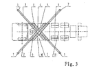
- Fig. 3 is a top view showing another embodiment of the struts in double X-form according to the present invention, in which, the sheath tubes 9, 10 are located above the sheath tubes 3, 4.
- Fig. 4 is a top view showing a further embodiment of the struts in double X-form according to the present invention, in which, the sheath tubes 3, 4 are located above the sheath tubes 9, 10. Further, the parallel sheath tubes are spaced from one another for a distance or are close to one another as actually required. Furthermore, the case where the sheath tubes 9, 10 are located above the sheath tubes 3, 4 and the parallel sheath tubes are spaced from one another for a distance is not shown in the figures, but such a manner is also within the scope of the present invention.
- Fig. 5 is a top view showing an embodiment of the struts in double X-form according to the present invention as shown in Fig. 2 , in which the extensible arms 2 are multi-grade extensible arms, and the form of multi-grade extensible arms is also applicable to the manners as shown in Figs. 3 and 4 .
- a double X-form strut according to the present invention eliminates the constraints that a swinging rearward strut cannot operate in a narrow construction site.
- the structural design is more simple, and a length along which stresses are transmitted to the rear struts is shorter, thereby reducing a weight of the vehicle frame and the cost.
- supporting points of the four protruding support parts form supporting points in a square-shape, full consideration has been taken in the design concerning the specific positions for the centre of gravity of the vehicle and the struts.
- a relatively high stability is obtained with diagonal lines intersecting substantially at the centre of gravity of the concrete pump vehicle.
Landscapes
- Engineering & Computer Science (AREA)
- Mechanical Engineering (AREA)
- Architecture (AREA)
- Civil Engineering (AREA)
- Structural Engineering (AREA)
- On-Site Construction Work That Accompanies The Preparation And Application Of Concrete (AREA)
- Road Paving Machines (AREA)
- Vehicle Cleaning, Maintenance, Repair, Refitting, And Outriggers (AREA)
Applications Claiming Priority (2)
| Application Number | Priority Date | Filing Date | Title |
|---|---|---|---|
| CNB2007101624271A CN100528647C (zh) | 2007-09-21 | 2007-09-21 | 一种行走式机械支承装置及具有这种支承装置的混凝土泵车 |
| PCT/CN2007/003630 WO2009036627A1 (fr) | 2007-09-21 | 2007-12-17 | Dispositif de support pour machines de marche |
Publications (2)
| Publication Number | Publication Date |
|---|---|
| EP2202121A1 true EP2202121A1 (de) | 2010-06-30 |
| EP2202121A4 EP2202121A4 (de) | 2013-01-16 |
Family
ID=39093700
Family Applications (1)
| Application Number | Title | Priority Date | Filing Date |
|---|---|---|---|
| EP07845958A Withdrawn EP2202121A4 (de) | 2007-09-21 | 2007-12-17 | Stützvorrichtung für fahrbare maschinen |
Country Status (4)
| Country | Link |
|---|---|
| US (1) | US8302993B2 (de) |
| EP (1) | EP2202121A4 (de) |
| CN (1) | CN100528647C (de) |
| WO (1) | WO2009036627A1 (de) |
Cited By (5)
| Publication number | Priority date | Publication date | Assignee | Title |
|---|---|---|---|---|
| CN102094531A (zh) * | 2010-12-23 | 2011-06-15 | 三一重工股份有限公司 | 工程机械及其固定转塔 |
| CN103158682A (zh) * | 2011-12-14 | 2013-06-19 | 徐工集团工程机械股份有限公司 | 一种具有x支腿的混凝土泵车底架结构及混凝土泵车 |
| WO2014029552A1 (de) * | 2012-08-24 | 2014-02-27 | Putzmeister Engineering Gmbh | Fahrbare betonpumpe |
| WO2015198089A1 (en) * | 2014-06-23 | 2015-12-30 | Socage S.R.L. | Support frame |
| EP3198105A4 (de) * | 2014-09-25 | 2018-07-11 | Andrew Niemczyk | Mobiles bohrgestell |
Families Citing this family (15)
| Publication number | Priority date | Publication date | Assignee | Title |
|---|---|---|---|---|
| CN102248933A (zh) * | 2011-05-23 | 2011-11-23 | 三一重工股份有限公司 | 泵车及其臂架安全旋转范围反馈系统、方法 |
| CN102745179A (zh) * | 2012-07-19 | 2012-10-24 | 三一重工股份有限公司 | 支腿装置和背罐车 |
| US20140260941A1 (en) * | 2013-03-14 | 2014-09-18 | United States Government, As Represented By The Secretary Of The Navy | Mountable Fixture for Absorbing Recoil |
| US10240884B1 (en) | 2013-03-14 | 2019-03-26 | The United States Of America As Represented By The Secretary Of The Navy | Mountable fixture for absorbing recoil |
| US9883848B2 (en) | 2013-09-13 | 2018-02-06 | Maui Imaging, Inc. | Ultrasound imaging using apparent point-source transmit transducer |
| CN105820103B (zh) * | 2015-01-28 | 2020-11-03 | 北京韩美药品有限公司 | N-苯甲酸基取代的苯并吡咯啉-2-酮类衍生物及其用途 |
| CN106476772A (zh) * | 2016-10-11 | 2017-03-08 | 湖南挖挖工程科技有限公司 | 一种泵车的支腿机构 |
| IT201700076727A1 (it) * | 2017-07-07 | 2019-01-07 | Manitou Italia Srl | Sistema per stabilizzare macchine operatrici semoventi. |
| DE102018110391A1 (de) * | 2018-04-30 | 2019-10-31 | Liebherr-Betonpumpen Gmbh | Autobetonpumpe und Schwenkbein für eine Autobetonpumpe |
| DE102018127828A1 (de) * | 2018-11-07 | 2020-05-07 | Liebherr-Betonpumpen Gmbh | Autobetonpumpe |
| CN112324143A (zh) * | 2020-11-14 | 2021-02-05 | 深圳市罗湖建筑安装工程有限公司 | 一种混凝土浇筑的施工设备及方法 |
| CN114212057A (zh) * | 2021-11-04 | 2022-03-22 | 湖南响箭重工科技股份有限公司 | 用于泵车的底架箱体结构 |
| CN114314459A (zh) * | 2022-01-07 | 2022-04-12 | 江苏徐工工程机械研究院有限公司 | 高空作业车副车架和高空作业车 |
| CN117227673B (zh) * | 2023-11-13 | 2024-01-23 | 山东鸿达重工机械制造有限公司 | 一种混凝土泵车的辅助支腿结构 |
| CN120270921A (zh) * | 2025-05-21 | 2025-07-08 | 徐州重型机械有限公司 | 一种双支腿形式的车架支腿结构及轮式起重机 |
Family Cites Families (14)
| Publication number | Priority date | Publication date | Assignee | Title |
|---|---|---|---|---|
| FR2134306B1 (de) * | 1971-04-26 | 1977-06-17 | Potain Sa | |
| DE3124029A1 (de) * | 1981-06-19 | 1983-03-17 | Stetter Gmbh, 8940 Memmingen | Vorrichtung zum verstellen von stuetzverlaengerungen, insbesondere an arbeitsmaschinen wie betonpumpen o.dgl. |
| DE3830315A1 (de) * | 1988-09-07 | 1990-03-08 | Putzmeister Maschf | Fahrbare betonpumpe |
| DE4203820C5 (de) * | 1992-02-10 | 2011-01-13 | Hudelmaier, Ulrike | Fahrbare Betonpumpe |
| DE29613415U1 (de) * | 1996-08-02 | 1996-09-19 | Compact Truck Ag, Zug | Kranfahrzeug |
| DE19737678C2 (de) * | 1997-08-29 | 2000-10-05 | Schwing Gmbh F | Fahrzeug mit Rahmenabstützung |
| DE10032622A1 (de) * | 2000-07-07 | 2002-01-17 | Putzmeister Ag | Stützausleger für fahrbare Arbeitsmaschinen und Autobetonpumpen mit solchen Stützauslegern |
| WO2003013999A2 (en) * | 2001-08-03 | 2003-02-20 | The Government Of The United States Of America, As Represented By The Secretary Of The Department Of Health And Human Services, Centers For Disease Control And Prevention | Mobile load handling apparatus |
| US6811161B1 (en) * | 2001-08-23 | 2004-11-02 | Sutphen Corporation | Fire engine having extension ladder and lateral stabilizers |
| US20060043718A1 (en) * | 2004-09-01 | 2006-03-02 | Mayer Martin G | Vertical outrigger leg |
| DE202005005705U1 (de) * | 2005-04-08 | 2005-08-25 | B. Teupen Maschinenbau Gmbh | Transportable Arbeitsmaschine mit einem auf einem Drehtisch montierten Auslegerarm |
| CN100497052C (zh) * | 2005-12-30 | 2009-06-10 | 三一重工股份有限公司 | 用于行走机械的可伸缩式支腿及具有该支腿的混凝土泵车 |
| CN101204950A (zh) * | 2006-12-22 | 2008-06-25 | 三一重工股份有限公司 | 行走式机械中使用的可伸缩支承装置 |
| CN201120882Y (zh) * | 2007-09-21 | 2008-09-24 | 三一重工股份有限公司 | 一种行走机械支承装置及具有这种支承装置的混凝土泵车 |
-
2007
- 2007-09-21 CN CNB2007101624271A patent/CN100528647C/zh active Active
- 2007-12-17 WO PCT/CN2007/003630 patent/WO2009036627A1/zh not_active Ceased
- 2007-12-17 US US12/679,383 patent/US8302993B2/en not_active Expired - Fee Related
- 2007-12-17 EP EP07845958A patent/EP2202121A4/de not_active Withdrawn
Cited By (6)
| Publication number | Priority date | Publication date | Assignee | Title |
|---|---|---|---|---|
| CN102094531A (zh) * | 2010-12-23 | 2011-06-15 | 三一重工股份有限公司 | 工程机械及其固定转塔 |
| CN103158682A (zh) * | 2011-12-14 | 2013-06-19 | 徐工集团工程机械股份有限公司 | 一种具有x支腿的混凝土泵车底架结构及混凝土泵车 |
| WO2014029552A1 (de) * | 2012-08-24 | 2014-02-27 | Putzmeister Engineering Gmbh | Fahrbare betonpumpe |
| US9175484B2 (en) | 2012-08-24 | 2015-11-03 | Putzmeister Engineering Gmbh | Mobile concrete pump |
| WO2015198089A1 (en) * | 2014-06-23 | 2015-12-30 | Socage S.R.L. | Support frame |
| EP3198105A4 (de) * | 2014-09-25 | 2018-07-11 | Andrew Niemczyk | Mobiles bohrgestell |
Also Published As
| Publication number | Publication date |
|---|---|
| CN101125544A (zh) | 2008-02-20 |
| US20110001309A1 (en) | 2011-01-06 |
| WO2009036627A1 (fr) | 2009-03-26 |
| EP2202121A4 (de) | 2013-01-16 |
| US8302993B2 (en) | 2012-11-06 |
| CN100528647C (zh) | 2009-08-19 |
Similar Documents
| Publication | Publication Date | Title |
|---|---|---|
| US8302993B2 (en) | Support device for walking machines | |
| ES2335629B1 (es) | "dispositivo de soporte telescopico de vehiculo movil". | |
| US20160362149A1 (en) | Construction Vehicle Having a Tippable Chassis | |
| US20090167008A1 (en) | Travel unit for mobile machines | |
| JP2008529886A (ja) | 走行可能な作業機用のアウトリガー | |
| CN110090379B (zh) | 臂架组件和消防车 | |
| JP7309760B2 (ja) | 主ブームと主ブーム張出しとの間に可動アダプタを備える車両クレーン | |
| CN110467115A (zh) | 叉吊轮式起重机 | |
| US4555031A (en) | Vehicular crane of high carrying capacity having an extensible arm | |
| CN102364010B (zh) | 一种轮式布料机械 | |
| JP5869242B2 (ja) | 高所作業車 | |
| JP7543126B2 (ja) | 車両クレーン | |
| SE459307B (sv) | Kranfoersedd skogsmaskin | |
| RU118626U1 (ru) | Опорный контур грузоподъемной машины | |
| CN206872373U (zh) | 一种轮式隧道拱架作业车 | |
| CN109554995A (zh) | 一种可以调节工作尺寸的公路铺设用路面抹平装置 | |
| CN109458218B (zh) | 直臂式重载隧道多功能作业平台 | |
| JPH02232467A (ja) | ブーム装置付コンクリートポンプ車 | |
| CN208585299U (zh) | 儿童推车 | |
| CN214879616U (zh) | 一种便于转场的折叠起重机 | |
| CN201120882Y (zh) | 一种行走机械支承装置及具有这种支承装置的混凝土泵车 | |
| JPS585337B2 (ja) | グラブバケツト装置を備えた移動式堀削機 | |
| CN210363751U (zh) | 一种工程机械快速辅助支撑装置 | |
| CN202573937U (zh) | 混凝土泵送设备及其车架 | |
| CN102491202B (zh) | 行车式起重机 |
Legal Events
| Date | Code | Title | Description |
|---|---|---|---|
| PUAI | Public reference made under article 153(3) epc to a published international application that has entered the european phase |
Free format text: ORIGINAL CODE: 0009012 |
|
| 17P | Request for examination filed |
Effective date: 20100421 |
|
| AK | Designated contracting states |
Kind code of ref document: A1 Designated state(s): AT BE BG CH CY CZ DE DK EE ES FI FR GB GR HU IE IS IT LI LT LU LV MC MT NL PL PT RO SE SI SK TR |
|
| AX | Request for extension of the european patent |
Extension state: AL BA HR MK RS |
|
| DAX | Request for extension of the european patent (deleted) | ||
| A4 | Supplementary search report drawn up and despatched |
Effective date: 20121214 |
|
| RIC1 | Information provided on ipc code assigned before grant |
Ipc: B60P 3/16 20060101ALI20121210BHEP Ipc: E04G 21/04 20060101ALI20121210BHEP Ipc: F16M 11/26 20060101ALI20121210BHEP Ipc: B60S 9/12 20060101AFI20121210BHEP Ipc: B66C 23/78 20060101ALI20121210BHEP |
|
| STAA | Information on the status of an ep patent application or granted ep patent |
Free format text: STATUS: THE APPLICATION IS DEEMED TO BE WITHDRAWN |
|
| 18D | Application deemed to be withdrawn |
Effective date: 20130713 |