EP2202122A1 - Schienenfahrzeugbremszylinder - Google Patents
Schienenfahrzeugbremszylinder Download PDFInfo
- Publication number
- EP2202122A1 EP2202122A1 EP20090179518 EP09179518A EP2202122A1 EP 2202122 A1 EP2202122 A1 EP 2202122A1 EP 20090179518 EP20090179518 EP 20090179518 EP 09179518 A EP09179518 A EP 09179518A EP 2202122 A1 EP2202122 A1 EP 2202122A1
- Authority
- EP
- European Patent Office
- Prior art keywords
- orifice
- distributor
- brake cylinder
- actuating member
- occupies
- Prior art date
- Legal status (The legal status is an assumption and is not a legal conclusion. Google has not performed a legal analysis and makes no representation as to the accuracy of the status listed.)
- Granted
Links
Images


Classifications
-
- B—PERFORMING OPERATIONS; TRANSPORTING
- B60—VEHICLES IN GENERAL
- B60T—VEHICLE BRAKE CONTROL SYSTEMS OR PARTS THEREOF; BRAKE CONTROL SYSTEMS OR PARTS THEREOF, IN GENERAL; ARRANGEMENT OF BRAKING ELEMENTS ON VEHICLES IN GENERAL; PORTABLE DEVICES FOR PREVENTING UNWANTED MOVEMENT OF VEHICLES; VEHICLE MODIFICATIONS TO FACILITATE COOLING OF BRAKES
- B60T17/00—Component parts, details, or accessories of power brake systems not covered by groups B60T8/00, B60T13/00 or B60T15/00, or presenting other characteristic features
- B60T17/08—Brake cylinders other than ultimate actuators
-
- B—PERFORMING OPERATIONS; TRANSPORTING
- B60—VEHICLES IN GENERAL
- B60T—VEHICLE BRAKE CONTROL SYSTEMS OR PARTS THEREOF; BRAKE CONTROL SYSTEMS OR PARTS THEREOF, IN GENERAL; ARRANGEMENT OF BRAKING ELEMENTS ON VEHICLES IN GENERAL; PORTABLE DEVICES FOR PREVENTING UNWANTED MOVEMENT OF VEHICLES; VEHICLE MODIFICATIONS TO FACILITATE COOLING OF BRAKES
- B60T15/00—Construction arrangement, or operation of valves incorporated in power brake systems and not covered by groups B60T11/00 or B60T13/00
- B60T15/02—Application and release valves
- B60T15/021—Railway control or brake valves
-
- Y—GENERAL TAGGING OF NEW TECHNOLOGICAL DEVELOPMENTS; GENERAL TAGGING OF CROSS-SECTIONAL TECHNOLOGIES SPANNING OVER SEVERAL SECTIONS OF THE IPC; TECHNICAL SUBJECTS COVERED BY FORMER USPC CROSS-REFERENCE ART COLLECTIONS [XRACs] AND DIGESTS
- Y10—TECHNICAL SUBJECTS COVERED BY FORMER USPC
- Y10T—TECHNICAL SUBJECTS COVERED BY FORMER US CLASSIFICATION
- Y10T137/00—Fluid handling
- Y10T137/8593—Systems
- Y10T137/86493—Multi-way valve unit
- Y10T137/86574—Supply and exhaust
- Y10T137/8667—Reciprocating valve
- Y10T137/86694—Piston valve
- Y10T137/86702—With internal flow passage
-
- Y—GENERAL TAGGING OF NEW TECHNOLOGICAL DEVELOPMENTS; GENERAL TAGGING OF CROSS-SECTIONAL TECHNOLOGIES SPANNING OVER SEVERAL SECTIONS OF THE IPC; TECHNICAL SUBJECTS COVERED BY FORMER USPC CROSS-REFERENCE ART COLLECTIONS [XRACs] AND DIGESTS
- Y10—TECHNICAL SUBJECTS COVERED BY FORMER USPC
- Y10T—TECHNICAL SUBJECTS COVERED BY FORMER US CLASSIFICATION
- Y10T137/00—Fluid handling
- Y10T137/8593—Systems
- Y10T137/86493—Multi-way valve unit
- Y10T137/86574—Supply and exhaust
- Y10T137/8667—Reciprocating valve
- Y10T137/86694—Piston valve
- Y10T137/8671—With annular passage [e.g., spool]
Definitions
- the invention relates to the field of braking of railway vehicles.
- a brake cylinder controlled by a pneumatic pressure agent and adapted to act on a wheelhouse in order to actuate a braking device, comprising, for example, one or more friction pads adapted to grip a brake disc connected to the wheels. of the vehicle or directly a wheel of the vehicle.
- Such a brake cylinder generally comprises a body and a piston movable relative to the body to act on a brake linkage and defining with said body a pressure chamber adapted to be fed by a source of pneumatic pressure agent.
- Some brake cylinders further comprise a manual braking device comprising an auxiliary actuating member movable relative to said body and said piston.
- This member in the absence of external constraints, occupies a rest position in which it is away from the piston so that it exerts no effort on it.
- an operator comes to actuate this body, for example using a lever multiplier, to make him occupy a thrust position in which it is in contact with the piston and exerts a mechanical force on it.
- the invention aims to improve the brake cylinders comprising such a manual braking device.
- the selective linking means mechanically linked to the auxiliary actuating member change their position so as to put in fluid communication the first and the second orifice of the cylinder.
- the pressure chamber is thus in fluid communication with the atmosphere, which causes the leakage of the pressure agent and the removal of the pneumatic force exerted on the piston.
- the non-superposition of the pneumatic and manual braking provided by the cylinder according to the invention makes it possible to avoid over-sizing of the piston and the wheelhouse as was practiced in conventional brake cylinders with a manual braking device.
- the Figures 1 and 2 represent a brake cylinder 1 which, in the present example, is adapted to actuate a linkage 2 rail brake.
- This assembly makes it possible to act on a brake disc 3 mounted for example on a axle 4 of the railway vehicle, or directly on the wheel to brake.
- the brake disc 3 is here seen in profile and only its upper half has been shown.
- the wheelhouse 2 conventionally comprises two braking pads 5 arranged on either side of the brake disc 3 and which, in the absence of bias, are away from the brake disc 3 (see FIG. figure 1 ) and which, during a braking action, are urged by the wheelhouse 2 against the brake disc 3 (see figure 2 ) to slow down and / or stop the brake disc 3 by friction.
- the wheelhouse 2 comprises for this purpose two rigid levers 6 each comprising an upper arm 6A and a lower arm 6B integral, each lever 6 being rotatably mounted about an axis 7 integral with the chassis of the railway vehicle.
- the lower arm 6B of each lever 6 is connected to one of the braking pads 5.
- the upper arm 6A of each lever 6 is connected to a hinge 8.
- the brake cylinder 1 is attached by two of its ends to the hinges 8 and is adapted to print at the joints 8 such a movement toward or away from.
- the brake cylinder 1 is connected via a conduit 9 to a source of pneumatic pressure medium such as, for example, compressed air.
- the brake cylinder 1 comprises in particular a body 11, a piston 13 and a sliding joint 12 adapted to scrape the edges of the body 11, so as to define a pressure chamber 10.
- the piston 13 is itself attached to a part corner 14 having a triangular section.
- the wedge piece 14 cooperates with a first rolling stopper 15 connected to the body 11 and with a second rolling stopper 16 connected to a push rod 17.
- the push rod 17 is formed of a device commonly called “adjuster” and allowing direct transmission of the displacements of the thrust bearing 16 to the corresponding articulation 8 while catching the clearances between the second thrust bearing and the piece of corner 14.
- the adjusters are conventional devices that will not be further described in detail right here. It suffices to mention here that the push rod 17 is adapted to transmit to the corresponding articulation 8 the forces exerted on the second rolling stopper 16.
- a spring 18 is furthermore disposed between the body 11 and the push rod 17 and serves to urge the second rolling stopper 16 against the corner piece 14.
- the brake cylinder 1 is thus mounted between the two joints 8, the body 11 being integral with one of these joints 8 and the end of the push rod 17 being integral with the other articulation 8.
- the piston 13 and the wedge piece 14 are movable in a first direction 19 which corresponds to the vertical on the Figures 1 and 2 .
- the push rod 17 is movable in a second direction 20, perpendicular to the first direction 19 and which corresponds to the horizontal on the Figures 1 and 2 .
- the brake cylinder 1 is shown in the waiting position. In this position, the fluid pressure is not exerted, that is to say that the conduit 9 is put at atmospheric pressure.
- the spring 18 which urges the second rolling stopper 16 towards the first rolling stopper 15, causes the rise of the wedge piece 14 and the piston 13, so that the pressure chamber 10 has a minimum volume.
- the brake cylinder 1 is shown in the braking position.
- the duct 9 receives the pressure agent which fills the chamber 10 and urges the piston 13 and the wedge piece 14 downwards, which has the effect of moving the stops 15, 16 and therefore the joints 8.
- the volume of the pressure chamber 10 is maximum in this position.
- the brake cylinder 1 'thus comprises a body 11' forming a casing in which are mounted the various elements of the brake cylinder 1 ', in particular a piston 13' movable in a first direction 19 'and fixed to a corner piece 14' adapted to cooperate in depression between a first bearing stop 15 'and a second bearing stop 16'.
- the first bearing stop 15 ' is mounted on the body 11' and the second bearing 16 'is mounted at the end of a push rod 17', movable in a second direction 20 ', the other end 22 'is intended to be connected to one of the joints 8 of the diagrams of Figures 1 and 2 the other articulation 8 being fixed on the body 11 '.
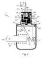
- a spring 18 ' urges the push rod 17' so that the second rolling stopper 16 'approaches the first rolling stopper 15', that is to say towards the waiting position of the brake cylinder 1 (which is the one represented in the figure 3 ).
- the body 11 ' has a circular opening 25' facing the piston 13 'and slidably receiving an auxiliary actuating member 26' fitting into the opening 25 'in a sealed manner by virtue of a non-compliant O-ring. represent.
- the auxiliary actuating member 26 ' is urged permanently away from the piston 13' by elastic relief means, here formed by a spring 27 '.
- the auxiliary actuating member 26 ' comprises three internal ducts 40', 50 'and 60'.
- the duct 40 ' has an external orifice 41' of entry in fluid communication with a source not shown of pneumatic pressure agent (here compressed air but alternatively other types of gas can be used) and an orifice internal 42 'leading to a slider 28' movably mounted in the actuating member 26 'between a projecting position ( figures 3 and 4 ) vis-à-vis the lower end of the member 26 '(that facing the piston 13') and a retracted position ( figure 5 ) in which the slide 28 'is flush with the same end.
- a source not shown of pneumatic pressure agent here compressed air but alternatively other types of gas can be used
- the conduit 50 ' which is opposite the conduit 40' has an external orifice 51 'output in fluid communication with the atmosphere and an inner orifice 52' opening on the slider 28 '.
- the duct 60 'located near the lower end of the thrust member 26' has an external orifice 61 'of entry in fluid communication with the pressure chamber 10' and an internal orifice 62 'opening on the slide 28.
- the slider 28 ' also comprises a pipe 70' in three portions.
- the first upper portion 70'A extends transversely to the slide 28 'along its entire width so as to have two opposite orifices 71' and 72 '.
- the second lower portion 70'B also extends transversely to the slider about half of its width and has an orifice 73 '.
- the third connecting portion 70'C extends in the axis of the slider 28 'and connects the two portions 70'A and 70'B.
- the slider 28 ' is permanently biased towards its projecting position by a spring 29' disposed between the slider 28 'and the auxiliary actuating member 26'.
- the pressure chamber 10 ' has been drained and is at atmospheric pressure while the auxiliary actuating member 26' is in the rest position and the slider 28 'is in its stable position of isolation.
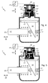
- the spring 18 'urges the push rod 17' so that the second rolling stopper 16 'approaches the first rolling stopper 15', so that the corner piece 14 'rises bringing with it the piston 13' which is then in the high position.
- the pressure chamber 10 ' fills with compressed air, the pressure increasing with the introduction of the fluid so that it causes the displacement of the piston 13' and thus the braking of the wheel.
- the isolation of the chamber 10 'with respect to the source of pressure medium makes it possible to limit the emptying to the volume of compressed air contained in the chamber 10' (at the moment of the change of position of the slider 28 ') and therefore of avoid any loss of pneumatic pressure agent in the supply circuit.
- FIG 6 schematically illustrates a variant of the first embodiment for which the same reference numerals have been used but with a "instead of".
- the body 11 ", the piston 13" and the unrepresented elements of the cylinder 1 " are identical to those described above.
- the cylinder 1 does not comprise a slider mounted to move in the auxiliary actuating member 26", the means for selective connection between orifices here being constituted by a distributor 80 "distinct from the member 26".
- the distributor 80 is of the two-position monostable type (thanks to the presence of a spring 29") and three ports 41 ", 51" and 73 “respectively connected to a source of pneumatic pressure agent, at the atmosphere and to the room 10 ".
- the distributor 80" moves to the link position. Now in fluid communication with the atmosphere and isolated from the source of pneumatic pressure medium, the chamber 10 "is drained very quickly.
- the isolation of the chamber 10" with respect to the source of pressure medium makes it possible to limit the emptying to the volume of compressed air contained in the chamber 10 "(at the time of the change of position of the distributor 80") and thus to avoid any loss of compressed air in the supply circuit.
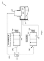
- the figure 7 schematically illustrates a second embodiment of a brake cylinder according to the invention, for which the same numerical references were used as for the first embodiment but increased by 100.
- the body 111 ', the piston 113' and the non-illustrated elements of the cylinder 101 ' are identical to the first embodiment.
- the means for selective connection between orifices here consist of a distributor 180 'of monostable type with two positions (thanks to the presence of a spring 129'), but having only two external orifices 151 'and 173' respectively connected to the atmosphere and the pressure chamber 110 '.
- the pressure chamber 110 ' is permanently connected to the source of pneumatic pressure agent. The latter thus fully empties when the distributor 180 'goes into its connecting position under the effect of a force exerted by the multiplier lever 131'.
- the distributor 180' When an operator acts on the multiplier lever 131 ', the distributor 180' goes into the connecting position. Now in fluid communication with the atmosphere, the chamber 110 'and the compressed air supply circuit drain very quickly. In parallel with the change of position of the distributor 180 ', the auxiliary actuating member 126' pushes against the piston 113 ', thereby applying to this piston 113' a manual braking force which replaces the braking force exerted previously by the compressed air contained in the chamber 110 '.
- the selective connection means may comprise instead of the distributor 180 ', a slider mounted in the auxiliary actuating member 126' in a manner similar to the first embodiment of the invention. realization illustrated by the Figures 3 to 5 .
- the figure 8 schematically illustrates a third embodiment of a brake cylinder according to the invention, for which the same numerical references were used as for the first embodiment but increased by 200.
- the body 211 ', the piston 213' and the non-illustrated elements of the cylinder 201 ' are identical to the previous embodiments.
- the cylinder 201 ' comprises two distributors 280' and 290 'of monostable type with two positions due to the presence of a spring 229', respectively 291 '.
- the distributor 280 ' has two external orifices 251' and 273 'in fluid communication, respectively with the atmosphere and with the pressure chamber 210'.
- This distributor 280 ' is adapted to occupy a first stable insulation position in which the orifices 251' and 273 'are isolated from each other and second connection position in which the orifices 251' and 273 'are in communication fluid.
- the distributor 290 has two external orifices 292' and 293 'respectively connected to the pressure chamber 210' and to a source of pneumatic pressure agent.
- This distributor 290 ' is adapted to occupy a first stable connection position in which the orifices 292' and 293 'are in fluid communication and a second isolation position in which the orifices 292' and 293 'are isolated from one another. 'other.
- the distributor 280' goes into the link position while the distributor 290 'goes into the isolated position. Now in fluid communication with the atmosphere and isolated from the source of pneumatic pressure agent, the chamber 210 'is drained very quickly. As explained above, the isolation of the chamber 210 'with respect to the source of pressure agent makes it possible to limit the emptying to the volume of compressed air contained in the chamber 210' (at the moment of the change of position of the dispenser 280 ' ) and thus avoid any loss of compressed air in the supply circuit.
- this embodiment provides exactly the same functions as the first embodiment, that of emptying the pressure chamber 210 'being performed by the distributor 280' and that isolating this same pressure chamber 210 'vis-à-vis the source of pneumatic pressure agent being performed by the distributor 290'.
- the lever is replaced by a winch or a crank.
Landscapes
- Engineering & Computer Science (AREA)
- Transportation (AREA)
- Mechanical Engineering (AREA)
- Braking Arrangements (AREA)
- Braking Systems And Boosters (AREA)
Applications Claiming Priority (1)
| Application Number | Priority Date | Filing Date | Title |
|---|---|---|---|
| FR0859061A FR2940223B1 (fr) | 2008-12-24 | 2008-12-24 | Cylindre de frein ferroviaire |
Publications (2)
| Publication Number | Publication Date |
|---|---|
| EP2202122A1 true EP2202122A1 (de) | 2010-06-30 |
| EP2202122B1 EP2202122B1 (de) | 2012-11-14 |
Family
ID=40929543
Family Applications (1)
| Application Number | Title | Priority Date | Filing Date |
|---|---|---|---|
| EP20090179518 Active EP2202122B1 (de) | 2008-12-24 | 2009-12-16 | Schienenfahrzeugbremszylinder |
Country Status (4)
| Country | Link |
|---|---|
| US (1) | US8251189B2 (de) |
| EP (1) | EP2202122B1 (de) |
| CN (1) | CN101758833B (de) |
| FR (1) | FR2940223B1 (de) |
Cited By (4)
| Publication number | Priority date | Publication date | Assignee | Title |
|---|---|---|---|---|
| FR3027270A1 (fr) * | 2014-10-15 | 2016-04-22 | Faiveley Transp Amiens | Systeme de freinage ferroviaire pour vehicule ferroviaire et procede de freinage d'un vehicule ferroviaire comportant un tel systeme |
| FR3048399A1 (fr) * | 2016-03-04 | 2017-09-08 | Faiveley Transp Amiens | Systeme de freinage ferroviaire pour vehicule ferroviaire et procede de freinage d'un vehicule ferroviaire comportant un tel systeme |
| FR3048400A1 (fr) * | 2016-03-04 | 2017-09-08 | Faiveley Transp Amiens | Systeme de freinage ferroviaire pour vehicule ferroviaire et procede de freinage d'un vehicule ferroviaire comportant un tel systeme |
| US20180222497A1 (en) * | 2014-12-16 | 2018-08-09 | Faiveley Transport Amiens | Rail vehicle braking system and braking method for a rail vehicle comprising such a system |
Families Citing this family (3)
| Publication number | Priority date | Publication date | Assignee | Title |
|---|---|---|---|---|
| US10295439B2 (en) * | 2014-05-21 | 2019-05-21 | Eaton Intelligent Power Limited | Enclosure diagnostic and control systems |
| FR3049027B1 (fr) * | 2016-03-21 | 2018-04-13 | Faiveley Transport Amiens | Systeme de freinage ferroviaire pour vehicule ferroviaire |
| ES2927722T3 (es) * | 2019-02-15 | 2022-11-10 | Knorr Bremse Systeme Fuer Nutzfahrzeuge Gmbh | Unidad de control neumático |
Citations (4)
| Publication number | Priority date | Publication date | Assignee | Title |
|---|---|---|---|---|
| GB264197A (en) * | 1925-08-13 | 1927-01-13 | Ivar Drolshammer | Improvements in or relating to compressed-air brakes |
| GB865155A (en) * | 1957-06-26 | 1961-04-12 | Matisa Materiel Ind Sa | Improvements in and relating to ballast-tamping or track-packing machines |
| US5429426A (en) * | 1994-03-31 | 1995-07-04 | Westinghouse Air Brake Company | Brake cylinder pressure relay valve for railroad freight car |
| FR2716856A1 (fr) * | 1994-03-04 | 1995-09-08 | Knorr Bremse Systeme Schienenf | Etrier de frein à mâchoires pour freins à disque de véhicules sur rails . |
Family Cites Families (5)
| Publication number | Priority date | Publication date | Assignee | Title |
|---|---|---|---|---|
| US253139A (en) * | 1882-01-31 | wenger | ||
| US1877700A (en) * | 1931-06-25 | 1932-09-13 | Silvene Anthony | Air brake |
| US2675099A (en) * | 1950-10-24 | 1954-04-13 | Troy Leonard | Fluid pressure vehicle braking system |
| US3234968A (en) * | 1962-12-21 | 1966-02-15 | White Sales Corp Graham | Master and slave valve assembly |
| US7156471B2 (en) * | 2004-10-28 | 2007-01-02 | Wabtec Holding Corp. | Two-stage cylinder for applying automatic set and release hand brake |
-
2008
- 2008-12-24 FR FR0859061A patent/FR2940223B1/fr not_active Expired - Fee Related
-
2009
- 2009-12-16 EP EP20090179518 patent/EP2202122B1/de active Active
- 2009-12-24 CN CN200910266360.5A patent/CN101758833B/zh active Active
- 2009-12-24 US US12/647,109 patent/US8251189B2/en active Active
Patent Citations (4)
| Publication number | Priority date | Publication date | Assignee | Title |
|---|---|---|---|---|
| GB264197A (en) * | 1925-08-13 | 1927-01-13 | Ivar Drolshammer | Improvements in or relating to compressed-air brakes |
| GB865155A (en) * | 1957-06-26 | 1961-04-12 | Matisa Materiel Ind Sa | Improvements in and relating to ballast-tamping or track-packing machines |
| FR2716856A1 (fr) * | 1994-03-04 | 1995-09-08 | Knorr Bremse Systeme Schienenf | Etrier de frein à mâchoires pour freins à disque de véhicules sur rails . |
| US5429426A (en) * | 1994-03-31 | 1995-07-04 | Westinghouse Air Brake Company | Brake cylinder pressure relay valve for railroad freight car |
Cited By (10)
| Publication number | Priority date | Publication date | Assignee | Title |
|---|---|---|---|---|
| FR3027270A1 (fr) * | 2014-10-15 | 2016-04-22 | Faiveley Transp Amiens | Systeme de freinage ferroviaire pour vehicule ferroviaire et procede de freinage d'un vehicule ferroviaire comportant un tel systeme |
| US20180222497A1 (en) * | 2014-12-16 | 2018-08-09 | Faiveley Transport Amiens | Rail vehicle braking system and braking method for a rail vehicle comprising such a system |
| US10501099B2 (en) * | 2014-12-16 | 2019-12-10 | Faiveley Transport Amiens | Rail vehicle braking system and braking method for a rail vehicle comprising such a system |
| FR3048399A1 (fr) * | 2016-03-04 | 2017-09-08 | Faiveley Transp Amiens | Systeme de freinage ferroviaire pour vehicule ferroviaire et procede de freinage d'un vehicule ferroviaire comportant un tel systeme |
| FR3048400A1 (fr) * | 2016-03-04 | 2017-09-08 | Faiveley Transp Amiens | Systeme de freinage ferroviaire pour vehicule ferroviaire et procede de freinage d'un vehicule ferroviaire comportant un tel systeme |
| WO2017149245A1 (fr) * | 2016-03-04 | 2017-09-08 | Faiveley Transport Amiens | Système de freinage ferroviaire pour véhicule ferroviaire et procédé de freinage d'un véhicule ferroviaire comportant un tel système |
| WO2017149244A1 (fr) * | 2016-03-04 | 2017-09-08 | Faiveley Transport Amiens | Système de freinage ferroviaire pour véhicule ferroviaire et procédé de freinage d'un véhicule ferroviaire comportant un tel système |
| US10780873B2 (en) | 2016-03-04 | 2020-09-22 | Faiveley Transport Amiens | Rail vehicle braking system and braking method for a rail vehicle comprising such a system |
| RU2735736C2 (ru) * | 2016-03-04 | 2020-11-06 | Фейвели Транспор Амьен | Железнодорожная тормозная система для железнодорожного транспортного средства и способ торможения железнодорожного транспортного средства, содержащего такую систему |
| US10850720B2 (en) | 2016-03-04 | 2020-12-01 | Faiveley Transport Amiens | Vehicle braking system and braking method |
Also Published As
| Publication number | Publication date |
|---|---|
| FR2940223B1 (fr) | 2011-02-11 |
| CN101758833B (zh) | 2014-02-12 |
| CN101758833A (zh) | 2010-06-30 |
| US8251189B2 (en) | 2012-08-28 |
| EP2202122B1 (de) | 2012-11-14 |
| US20100155185A1 (en) | 2010-06-24 |
| FR2940223A1 (fr) | 2010-06-25 |
Similar Documents
| Publication | Publication Date | Title |
|---|---|---|
| EP2202122B1 (de) | Schienenfahrzeugbremszylinder | |
| EP2826684B1 (de) | Schienenbremssystem und Bremsverfahren eines Schienenfahrzeugs, das ein solches System umfasst | |
| EP2154391B1 (de) | Brake cylinder comprising a pressure chamber | |
| EP0161119B1 (de) | Scheibenbremsbedienungsvorrichtung | |
| FR2480692A1 (fr) | Dispositif de commande pour le mecanisme a soupape d'un servofrein | |
| FR2545055A1 (fr) | Amplificateur de force hydraulique, notamment pour systeme de freinage de vehicule automobile | |
| FR2751602A1 (fr) | Dispositif de freinage assiste a rapport d'assistance variable | |
| EP2826683A1 (de) | Schienenbremssystem für Schienenfahrzeug, und Bremsverfahren eines Schienenfahrzeugs, das ein solches System umfasst | |
| EP0467725B1 (de) | Hydraulikantrieb mit Nachstellvorrichtung | |
| EP2085277B1 (de) | Bremskraftverstärker zur Schnellauslösung der Bremse | |
| EP1457400A1 (de) | Bremskraftvorrichtung mit verbesserter Bremsempfindlichkeit | |
| WO2019011504A1 (fr) | Système de freinage électronique découplé avec un dispositif de transmission de mouvement à compensation des effets radiaux | |
| FR2509805A1 (fr) | Amplificateur de force hydraulique | |
| WO1999062749A1 (fr) | Servomoteur pneumatique a disque de reaction flottant et a reaction dynamiquement annulable | |
| FR3027270A1 (fr) | Systeme de freinage ferroviaire pour vehicule ferroviaire et procede de freinage d'un vehicule ferroviaire comportant un tel systeme | |
| FR2838695A1 (fr) | Dispositif de commande de freinage a commande electrique adapte au freinage d'urgence | |
| EP0939715B1 (de) | Hilfskraftunterstütztes bremssystem mit verbesserter hydraulischer reaktion | |
| CA2875269A1 (fr) | Systeme de freinage ferroviaire et procede de freinage d'un vehicule ferroviaire comportant un tel systeme | |
| EP1409315A1 (de) | Unterdruckbremskraftverstärker mit ausdehnbarer einwegkupplung | |
| EP2085278A1 (de) | Hauptbremszylinder für einen pneumatischen Bremskraftverstärker | |
| WO2025141271A1 (fr) | Système de freinage ferroviaire pour véhicule ferroviaire à freins à au moins une garniture ou à au moins une semelle | |
| EP0687229A1 (de) | Hilfskraftbremsvorrichtung mit vereinfachter automatischer steuerung | |
| FR2480690A1 (fr) | Servofrein hydraulique | |
| EP0054469A1 (de) | Trommelbremse mit Bremskraftregelung | |
| EP0595670B1 (de) | Hydraulische Befehlseinrichtung für Bremssysteme von Kraftfahrzeugen mit zwei hydraulischen Bremskreisen |
Legal Events
| Date | Code | Title | Description |
|---|---|---|---|
| PUAI | Public reference made under article 153(3) epc to a published international application that has entered the european phase |
Free format text: ORIGINAL CODE: 0009012 |
|
| AK | Designated contracting states |
Kind code of ref document: A1 Designated state(s): AT BE BG CH CY CZ DE DK EE ES FI FR GB GR HR HU IE IS IT LI LT LU LV MC MK MT NL NO PL PT RO SE SI SK SM TR |
|
| AX | Request for extension of the european patent |
Extension state: AL BA RS |
|
| 17P | Request for examination filed |
Effective date: 20101221 |
|
| GRAP | Despatch of communication of intention to grant a patent |
Free format text: ORIGINAL CODE: EPIDOSNIGR1 |
|
| RIN1 | Information on inventor provided before grant (corrected) |
Inventor name: GONCALVES, CLAUDINO |
|
| GRAS | Grant fee paid |
Free format text: ORIGINAL CODE: EPIDOSNIGR3 |
|
| GRAA | (expected) grant |
Free format text: ORIGINAL CODE: 0009210 |
|
| AK | Designated contracting states |
Kind code of ref document: B1 Designated state(s): AT BE BG CH CY CZ DE DK EE ES FI FR GB GR HR HU IE IS IT LI LT LU LV MC MK MT NL NO PL PT RO SE SI SK SM TR |
|
| REG | Reference to a national code |
Ref country code: GB Ref legal event code: FG4D Free format text: NOT ENGLISH |
|
| REG | Reference to a national code |
Ref country code: AT Ref legal event code: REF Ref document number: 583806 Country of ref document: AT Kind code of ref document: T Effective date: 20121115 Ref country code: CH Ref legal event code: EP |
|
| REG | Reference to a national code |
Ref country code: IE Ref legal event code: FG4D Free format text: LANGUAGE OF EP DOCUMENT: FRENCH |
|
| REG | Reference to a national code |
Ref country code: DE Ref legal event code: R096 Ref document number: 602009011157 Country of ref document: DE Effective date: 20130110 |
|
| REG | Reference to a national code |
Ref country code: SE Ref legal event code: TRGR |
|
| REG | Reference to a national code |
Ref country code: NL Ref legal event code: VDEP Effective date: 20121114 |
|
| REG | Reference to a national code |
Ref country code: AT Ref legal event code: MK05 Ref document number: 583806 Country of ref document: AT Kind code of ref document: T Effective date: 20121114 |
|
| REG | Reference to a national code |
Ref country code: LT Ref legal event code: MG4D |
|
| PG25 | Lapsed in a contracting state [announced via postgrant information from national office to epo] |
Ref country code: FI Free format text: LAPSE BECAUSE OF FAILURE TO SUBMIT A TRANSLATION OF THE DESCRIPTION OR TO PAY THE FEE WITHIN THE PRESCRIBED TIME-LIMIT Effective date: 20121114 Ref country code: NO Free format text: LAPSE BECAUSE OF FAILURE TO SUBMIT A TRANSLATION OF THE DESCRIPTION OR TO PAY THE FEE WITHIN THE PRESCRIBED TIME-LIMIT Effective date: 20130214 Ref country code: ES Free format text: LAPSE BECAUSE OF FAILURE TO SUBMIT A TRANSLATION OF THE DESCRIPTION OR TO PAY THE FEE WITHIN THE PRESCRIBED TIME-LIMIT Effective date: 20130225 Ref country code: LT Free format text: LAPSE BECAUSE OF FAILURE TO SUBMIT A TRANSLATION OF THE DESCRIPTION OR TO PAY THE FEE WITHIN THE PRESCRIBED TIME-LIMIT Effective date: 20121114 Ref country code: HR Free format text: LAPSE BECAUSE OF FAILURE TO SUBMIT A TRANSLATION OF THE DESCRIPTION OR TO PAY THE FEE WITHIN THE PRESCRIBED TIME-LIMIT Effective date: 20121114 |
|
| PG25 | Lapsed in a contracting state [announced via postgrant information from national office to epo] |
Ref country code: LV Free format text: LAPSE BECAUSE OF FAILURE TO SUBMIT A TRANSLATION OF THE DESCRIPTION OR TO PAY THE FEE WITHIN THE PRESCRIBED TIME-LIMIT Effective date: 20121114 Ref country code: PT Free format text: LAPSE BECAUSE OF FAILURE TO SUBMIT A TRANSLATION OF THE DESCRIPTION OR TO PAY THE FEE WITHIN THE PRESCRIBED TIME-LIMIT Effective date: 20130314 Ref country code: PL Free format text: LAPSE BECAUSE OF FAILURE TO SUBMIT A TRANSLATION OF THE DESCRIPTION OR TO PAY THE FEE WITHIN THE PRESCRIBED TIME-LIMIT Effective date: 20121114 Ref country code: GR Free format text: LAPSE BECAUSE OF FAILURE TO SUBMIT A TRANSLATION OF THE DESCRIPTION OR TO PAY THE FEE WITHIN THE PRESCRIBED TIME-LIMIT Effective date: 20130215 Ref country code: SI Free format text: LAPSE BECAUSE OF FAILURE TO SUBMIT A TRANSLATION OF THE DESCRIPTION OR TO PAY THE FEE WITHIN THE PRESCRIBED TIME-LIMIT Effective date: 20121114 |
|
| PG25 | Lapsed in a contracting state [announced via postgrant information from national office to epo] |
Ref country code: AT Free format text: LAPSE BECAUSE OF FAILURE TO SUBMIT A TRANSLATION OF THE DESCRIPTION OR TO PAY THE FEE WITHIN THE PRESCRIBED TIME-LIMIT Effective date: 20121114 |
|
| PG25 | Lapsed in a contracting state [announced via postgrant information from national office to epo] |
Ref country code: MC Free format text: LAPSE BECAUSE OF NON-PAYMENT OF DUE FEES Effective date: 20121231 Ref country code: SK Free format text: LAPSE BECAUSE OF FAILURE TO SUBMIT A TRANSLATION OF THE DESCRIPTION OR TO PAY THE FEE WITHIN THE PRESCRIBED TIME-LIMIT Effective date: 20121114 Ref country code: CZ Free format text: LAPSE BECAUSE OF FAILURE TO SUBMIT A TRANSLATION OF THE DESCRIPTION OR TO PAY THE FEE WITHIN THE PRESCRIBED TIME-LIMIT Effective date: 20121114 Ref country code: BG Free format text: LAPSE BECAUSE OF FAILURE TO SUBMIT A TRANSLATION OF THE DESCRIPTION OR TO PAY THE FEE WITHIN THE PRESCRIBED TIME-LIMIT Effective date: 20130214 Ref country code: EE Free format text: LAPSE BECAUSE OF FAILURE TO SUBMIT A TRANSLATION OF THE DESCRIPTION OR TO PAY THE FEE WITHIN THE PRESCRIBED TIME-LIMIT Effective date: 20121114 Ref country code: DK Free format text: LAPSE BECAUSE OF FAILURE TO SUBMIT A TRANSLATION OF THE DESCRIPTION OR TO PAY THE FEE WITHIN THE PRESCRIBED TIME-LIMIT Effective date: 20121114 |
|
| PG25 | Lapsed in a contracting state [announced via postgrant information from national office to epo] |
Ref country code: RO Free format text: LAPSE BECAUSE OF FAILURE TO SUBMIT A TRANSLATION OF THE DESCRIPTION OR TO PAY THE FEE WITHIN THE PRESCRIBED TIME-LIMIT Effective date: 20121114 Ref country code: NL Free format text: LAPSE BECAUSE OF FAILURE TO SUBMIT A TRANSLATION OF THE DESCRIPTION OR TO PAY THE FEE WITHIN THE PRESCRIBED TIME-LIMIT Effective date: 20121114 |
|
| PLBE | No opposition filed within time limit |
Free format text: ORIGINAL CODE: 0009261 |
|
| STAA | Information on the status of an ep patent application or granted ep patent |
Free format text: STATUS: NO OPPOSITION FILED WITHIN TIME LIMIT |
|
| REG | Reference to a national code |
Ref country code: IE Ref legal event code: MM4A |
|
| 26N | No opposition filed |
Effective date: 20130815 |
|
| PG25 | Lapsed in a contracting state [announced via postgrant information from national office to epo] |
Ref country code: IE Free format text: LAPSE BECAUSE OF NON-PAYMENT OF DUE FEES Effective date: 20121216 |
|
| PG25 | Lapsed in a contracting state [announced via postgrant information from national office to epo] |
Ref country code: CY Free format text: LAPSE BECAUSE OF FAILURE TO SUBMIT A TRANSLATION OF THE DESCRIPTION OR TO PAY THE FEE WITHIN THE PRESCRIBED TIME-LIMIT Effective date: 20121114 Ref country code: MT Free format text: LAPSE BECAUSE OF FAILURE TO SUBMIT A TRANSLATION OF THE DESCRIPTION OR TO PAY THE FEE WITHIN THE PRESCRIBED TIME-LIMIT Effective date: 20121114 |
|
| REG | Reference to a national code |
Ref country code: DE Ref legal event code: R097 Ref document number: 602009011157 Country of ref document: DE Effective date: 20130815 |
|
| PG25 | Lapsed in a contracting state [announced via postgrant information from national office to epo] |
Ref country code: TR Free format text: LAPSE BECAUSE OF FAILURE TO SUBMIT A TRANSLATION OF THE DESCRIPTION OR TO PAY THE FEE WITHIN THE PRESCRIBED TIME-LIMIT Effective date: 20121114 |
|
| PG25 | Lapsed in a contracting state [announced via postgrant information from national office to epo] |
Ref country code: SM Free format text: LAPSE BECAUSE OF FAILURE TO SUBMIT A TRANSLATION OF THE DESCRIPTION OR TO PAY THE FEE WITHIN THE PRESCRIBED TIME-LIMIT Effective date: 20121114 Ref country code: LU Free format text: LAPSE BECAUSE OF NON-PAYMENT OF DUE FEES Effective date: 20121216 |
|
| PG25 | Lapsed in a contracting state [announced via postgrant information from national office to epo] |
Ref country code: HU Free format text: LAPSE BECAUSE OF FAILURE TO SUBMIT A TRANSLATION OF THE DESCRIPTION OR TO PAY THE FEE WITHIN THE PRESCRIBED TIME-LIMIT Effective date: 20091216 |
|
| REG | Reference to a national code |
Ref country code: CH Ref legal event code: PL |
|
| GBPC | Gb: european patent ceased through non-payment of renewal fee |
Effective date: 20131216 |
|
| PG25 | Lapsed in a contracting state [announced via postgrant information from national office to epo] |
Ref country code: CH Free format text: LAPSE BECAUSE OF NON-PAYMENT OF DUE FEES Effective date: 20131231 Ref country code: LI Free format text: LAPSE BECAUSE OF NON-PAYMENT OF DUE FEES Effective date: 20131231 |
|
| PG25 | Lapsed in a contracting state [announced via postgrant information from national office to epo] |
Ref country code: GB Free format text: LAPSE BECAUSE OF NON-PAYMENT OF DUE FEES Effective date: 20131216 |
|
| PG25 | Lapsed in a contracting state [announced via postgrant information from national office to epo] |
Ref country code: MK Free format text: LAPSE BECAUSE OF FAILURE TO SUBMIT A TRANSLATION OF THE DESCRIPTION OR TO PAY THE FEE WITHIN THE PRESCRIBED TIME-LIMIT Effective date: 20121114 |
|
| REG | Reference to a national code |
Ref country code: FR Ref legal event code: PLFP Year of fee payment: 7 |
|
| PG25 | Lapsed in a contracting state [announced via postgrant information from national office to epo] |
Ref country code: IS Free format text: LAPSE BECAUSE OF FAILURE TO SUBMIT A TRANSLATION OF THE DESCRIPTION OR TO PAY THE FEE WITHIN THE PRESCRIBED TIME-LIMIT Effective date: 20121114 |
|
| REG | Reference to a national code |
Ref country code: FR Ref legal event code: PLFP Year of fee payment: 8 |
|
| PGFP | Annual fee paid to national office [announced via postgrant information from national office to epo] |
Ref country code: FR Payment date: 20161226 Year of fee payment: 8 |
|
| PGFP | Annual fee paid to national office [announced via postgrant information from national office to epo] |
Ref country code: BE Payment date: 20171128 Year of fee payment: 9 Ref country code: SE Payment date: 20171211 Year of fee payment: 9 |
|
| REG | Reference to a national code |
Ref country code: FR Ref legal event code: ST Effective date: 20180831 |
|
| PG25 | Lapsed in a contracting state [announced via postgrant information from national office to epo] |
Ref country code: FR Free format text: LAPSE BECAUSE OF NON-PAYMENT OF DUE FEES Effective date: 20180102 |
|
| REG | Reference to a national code |
Ref country code: SE Ref legal event code: EUG |
|
| PG25 | Lapsed in a contracting state [announced via postgrant information from national office to epo] |
Ref country code: SE Free format text: LAPSE BECAUSE OF NON-PAYMENT OF DUE FEES Effective date: 20181217 |
|
| REG | Reference to a national code |
Ref country code: BE Ref legal event code: MM Effective date: 20181231 |
|
| PG25 | Lapsed in a contracting state [announced via postgrant information from national office to epo] |
Ref country code: BE Free format text: LAPSE BECAUSE OF NON-PAYMENT OF DUE FEES Effective date: 20181231 |
|
| P01 | Opt-out of the competence of the unified patent court (upc) registered |
Effective date: 20230530 |
|
| PGFP | Annual fee paid to national office [announced via postgrant information from national office to epo] |
Ref country code: DE Payment date: 20251113 Year of fee payment: 17 |
|
| PGFP | Annual fee paid to national office [announced via postgrant information from national office to epo] |
Ref country code: IT Payment date: 20251113 Year of fee payment: 17 |