EP2202139A1 - Drosselgriffvorrichtung - Google Patents
Drosselgriffvorrichtung Download PDFInfo
- Publication number
- EP2202139A1 EP2202139A1 EP09179775A EP09179775A EP2202139A1 EP 2202139 A1 EP2202139 A1 EP 2202139A1 EP 09179775 A EP09179775 A EP 09179775A EP 09179775 A EP09179775 A EP 09179775A EP 2202139 A1 EP2202139 A1 EP 2202139A1
- Authority
- EP
- European Patent Office
- Prior art keywords
- throttle grip
- frictional plate
- rotation
- side frictional
- throttle
- Prior art date
- Legal status (The legal status is an assumption and is not a legal conclusion. Google has not performed a legal analysis and makes no representation as to the accuracy of the status listed.)
- Granted
Links
Images


Classifications
-
- B—PERFORMING OPERATIONS; TRANSPORTING
- B62—LAND VEHICLES FOR TRAVELLING OTHERWISE THAN ON RAILS
- B62K—CYCLES; CYCLE FRAMES; CYCLE STEERING DEVICES; RIDER-OPERATED TERMINAL CONTROLS SPECIALLY ADAPTED FOR CYCLES; CYCLE AXLE SUSPENSIONS; CYCLE SIDECARS, FORECARS, OR THE LIKE
- B62K23/00—Rider-operated controls specially adapted for cycles, i.e. means for initiating control operations, e.g. levers, grips
- B62K23/02—Rider-operated controls specially adapted for cycles, i.e. means for initiating control operations, e.g. levers, grips hand actuated
- B62K23/04—Twist grips
-
- F—MECHANICAL ENGINEERING; LIGHTING; HEATING; WEAPONS; BLASTING
- F02—COMBUSTION ENGINES; HOT-GAS OR COMBUSTION-PRODUCT ENGINE PLANTS
- F02D—CONTROLLING COMBUSTION ENGINES
- F02D11/00—Arrangements for, or adaptations to, non-automatic engine control initiation means, e.g. operator initiated
- F02D11/02—Arrangements for, or adaptations to, non-automatic engine control initiation means, e.g. operator initiated characterised by hand, foot, or like operator controlled initiation means
-
- F—MECHANICAL ENGINEERING; LIGHTING; HEATING; WEAPONS; BLASTING
- F02—COMBUSTION ENGINES; HOT-GAS OR COMBUSTION-PRODUCT ENGINE PLANTS
- F02D—CONTROLLING COMBUSTION ENGINES
- F02D11/00—Arrangements for, or adaptations to, non-automatic engine control initiation means, e.g. operator initiated
- F02D11/06—Arrangements for, or adaptations to, non-automatic engine control initiation means, e.g. operator initiated characterised by non-mechanical control linkages, e.g. fluid control linkages or by control linkages with power drive or assistance
- F02D11/10—Arrangements for, or adaptations to, non-automatic engine control initiation means, e.g. operator initiated characterised by non-mechanical control linkages, e.g. fluid control linkages or by control linkages with power drive or assistance of the electric type
- F02D11/106—Detection of demand or actuation
-
- Y—GENERAL TAGGING OF NEW TECHNOLOGICAL DEVELOPMENTS; GENERAL TAGGING OF CROSS-SECTIONAL TECHNOLOGIES SPANNING OVER SEVERAL SECTIONS OF THE IPC; TECHNICAL SUBJECTS COVERED BY FORMER USPC CROSS-REFERENCE ART COLLECTIONS [XRACs] AND DIGESTS
- Y10—TECHNICAL SUBJECTS COVERED BY FORMER USPC
- Y10T—TECHNICAL SUBJECTS COVERED BY FORMER US CLASSIFICATION
- Y10T74/00—Machine element or mechanism
- Y10T74/20—Control lever and linkage systems
- Y10T74/20396—Hand operated
- Y10T74/20474—Rotatable rod, shaft, or post
Definitions
- One or more embodiments of the invention provide a throttle grip apparatus which, in spite of omission of a throttle wire, allows a driver to operate a throttle grip without feeling uncomfortable and also can be reduced in size.
- the frictional plate when the throttle grip is rotated, capable of generating resistance to thereby generate the rotation load of the throttle grip is disposed within the handle bar, even when a throttle wire is omitted, the throttle grip can be operated with no uncomfortable feeling.
- the throttle grip apparatus may further be provided with a resistance adjustor (S1, 4, 5) configured to adjust the resistance generated by the frictional plate (9, 10).
- a resistance adjustor S1, 4, 5
- a throttle grip apparatus is used to detect a rotation angle of a throttle grip mounted on a handle bar of a motorcycle and also to transmit a detected signal to an electronic control unit such as ECU mounted in the motorcycle.
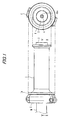
- the handle grip apparatus includes, as its main composing elements, a throttle grip 1, a magnet 6, an angle sensor 13 serving as a detector, a rotation side frictional plate 9 and a fixed side frictional plate 10 respectively disposed within a handle bar H, and an energizing member S1 and an adjusting mechanism (a bolt member 4 and an adjusting member 5) cooperating together in constituting a resistance adjustor.
- the throttle grip 1 is mounted on a leading end portion of the handle bar H of the motorcycle and can be rotated relative to the handle bar H coaxially therewith.
- An outer peripheral surface of the throttle grip 1 provides a grip portion which can be gripped by a driver, while the throttle grip 1 includes a flange portion 1a on a base end side thereof.
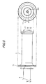
- a leading end face of the linking cylindrical member 2 includes an opening 2a formed substantially in a center thereof, while the tool fit-shape portion 4ba is allowed to face an outside through the opening 2a. That is, the bolt member 4 includes the tool fit-shape portion 4ba facing the leading end side of the throttle grip 1, whereby a tool can be fitted with the tool fit-shape portion 4ba and the bolt member 4 can be rotated using the tool.
- the tool fit-shape portion 4ba is formed to have a hexagonal shape with which a hexagonal wrench can be fitted.
- the magnet 6 Into the leading end (in the drawings, the left end including multiple leg portions) of the linking member 3, there is fitted the magnet 6, whereby the magnet 6 can be rotated together with the linking member 3.
- the magnet 6 when the throttle grip 1 is rotated, the magnet 6 is also rotated together with the linking cylindrical member 2 and linking member 3, whereby a magnetic field generated in the portion that faces the magnet 6 is allowed to vary according to the rotation angle of the magnet 6.
- the magnet 6 may be a permanent magnet or may be other type magnet (for example, a plastic magnet) which is capable of generating a magnetic field.
- the angle sensor 13 (a detector) is used to detect variations in the magnetic field of the magnet 6 in a non-contact manner and to detect the rotation angle of the throttle grip 1 according to the value of the detected magnetic field variation; and, the angle sensor 13 is made of a chip-shaped member formed in a base plate 12.
- the base plate 12 includes not only the angle sensor 13 capable of increasing or decreasing an output voltage according to variations in the magnetic field caused by the magnet 6 but also an amplifier portion for amplifying the output signal of the angle sensor 13. Use of such angle sensor 13 can facilitate the setting of a zero point (a signal of an initial position).
- the base plate 12 and angle sensor 13 are respectively stored within a storage member 11.
- the storage member 11 includes a storage space in the interior portion thereof and is fixed through a fixed cylindrical member 8 to the fixed member 7.
- a cord h which extends within the handle bar H and is used to send an amplified detection signal to the outside.
- reference numeral 14 designates a binding band which is used to fix the cord h.
- specific resin is filled into the storage member 11, whereby the base plate 12 can be molded with the resin.
- the fixed side frictional plate 10 On such side of the interior portion of the fixed cylindrical member 8 as faces the fixed member 7, there is fixed the fixed side frictional plate 10 and also there is disposed the rotation side frictional plate 9 in such a manner that the surface thereof is in contact with the fixed side frictional plate 10.
- the rotation side frictional plate 9 can be rotated together with the throttle grip 1 and also the surface thereof is pressed against the surface of the fixed side frictional plate 10 by an energizing member S1 made of a coil spring.
- an adjusting member 5 while the adjusting member 5 is structured such that it is allowed to slide in the longitudinal direction (in Fig. 3 , in the right and left direction) of the linking member 3. That is, in the adjusting member 5, as shown in Fig. 4 , there are formed multiple holes 5b in a concentric circle manner; and, when the leg portions of the linking member 3 are inserted into these holes 5b respectively, the adjusting member 5 is allowed to slide in the axial direction of the linking member 3 and is prevented from moving in the peripheral direction.
- the adjusting member 5 includes a burring portion 5a (rising portion) formed by burring the central portion of the adjusting member 5 and, in the inner periphery of the burring portion 5a, there is formed a female screw 5aa which can be engaged with the male screw 4a of the bolt member 4.
- a burring portion 5a (rising portion) formed by burring the central portion of the adjusting member 5 and, in the inner periphery of the burring portion 5a, there is formed a female screw 5aa which can be engaged with the male screw 4a of the bolt member 4.
- the adjusting member 5 is moved right in Fig. 3 (in a direction to approach the rotation side frictional plate 9) to thereby be able to decrease the whole length of the energizing member S1 made of a coil spring, whereby the urging force (pressing force) of the energizing member S1 to be applied onto the rotation side frictional plate 9 can be increased.
- This can increase the resistance generated when the throttle grip 1 is rotated and thus the rotation load of the throttle grip 1 can be increased.
- a spring S2 is contacted with the other surface 5d of the adjusting member 5.
- the other end of the spring S2 is contacted with the magnet 6, whereby the spring S2 is capable of pressing the magnet 6 against the surface 11a of the storage member 11.
- the magnet 6 is allowed to rotate together with the throttle grip 1 while it is pressed against the surface 11a of the storage member 11, thereby being able to prevent the spacing dimension of the magnet 6 relative to the angle sensor 13 from being shifted due to the vibrations of the motorcycle, which can enhance the precision of the throttle grip apparatus further.
- the adjusting member 5 is moved right or left in Fig. 3 , by decreasing or increasing the whole length of the coil spring S2, the pressing force of the magnet 6 on the surface 11a can be adjusted.
- the frictional plates (rotation side frictional plate 9 and fixed side frictional plate 10), when the throttle grip 1 is rotated, capable of generating the resistance and thus the rotation load of the throttle grip 1 are disposed within the handle bar H, even when the throttle wire is omitted, the throttle grip 1 can be operated with no uncomfortable feeling and also the size of the throttle grip apparatus can be reduced. Also, since the cord h for transmitting the detection signal of the angle sensor 13 to the outside is disposed so as to extend within the handle bar H, the handling of the cord h can be facilitated, which can enhance the design of the appearance of the throttle grip apparatus.
- a throttle grip apparatus similarly to the first embodiment, is used to detect the rotation angle of a throttle grip mounted on a handle bar of a motorcycle and to transmit the thus detected signal to an electronic control unit such as ECU mounted in the motorcycle.
- the present handle grip apparatus includes, as its main composing elements, a throttle grip 1, a magnet 6, an angle sensor 13, a rotation side frictional plate 9 and a fixed side frictional plate 10 respectively disposed within a handle bar H, and an energizing member S1 and an adjusting mechanism (a bolt member 4 and an adjusting member 5) cooperating together in constituting a resistance adjusting unit.
- the composing elements of the present embodiment similar to those of the first embodiment are given the same designations and thus the detailed description thereof is omitted here.
- a return spring 15' for energizing the throttle grip 1 in the initial position direction and also a spring receiver 16 fixed to the linking member 3, while one end of the return spring 15' is secured to the spring receiver 16. Also, the other end of the return spring 15' is secured to the fixed member 7.
- the invention is not limited to them.
- the frictional plates (rotation side frictional plate 9 and fixed side frictional plate 10) must be disposed within the handle bar H, but the resistance adjusting unit capable of arbitrarily adjusting the resistance to be generated the frictional plates may not be provided.
- the resistance adjusting unit is not limited to the above-mentioned embodiments but other various units are also possible, provided that they can arbitrarily adjust the resistance to be generated by the frictional plates.
- the throttle grip apparatus is mounted on the handle bar of the motorcycle but it may also be mounted on other types of vehicles including a handle bar (for example, an ATV and a snowmobile).
Landscapes
- Engineering & Computer Science (AREA)
- Mechanical Engineering (AREA)
- Chemical & Material Sciences (AREA)
- Combustion & Propulsion (AREA)
- General Engineering & Computer Science (AREA)
- Control Of Throttle Valves Provided In The Intake System Or In The Exhaust System (AREA)
- Steering Devices For Bicycles And Motorcycles (AREA)
- Measurement Of Length, Angles, Or The Like Using Electric Or Magnetic Means (AREA)
Applications Claiming Priority (1)
| Application Number | Priority Date | Filing Date | Title |
|---|---|---|---|
| JP2008329638A JP5311556B2 (ja) | 2008-12-25 | 2008-12-25 | スロットルグリップ装置 |
Publications (2)
| Publication Number | Publication Date |
|---|---|
| EP2202139A1 true EP2202139A1 (de) | 2010-06-30 |
| EP2202139B1 EP2202139B1 (de) | 2011-08-03 |
Family
ID=41622210
Family Applications (1)
| Application Number | Title | Priority Date | Filing Date |
|---|---|---|---|
| EP09179775A Not-in-force EP2202139B1 (de) | 2008-12-25 | 2009-12-18 | Drosselgriffvorrichtung |
Country Status (7)
| Country | Link |
|---|---|
| US (1) | US8336423B2 (de) |
| EP (1) | EP2202139B1 (de) |
| JP (1) | JP5311556B2 (de) |
| CN (1) | CN101761400A (de) |
| AT (1) | ATE518739T1 (de) |
| BR (1) | BRPI0905193A2 (de) |
| TW (1) | TWI491530B (de) |
Cited By (2)
| Publication number | Priority date | Publication date | Assignee | Title |
|---|---|---|---|---|
| FR3063043A1 (fr) * | 2017-02-23 | 2018-08-24 | Continental Automotive France | Systeme de commande d'un vehicule muni de commandes electriques |
| CN114559379A (zh) * | 2022-03-23 | 2022-05-31 | 潍坊路加精工有限公司 | 一种油门把手定位工装开闭装置 |
Families Citing this family (13)
| Publication number | Priority date | Publication date | Assignee | Title |
|---|---|---|---|---|
| DE102006060345A1 (de) * | 2006-12-20 | 2008-06-26 | Gustav Magenwirth Gmbh & Co. Kg | Griffrohr |
| JP5064342B2 (ja) * | 2008-09-19 | 2012-10-31 | 本田技研工業株式会社 | 鞍乗り型車両のスロットル開度検出装置 |
| JP5448148B2 (ja) * | 2009-06-05 | 2014-03-19 | 朝日電装株式会社 | スロットルグリップ装置 |
| DE102010013686A1 (de) * | 2010-04-01 | 2011-10-06 | Gustav Magenwirth Gmbh & Co. Kg | Gasdrehgriff |
| JP2012047624A (ja) * | 2010-08-27 | 2012-03-08 | Nippon Seiki Co Ltd | 位置検出装置 |
| JP5710949B2 (ja) * | 2010-12-03 | 2015-04-30 | 朝日電装株式会社 | スロットル装置 |
| US8869649B2 (en) * | 2011-07-12 | 2014-10-28 | Shimano Inc. | Bicycle shift operating device |
| US8887594B2 (en) * | 2012-02-17 | 2014-11-18 | Aks Engineering, Llc | Assembly for selectively locking the angular position of a biased throttle grip |
| JP2013203176A (ja) * | 2012-03-28 | 2013-10-07 | Nippon Seiki Co Ltd | 位置検出装置 |
| JP2018001883A (ja) * | 2016-06-28 | 2018-01-11 | 株式会社シマノ | 自転車用バーエンド |
| CN106428382B (zh) * | 2016-12-14 | 2022-06-03 | 上海东动科技有限公司 | 一种油门转把和电动车 |
| JP6940573B2 (ja) * | 2019-10-01 | 2021-09-29 | 本田技研工業株式会社 | 鞍乗型車両、および操作装置 |
| JP7431120B2 (ja) * | 2020-07-16 | 2024-02-14 | 東洋電装株式会社 | アクセルポジションセンサ |
Citations (6)
| Publication number | Priority date | Publication date | Assignee | Title |
|---|---|---|---|---|
| JPH04254278A (ja) | 1991-02-01 | 1992-09-09 | Yamaha Motor Co Ltd | 自動二輪車のスロットル開度センサ取付構造 |
| DE10027193A1 (de) * | 2000-05-31 | 2001-12-06 | Magenwirth Gmbh Co Gustav | Gasdrehgriff |
| EP1338502A1 (de) * | 2002-02-26 | 2003-08-27 | Yamaha Hatsudoki Kabushiki Kaisha | Apparat zum Feststellen der Öffnung der Drosselklappe |
| US20040107789A1 (en) * | 2002-12-06 | 2004-06-10 | Magneti Marelli Powertrain Usa, Inc. | Handlebar throttle controller with hysteresis |
| US20050251301A1 (en) * | 2004-04-23 | 2005-11-10 | Asahi Denso Co., Ltd. | Throttle grip apparatus |
| WO2008010186A2 (en) * | 2006-07-19 | 2008-01-24 | Bitron S.P.A. | A twist-grip control device, in particular for motor vehicles |
Family Cites Families (5)
| Publication number | Priority date | Publication date | Assignee | Title |
|---|---|---|---|---|
| US5134897A (en) * | 1989-10-20 | 1992-08-04 | Campagnolo S.R.L. | Twist-grip device for operating the gears of a bicycle |
| JP3078548B1 (ja) * | 1999-11-08 | 2000-08-21 | 健二 鈴木 | 自動二輪車用のスロットル開度保持ユニット |
| US7287512B2 (en) * | 2006-01-10 | 2007-10-30 | Harley-Davidson Motor Company Group, Inc. | Throttle position sensor |
| JP4846705B2 (ja) * | 2007-12-18 | 2011-12-28 | 本田技研工業株式会社 | 車両のスロットル装置 |
| JP5448148B2 (ja) * | 2009-06-05 | 2014-03-19 | 朝日電装株式会社 | スロットルグリップ装置 |
-
2008
- 2008-12-25 JP JP2008329638A patent/JP5311556B2/ja not_active Expired - Fee Related
-
2009
- 2009-12-17 TW TW098143335A patent/TWI491530B/zh not_active IP Right Cessation
- 2009-12-18 EP EP09179775A patent/EP2202139B1/de not_active Not-in-force
- 2009-12-18 AT AT09179775T patent/ATE518739T1/de not_active IP Right Cessation
- 2009-12-22 BR BRPI0905193-7A patent/BRPI0905193A2/pt not_active IP Right Cessation
- 2009-12-23 US US12/645,775 patent/US8336423B2/en not_active Expired - Fee Related
- 2009-12-25 CN CN200910249571.8A patent/CN101761400A/zh active Pending
Patent Citations (7)
| Publication number | Priority date | Publication date | Assignee | Title |
|---|---|---|---|---|
| JPH04254278A (ja) | 1991-02-01 | 1992-09-09 | Yamaha Motor Co Ltd | 自動二輪車のスロットル開度センサ取付構造 |
| DE10027193A1 (de) * | 2000-05-31 | 2001-12-06 | Magenwirth Gmbh Co Gustav | Gasdrehgriff |
| EP1338502A1 (de) * | 2002-02-26 | 2003-08-27 | Yamaha Hatsudoki Kabushiki Kaisha | Apparat zum Feststellen der Öffnung der Drosselklappe |
| JP2003252274A (ja) | 2002-02-26 | 2003-09-10 | Yamaha Motor Co Ltd | スロットル開度検出装置 |
| US20040107789A1 (en) * | 2002-12-06 | 2004-06-10 | Magneti Marelli Powertrain Usa, Inc. | Handlebar throttle controller with hysteresis |
| US20050251301A1 (en) * | 2004-04-23 | 2005-11-10 | Asahi Denso Co., Ltd. | Throttle grip apparatus |
| WO2008010186A2 (en) * | 2006-07-19 | 2008-01-24 | Bitron S.P.A. | A twist-grip control device, in particular for motor vehicles |
Cited By (8)
| Publication number | Priority date | Publication date | Assignee | Title |
|---|---|---|---|---|
| FR3063043A1 (fr) * | 2017-02-23 | 2018-08-24 | Continental Automotive France | Systeme de commande d'un vehicule muni de commandes electriques |
| WO2018154209A1 (fr) * | 2017-02-23 | 2018-08-30 | Continental Automotive France | Système de commande d'un véhicule muni de commandes électriques |
| CN110300841A (zh) * | 2017-02-23 | 2019-10-01 | 法国大陆汽车公司 | 配备有电气控制的车辆的控制系统 |
| KR20190116499A (ko) * | 2017-02-23 | 2019-10-14 | 콘티넨탈 오토모티브 프랑스 | 전기 제어부가 장착된 차량을 제어하기 위한 시스템 |
| US10723404B2 (en) | 2017-02-23 | 2020-07-28 | Continental Automotive France | System for controlling a vehicle fitted with electrical controls |
| CN110300841B (zh) * | 2017-02-23 | 2022-08-12 | 法国大陆汽车公司 | 配备有电气控制的车辆的控制系统 |
| CN114559379A (zh) * | 2022-03-23 | 2022-05-31 | 潍坊路加精工有限公司 | 一种油门把手定位工装开闭装置 |
| CN114559379B (zh) * | 2022-03-23 | 2023-12-01 | 潍坊路加精工有限公司 | 一种油门把手定位工装开闭装置 |
Also Published As
| Publication number | Publication date |
|---|---|
| TW201033071A (en) | 2010-09-16 |
| ATE518739T1 (de) | 2011-08-15 |
| BRPI0905193A2 (pt) | 2011-03-22 |
| TWI491530B (zh) | 2015-07-11 |
| EP2202139B1 (de) | 2011-08-03 |
| JP2010149684A (ja) | 2010-07-08 |
| JP5311556B2 (ja) | 2013-10-09 |
| CN101761400A (zh) | 2010-06-30 |
| US20100162848A1 (en) | 2010-07-01 |
| US8336423B2 (en) | 2012-12-25 |
Similar Documents
| Publication | Publication Date | Title |
|---|---|---|
| EP2202139B1 (de) | Drosselgriffvorrichtung | |
| EP2263933B1 (de) | Drosselgriffvorrichtung | |
| US8109123B2 (en) | Riveting unit for electric rivet gun | |
| JP4063435B2 (ja) | 自動車 | |
| EP3498582B1 (de) | Drosselklappen-drehgriff | |
| JP2005075320A (ja) | ペダル反力装置 | |
| US9428247B2 (en) | Control device | |
| JP5442323B2 (ja) | スロットルグリップ装置 | |
| JP2004339945A (ja) | スロットルグリップ装置 | |
| US7823472B2 (en) | Shift control device for vehicle, and vehicle including the shift control device | |
| US7412906B2 (en) | Steering system torque sensor | |
| JP6855892B2 (ja) | アクセル操作装置 | |
| JP2019082151A (ja) | スロットルグリップ装置 | |
| JP5180055B2 (ja) | スロットルグリップ装置 | |
| JP5254345B2 (ja) | 車輌のレンジ切換え装置 | |
| US8505704B2 (en) | Apparatus for operating clutch | |
| JPH07232647A (ja) | パワーステアリング装置の操舵トルク検出装置 | |
| JP4867278B2 (ja) | 張力センサ及び電動パーキングブレーキ | |
| JP2001175345A (ja) | 自動車のペダル装置及びこれに用いられるダンパ | |
| JP2021021355A (ja) | スロットルグリップ装置 | |
| JP2024058441A (ja) | スロットルグリップ装置 | |
| EP1342638A3 (de) | Lenkausstattung für ein Fahrzeug | |
| JP2024058440A (ja) | スロットルグリップ装置 |
Legal Events
| Date | Code | Title | Description |
|---|---|---|---|
| PUAI | Public reference made under article 153(3) epc to a published international application that has entered the european phase |
Free format text: ORIGINAL CODE: 0009012 |
|
| AK | Designated contracting states |
Kind code of ref document: A1 Designated state(s): AT BE BG CH CY CZ DE DK EE ES FI FR GB GR HR HU IE IS IT LI LT LU LV MC MK MT NL NO PL PT RO SE SI SK SM TR |
|
| AX | Request for extension of the european patent |
Extension state: AL BA RS |
|
| 17P | Request for examination filed |
Effective date: 20101111 |
|
| GRAP | Despatch of communication of intention to grant a patent |
Free format text: ORIGINAL CODE: EPIDOSNIGR1 |
|
| GRAS | Grant fee paid |
Free format text: ORIGINAL CODE: EPIDOSNIGR3 |
|
| GRAA | (expected) grant |
Free format text: ORIGINAL CODE: 0009210 |
|
| AK | Designated contracting states |
Kind code of ref document: B1 Designated state(s): AT BE BG CH CY CZ DE DK EE ES FI FR GB GR HR HU IE IS IT LI LT LU LV MC MK MT NL NO PL PT RO SE SI SK SM TR |
|
| REG | Reference to a national code |
Ref country code: GB Ref legal event code: FG4D |
|
| REG | Reference to a national code |
Ref country code: CH Ref legal event code: EP |
|
| REG | Reference to a national code |
Ref country code: IE Ref legal event code: FG4D |
|
| REG | Reference to a national code |
Ref country code: DE Ref legal event code: R096 Ref document number: 602009001978 Country of ref document: DE Effective date: 20110929 |
|
| REG | Reference to a national code |
Ref country code: NL Ref legal event code: VDEP Effective date: 20110803 |
|
| LTIE | Lt: invalidation of european patent or patent extension |
Effective date: 20110803 |
|
| PG25 | Lapsed in a contracting state [announced via postgrant information from national office to epo] |
Ref country code: SE Free format text: LAPSE BECAUSE OF FAILURE TO SUBMIT A TRANSLATION OF THE DESCRIPTION OR TO PAY THE FEE WITHIN THE PRESCRIBED TIME-LIMIT Effective date: 20110803 Ref country code: FI Free format text: LAPSE BECAUSE OF FAILURE TO SUBMIT A TRANSLATION OF THE DESCRIPTION OR TO PAY THE FEE WITHIN THE PRESCRIBED TIME-LIMIT Effective date: 20110803 Ref country code: NL Free format text: LAPSE BECAUSE OF FAILURE TO SUBMIT A TRANSLATION OF THE DESCRIPTION OR TO PAY THE FEE WITHIN THE PRESCRIBED TIME-LIMIT Effective date: 20110803 Ref country code: LT Free format text: LAPSE BECAUSE OF FAILURE TO SUBMIT A TRANSLATION OF THE DESCRIPTION OR TO PAY THE FEE WITHIN THE PRESCRIBED TIME-LIMIT Effective date: 20110803 Ref country code: PT Free format text: LAPSE BECAUSE OF FAILURE TO SUBMIT A TRANSLATION OF THE DESCRIPTION OR TO PAY THE FEE WITHIN THE PRESCRIBED TIME-LIMIT Effective date: 20111205 Ref country code: NO Free format text: LAPSE BECAUSE OF FAILURE TO SUBMIT A TRANSLATION OF THE DESCRIPTION OR TO PAY THE FEE WITHIN THE PRESCRIBED TIME-LIMIT Effective date: 20111103 Ref country code: HR Free format text: LAPSE BECAUSE OF FAILURE TO SUBMIT A TRANSLATION OF THE DESCRIPTION OR TO PAY THE FEE WITHIN THE PRESCRIBED TIME-LIMIT Effective date: 20110803 Ref country code: IS Free format text: LAPSE BECAUSE OF FAILURE TO SUBMIT A TRANSLATION OF THE DESCRIPTION OR TO PAY THE FEE WITHIN THE PRESCRIBED TIME-LIMIT Effective date: 20111203 |
|
| REG | Reference to a national code |
Ref country code: AT Ref legal event code: MK05 Ref document number: 518739 Country of ref document: AT Kind code of ref document: T Effective date: 20110803 |
|
| PG25 | Lapsed in a contracting state [announced via postgrant information from national office to epo] |
Ref country code: AT Free format text: LAPSE BECAUSE OF FAILURE TO SUBMIT A TRANSLATION OF THE DESCRIPTION OR TO PAY THE FEE WITHIN THE PRESCRIBED TIME-LIMIT Effective date: 20110803 Ref country code: GR Free format text: LAPSE BECAUSE OF FAILURE TO SUBMIT A TRANSLATION OF THE DESCRIPTION OR TO PAY THE FEE WITHIN THE PRESCRIBED TIME-LIMIT Effective date: 20111104 Ref country code: PL Free format text: LAPSE BECAUSE OF FAILURE TO SUBMIT A TRANSLATION OF THE DESCRIPTION OR TO PAY THE FEE WITHIN THE PRESCRIBED TIME-LIMIT Effective date: 20110803 Ref country code: SI Free format text: LAPSE BECAUSE OF FAILURE TO SUBMIT A TRANSLATION OF THE DESCRIPTION OR TO PAY THE FEE WITHIN THE PRESCRIBED TIME-LIMIT Effective date: 20110803 Ref country code: CY Free format text: LAPSE BECAUSE OF FAILURE TO SUBMIT A TRANSLATION OF THE DESCRIPTION OR TO PAY THE FEE WITHIN THE PRESCRIBED TIME-LIMIT Effective date: 20110803 Ref country code: LV Free format text: LAPSE BECAUSE OF FAILURE TO SUBMIT A TRANSLATION OF THE DESCRIPTION OR TO PAY THE FEE WITHIN THE PRESCRIBED TIME-LIMIT Effective date: 20110803 |
|
| PG25 | Lapsed in a contracting state [announced via postgrant information from national office to epo] |
Ref country code: BE Free format text: LAPSE BECAUSE OF FAILURE TO SUBMIT A TRANSLATION OF THE DESCRIPTION OR TO PAY THE FEE WITHIN THE PRESCRIBED TIME-LIMIT Effective date: 20110803 |
|
| PG25 | Lapsed in a contracting state [announced via postgrant information from national office to epo] |
Ref country code: CZ Free format text: LAPSE BECAUSE OF FAILURE TO SUBMIT A TRANSLATION OF THE DESCRIPTION OR TO PAY THE FEE WITHIN THE PRESCRIBED TIME-LIMIT Effective date: 20110803 Ref country code: SK Free format text: LAPSE BECAUSE OF FAILURE TO SUBMIT A TRANSLATION OF THE DESCRIPTION OR TO PAY THE FEE WITHIN THE PRESCRIBED TIME-LIMIT Effective date: 20110803 |
|
| PG25 | Lapsed in a contracting state [announced via postgrant information from national office to epo] |
Ref country code: EE Free format text: LAPSE BECAUSE OF FAILURE TO SUBMIT A TRANSLATION OF THE DESCRIPTION OR TO PAY THE FEE WITHIN THE PRESCRIBED TIME-LIMIT Effective date: 20110803 Ref country code: RO Free format text: LAPSE BECAUSE OF FAILURE TO SUBMIT A TRANSLATION OF THE DESCRIPTION OR TO PAY THE FEE WITHIN THE PRESCRIBED TIME-LIMIT Effective date: 20110803 |
|
| PLBE | No opposition filed within time limit |
Free format text: ORIGINAL CODE: 0009261 |
|
| STAA | Information on the status of an ep patent application or granted ep patent |
Free format text: STATUS: NO OPPOSITION FILED WITHIN TIME LIMIT |
|
| PG25 | Lapsed in a contracting state [announced via postgrant information from national office to epo] |
Ref country code: DK Free format text: LAPSE BECAUSE OF FAILURE TO SUBMIT A TRANSLATION OF THE DESCRIPTION OR TO PAY THE FEE WITHIN THE PRESCRIBED TIME-LIMIT Effective date: 20110803 |
|
| 26N | No opposition filed |
Effective date: 20120504 |
|
| PG25 | Lapsed in a contracting state [announced via postgrant information from national office to epo] |
Ref country code: MC Free format text: LAPSE BECAUSE OF NON-PAYMENT OF DUE FEES Effective date: 20111231 |
|
| REG | Reference to a national code |
Ref country code: DE Ref legal event code: R097 Ref document number: 602009001978 Country of ref document: DE Effective date: 20120504 |
|
| REG | Reference to a national code |
Ref country code: IE Ref legal event code: MM4A |
|
| PG25 | Lapsed in a contracting state [announced via postgrant information from national office to epo] |
Ref country code: IE Free format text: LAPSE BECAUSE OF NON-PAYMENT OF DUE FEES Effective date: 20111218 |
|
| PG25 | Lapsed in a contracting state [announced via postgrant information from national office to epo] |
Ref country code: MT Free format text: LAPSE BECAUSE OF FAILURE TO SUBMIT A TRANSLATION OF THE DESCRIPTION OR TO PAY THE FEE WITHIN THE PRESCRIBED TIME-LIMIT Effective date: 20110803 Ref country code: MK Free format text: LAPSE BECAUSE OF FAILURE TO SUBMIT A TRANSLATION OF THE DESCRIPTION OR TO PAY THE FEE WITHIN THE PRESCRIBED TIME-LIMIT Effective date: 20110803 |
|
| PG25 | Lapsed in a contracting state [announced via postgrant information from national office to epo] |
Ref country code: SM Free format text: LAPSE BECAUSE OF FAILURE TO SUBMIT A TRANSLATION OF THE DESCRIPTION OR TO PAY THE FEE WITHIN THE PRESCRIBED TIME-LIMIT Effective date: 20110803 |
|
| PG25 | Lapsed in a contracting state [announced via postgrant information from national office to epo] |
Ref country code: LU Free format text: LAPSE BECAUSE OF NON-PAYMENT OF DUE FEES Effective date: 20111218 |
|
| PG25 | Lapsed in a contracting state [announced via postgrant information from national office to epo] |
Ref country code: BG Free format text: LAPSE BECAUSE OF FAILURE TO SUBMIT A TRANSLATION OF THE DESCRIPTION OR TO PAY THE FEE WITHIN THE PRESCRIBED TIME-LIMIT Effective date: 20111103 |
|
| PG25 | Lapsed in a contracting state [announced via postgrant information from national office to epo] |
Ref country code: TR Free format text: LAPSE BECAUSE OF FAILURE TO SUBMIT A TRANSLATION OF THE DESCRIPTION OR TO PAY THE FEE WITHIN THE PRESCRIBED TIME-LIMIT Effective date: 20110803 |
|
| PG25 | Lapsed in a contracting state [announced via postgrant information from national office to epo] |
Ref country code: ES Free format text: LAPSE BECAUSE OF FAILURE TO SUBMIT A TRANSLATION OF THE DESCRIPTION OR TO PAY THE FEE WITHIN THE PRESCRIBED TIME-LIMIT Effective date: 20111114 Ref country code: HU Free format text: LAPSE BECAUSE OF FAILURE TO SUBMIT A TRANSLATION OF THE DESCRIPTION OR TO PAY THE FEE WITHIN THE PRESCRIBED TIME-LIMIT Effective date: 20110803 |
|
| REG | Reference to a national code |
Ref country code: CH Ref legal event code: PL |
|
| PG25 | Lapsed in a contracting state [announced via postgrant information from national office to epo] |
Ref country code: LI Free format text: LAPSE BECAUSE OF NON-PAYMENT OF DUE FEES Effective date: 20131231 Ref country code: CH Free format text: LAPSE BECAUSE OF NON-PAYMENT OF DUE FEES Effective date: 20131231 |
|
| REG | Reference to a national code |
Ref country code: FR Ref legal event code: PLFP Year of fee payment: 7 |
|
| REG | Reference to a national code |
Ref country code: FR Ref legal event code: PLFP Year of fee payment: 8 |
|
| REG | Reference to a national code |
Ref country code: FR Ref legal event code: PLFP Year of fee payment: 9 |
|
| PGFP | Annual fee paid to national office [announced via postgrant information from national office to epo] |
Ref country code: GB Payment date: 20211028 Year of fee payment: 13 Ref country code: FR Payment date: 20211109 Year of fee payment: 13 Ref country code: DE Payment date: 20211102 Year of fee payment: 13 |
|
| PGFP | Annual fee paid to national office [announced via postgrant information from national office to epo] |
Ref country code: IT Payment date: 20211110 Year of fee payment: 13 |
|
| REG | Reference to a national code |
Ref country code: DE Ref legal event code: R119 Ref document number: 602009001978 Country of ref document: DE |
|
| GBPC | Gb: european patent ceased through non-payment of renewal fee |
Effective date: 20221218 |
|
| PG25 | Lapsed in a contracting state [announced via postgrant information from national office to epo] |
Ref country code: GB Free format text: LAPSE BECAUSE OF NON-PAYMENT OF DUE FEES Effective date: 20221218 Ref country code: DE Free format text: LAPSE BECAUSE OF NON-PAYMENT OF DUE FEES Effective date: 20230701 |
|
| PG25 | Lapsed in a contracting state [announced via postgrant information from national office to epo] |
Ref country code: FR Free format text: LAPSE BECAUSE OF NON-PAYMENT OF DUE FEES Effective date: 20221231 |
|
| PG25 | Lapsed in a contracting state [announced via postgrant information from national office to epo] |
Ref country code: IT Free format text: LAPSE BECAUSE OF NON-PAYMENT OF DUE FEES Effective date: 20221218 |