EP2202153A2 - Monolithische Struktur zur Montage eines Flugzeugmotors - Google Patents
Monolithische Struktur zur Montage eines Flugzeugmotors Download PDFInfo
- Publication number
- EP2202153A2 EP2202153A2 EP09179291A EP09179291A EP2202153A2 EP 2202153 A2 EP2202153 A2 EP 2202153A2 EP 09179291 A EP09179291 A EP 09179291A EP 09179291 A EP09179291 A EP 09179291A EP 2202153 A2 EP2202153 A2 EP 2202153A2
- Authority
- EP
- European Patent Office
- Prior art keywords
- assembly
- monolithic structure
- aircraft
- gas turbine
- nacelle
- Prior art date
- Legal status (The legal status is an assumption and is not a legal conclusion. Google has not performed a legal analysis and makes no representation as to the accuracy of the status listed.)
- Granted
Links
- 238000000034 method Methods 0.000 claims description 7
- 239000002131 composite material Substances 0.000 claims description 2
- 239000004593 Epoxy Substances 0.000 claims 1
- 238000006073 displacement reaction Methods 0.000 claims 1
- 239000000835 fiber Substances 0.000 claims 1
- 238000005452 bending Methods 0.000 description 7
- 230000005540 biological transmission Effects 0.000 description 2
- 230000002829 reductive effect Effects 0.000 description 2
- 230000003068 static effect Effects 0.000 description 2
- 229920000049 Carbon (fiber) Polymers 0.000 description 1
- 230000002411 adverse Effects 0.000 description 1
- 230000000712 assembly Effects 0.000 description 1
- 238000000429 assembly Methods 0.000 description 1
- 230000015572 biosynthetic process Effects 0.000 description 1
- 239000004917 carbon fiber Substances 0.000 description 1
- 230000001066 destructive effect Effects 0.000 description 1
- 230000000694 effects Effects 0.000 description 1
- 238000009434 installation Methods 0.000 description 1
- 230000013011 mating Effects 0.000 description 1
- VNWKTOKETHGBQD-UHFFFAOYSA-N methane Chemical compound C VNWKTOKETHGBQD-UHFFFAOYSA-N 0.000 description 1
- 230000036961 partial effect Effects 0.000 description 1
- 238000009419 refurbishment Methods 0.000 description 1
- 230000008439 repair process Effects 0.000 description 1
- 230000000717 retained effect Effects 0.000 description 1
- 239000013585 weight reducing agent Substances 0.000 description 1
Images




Classifications
-
- B—PERFORMING OPERATIONS; TRANSPORTING
- B64—AIRCRAFT; AVIATION; COSMONAUTICS
- B64D—EQUIPMENT FOR FITTING IN OR TO AIRCRAFT; FLIGHT SUITS; PARACHUTES; ARRANGEMENT OR MOUNTING OF POWER PLANTS OR PROPULSION TRANSMISSIONS IN AIRCRAFT
- B64D27/00—Arrangement or mounting of power plants in aircraft; Aircraft characterised by the type or position of power plants
- B64D27/02—Aircraft characterised by the type or position of power plants
- B64D27/16—Aircraft characterised by the type or position of power plants of jet type
- B64D27/18—Aircraft characterised by the type or position of power plants of jet type within, or attached to, wings
-
- B—PERFORMING OPERATIONS; TRANSPORTING
- B64—AIRCRAFT; AVIATION; COSMONAUTICS
- B64D—EQUIPMENT FOR FITTING IN OR TO AIRCRAFT; FLIGHT SUITS; PARACHUTES; ARRANGEMENT OR MOUNTING OF POWER PLANTS OR PROPULSION TRANSMISSIONS IN AIRCRAFT
- B64D27/00—Arrangement or mounting of power plants in aircraft; Aircraft characterised by the type or position of power plants
- B64D27/40—Arrangements for mounting power plants in aircraft
- B64D27/404—Suspension arrangements specially adapted for supporting vertical loads
-
- B—PERFORMING OPERATIONS; TRANSPORTING
- B64—AIRCRAFT; AVIATION; COSMONAUTICS
- B64D—EQUIPMENT FOR FITTING IN OR TO AIRCRAFT; FLIGHT SUITS; PARACHUTES; ARRANGEMENT OR MOUNTING OF POWER PLANTS OR PROPULSION TRANSMISSIONS IN AIRCRAFT
- B64D27/00—Arrangement or mounting of power plants in aircraft; Aircraft characterised by the type or position of power plants
- B64D27/40—Arrangements for mounting power plants in aircraft
- B64D27/406—Suspension arrangements specially adapted for supporting thrust loads, e.g. thrust links
-
- B—PERFORMING OPERATIONS; TRANSPORTING
- B64—AIRCRAFT; AVIATION; COSMONAUTICS
- B64D—EQUIPMENT FOR FITTING IN OR TO AIRCRAFT; FLIGHT SUITS; PARACHUTES; ARRANGEMENT OR MOUNTING OF POWER PLANTS OR PROPULSION TRANSMISSIONS IN AIRCRAFT
- B64D29/00—Power-plant nacelles, fairings or cowlings
-
- Y—GENERAL TAGGING OF NEW TECHNOLOGICAL DEVELOPMENTS; GENERAL TAGGING OF CROSS-SECTIONAL TECHNOLOGIES SPANNING OVER SEVERAL SECTIONS OF THE IPC; TECHNICAL SUBJECTS COVERED BY FORMER USPC CROSS-REFERENCE ART COLLECTIONS [XRACs] AND DIGESTS
- Y02—TECHNOLOGIES OR APPLICATIONS FOR MITIGATION OR ADAPTATION AGAINST CLIMATE CHANGE
- Y02T—CLIMATE CHANGE MITIGATION TECHNOLOGIES RELATED TO TRANSPORTATION
- Y02T50/00—Aeronautics or air transport
- Y02T50/40—Weight reduction
Definitions
- This invention relates generally to aircraft engine assemblies, and more specifically to structures for mounting and encasing aircraft engines.
- a current design practice is to attach the engine inlet to the fan case by a bolted flange.
- the fan case is covered by fan cowls which are attached to a pylon structure.
- the fan case is attached by a bolted flange to a fan frame containing bearings to transmit the engine thrust from the fan rotor to the pylon through a conventional mount system attached to the fan frame at the 12:00 position at its outer diameter and/or at the fan frame hub.
- the core module is attached to the hub of the fan frame by a bolted flange.
- a thrust reverser assembly may be attached to a v-groove around the fan frame circumference and sometimes by a v-groove on the fan frame hub circumference.
- the thrust reverser assembly may be attached to the pylon by hinged lugs that allow movement fore and aft.
- the engine is supported at its aft end by a mount that attaches to the pylon.
- Thrust links are sometimes used to transmit the engine thrust to the pylon structure and thereby reduce bending moments in the structure. Inlet overturning moments are transmitted through the mount system to the pylon.
- turbofans are considered ready for installation when the fan and inlet are assembled to the remaining engine components.
- the fan and inlet may remain attached to the engine components, although the turbofan overhaul practices typically involve refurbishment of the core module of the engine with limited need for fan module work.
- removal of the fan module during the engine overhaul process leads to wasted shop floor space.
- the inlet and often the fan module may be removed for engine transport due to cargo aircraft door opening restrictions and roadway obstructions.
- the nacelle may experience an applied nacelle maneuvering force distributed nonuniformly over the nacelle surface both axially and circumferentially.
- the applied nacelle maneuvering force can significantly deflect and distort or ovalize the nacelle and/or fan case.
- this applied nacelle maneuvering force is transmitted around the circumference of the nacelle, from the inlet to the fan case and then through the fan struts to the core case, where it is reacted at the forward and aft mount link sets.
- the reaction forces tend to bend the cases and cause the adverse effects previously described.
- all of the forces and torques acting on the engine or nacelle are transferred to the pylon, which is usually includes a substantial structure.
- the above-mentioned need or needs may be addressed by various exemplary embodiments which provide an assembly comprising a monolithic structure.
- the exemplary monolithic structure includes an integral nacelle portion and a support structure portion.
- the nacelle portion generally comprises a body of rotation about an axial centerline and including an inlet region and a fan case region cooperating to define an annular wall bounding an axial channel.
- the monolithic structure further includes a ring member disposed in the axial channel. A plurality of radial elements extends from the ring member to the annular wall.
- the support structure portion generally extends in an axial direction, and includes a forward section integral with the nacelle portion and having an inlet stiffening region disposed radially outward of the annular wall.
- the support structure includes an aft section having at least one aircraft mount region.
- the monolithic structure is attachable to an associated aircraft at the aircraft mount region. When mounted on an associated aircraft, the nacelle portion and the support structure portion cooperate to form a first load path operable to transmit an applied nacelle maneuvering force directly to the associated aircraft.
- the assembly includes a selectively removable gas turbine engine mounted in supporting connection with the monolithic structure so that an engine centerline is substantially coextensive with the centerline of the nacelle portion.
- the assembly further includes a first assembly mounting the gas turbine engine to the monolithic structure at the aft section of the support structure portion; and a non-rigid interface between the gas turbine engine and the ring member non-rigidly mounting the gas turbine engine to the ring member, wherein, the gas turbine engine is substantially isolated from being acted on by the applied nacelle maneuvering force, when present.
- an assembly comprises an aircraft and a monolithic structure mounted in supporting connection with the aircraft.
- the monolithic structure includes an integral nacelle portion and a support structure portion.
- the nacelle portion generally comprises a body of rotation about an axial centerline and including an inlet region and a fan case region cooperating to define an annular wall bounding an axial channel.
- the monolithic structure further includes a ring member disposed in the axial channel. A plurality of radial elements extends from the ring member to the annular wall.
- the support structure portion generally extends in an axial direction, and includes a forward section integral with the nacelle portion and having an inlet stiffening region disposed radially outward of the annular wall.
- the support structure includes an aft section having at least one aircraft mount region.
- An exemplary embodiment provides a method of mounting an aircraft engine to an associated aircraft.
- the exemplary method includes providing an integral monolithic structure; mounting a gas turbine engine to the monolithic structure at an aft mount region; and non-rigidly interfacing the gas turbine engine with the monolithic structure at a non-rigid interface between the gas turbine engine and the monolithic structure.
- FIG. 1 illustrates a typical engine mounting arrangement as known in the art.
- a nacelle 120 includes an inlet 122 firmly secured, as by a bolted joint 124 to the fan case 125, an intermediate fairing 126 which is a pair of essentially 180° access doors connected by hinges 148 to a forward extension 146 of the pylon 140, and an aft fairing 128 including two essentially 180° fan duct outer walls 130, each connected by hinges 147 to the pylon 140, and an inner core cowl 132.
- a plurality of fan struts, as represented by struts 134, extend generally radially to connect the fan case 125 to the core case 136.
- Three sets of mount links 152, 154, 156 connect the engine to the pylon 140 which itself is attached to the aircraft at pylon-to-aircraft mount fittings 142, 144.
- Forward mount link set 152 is a set of two links that transmit vertical and lateral forces
- axial mount link set 154 is a set of two links that transmit axial forces
- aft mount link set 156 is a set of three links located aft of the forward link set to transmit vertical forces, lateral forces and torque.
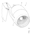
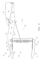
- FIGS. 2-3 generally show an assembly 10 which includes an integral monolithic structure 12 adapted for direct, semi-permanent attachment to an associated aircraft 13.
- the terms "integral” and “integrated” used throughout the text of this application and the appended claims are intended to mean items with are integrally joined or manufactured such that disassembly (in a typical non-destructive sense) is not possible.
- the monolithic structure 12 may be retained in supporting connection with the aircraft, as is explained in greater detail below.
- the monolithic structure includes a nacelle portion 14 and a support structure portion 16.
- the assembly 10 may include a thrust reverser assembly 60 as discussed in greater detail below.
- an exemplary nacelle portion 14 generally comprises a body of rotation 18 about an axial centerline 20.
- the nacelle portion 14 includes an inlet region 22 and a fan case region 24.
- the inlet region 22 and the fan case region 24 are integrally formed and cooperate to define an annular wall 26 bounding an axial channel 28.
- a ring member 30 is disposed within the axial channel 28 and is supported there through a plurality of radial elements 34 extending from the ring member 30 to the annular wall 26. Ring member 30 is dimensioned to receive at least a portion of a gas turbine engine therethrough as detailed below.
- Radial elements 30 may be configured as flow-directing elements or vanes as will be appreciated by those with skill in the art.
- the annular wall 26, radial elements 34 and ring member 30 are integrally formed or joined as part of the monolithic structure 12.
- the body of rotation 18 is arranged and dimensioned to encircle and encase a fan assembly 38 of a gas turbine engine assembly 70 ( FIG. 5 ).
- the monolithic structure 12 further includes an axially extending support structure portion 16 having a forward section 40 integral with the nacelle portion 14.
- An inlet stiffening region 42 is disposed in the forward section 40 and generally radially outward of the annular wall 26.
- the inlet stiffening region provides structural support forward of a traditional attachment site for a pylon.
- the inlet stiffening region extends circumferentially up to about 180° about the nacelle portion 14.
- the inlet stiffening region may, for example, comprise a greater thickness than the remainder of the nacelle portion 14.
- the inlet stiffening region may comprise structural and/or stiffening elements, such as honeycomb structures as is known in the art. Other inlet stiffening means may be contemplated by those having skill in the art.
- the support structure portion 16 extends aft of the body of rotation 18 and includes one or more aerodynamic surfaces.
- the support structure portion 16 also includes an aft section 44 defining at least one aircraft mount region 48.
- the nacelle portion 14 and the support structure 16 cooperate to form a first load path, indicated by arrows 50, for distributing static and dynamic loads transmitted between the engine and the airplane.
- the monolithic structure may be mounted under an aircraft wing as depicted in FIGS. 2-4 , or may be attached to any other appropriate point, for example, on top of a wing, or the fuselage, or other appendage of the aircraft.
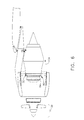
- an exemplary assembly 10 includes a gas turbine engine assembly 70 mounted in supported connection with the monolithic structure 12.
- a first mounting assembly 72 mounts the gas turbine engine assembly 70 to the monolithic structure 12 at the aft section 44 of the support structure portion 16 at an engine mount site 76.
- the first mounting assembly 72 may include a turbine ring 74 and an aft frame hanger 78 as is well known in the art.
- the assembly includes a non-rigid interface 80 between the gas turbine engine assembly 70 and the ring member 30 of the monolithic structure 12.
- the non-rigid interface substantially isolates the gas turbine engine from being acted on by an applied nacelle maneuvering force that are reacted along the load path 50 as earlier described.
- the non-rigid interface allows axial and circumferential relative movement between the nacelle portion 14 of the monolithic structure and the gas turbine engine assembly.
- the non-rigid interface may comprise a slip-joint arrangement, a spherical bearing, a link arrangement, a yoke with bearings at the 3 o'clock and 9 o'clock positions, a flexible diaphragm, or other arrangement that reduces transmission of the applied nacelle maneuvering force through the engine core.
- the monolithic structure 12 includes a containment system 82 at the annular wall 26 for fan blade out events.
- the monolithic structure may comprise in whole or in part, composite material, such as reinforced carbon fiber as is known in the art.
- the containment system is integrally formed at the time of formation of other portions of the monolithic structure.
- the containment system may be substantially formed separate from other portions of the monolithic structure, and then integrally joined thereto.
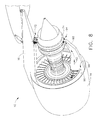
- the ring member 30 of the monolithic structure 12 is arranged and dimensioned for receiving at least a portion of the gas turbine engine therethrough including the compressor inlet 84.
- the fan assembly 38 may be disassembled and removed from the remainder of the gas turbine engine assembly including the engine core.
- the remainder of the gas turbine engine is configured and dimensioned for rearward removal from the monolithic structure.
- various attachments, bolts, and mounting fixtures may be disengaged to allow rearward movement of the remainder of the gas turbine engine.
- FIGS. 7 and 8 are directed to an alternate embodiment of assembly 10.
- This alternate embodiment includes a lower axially extending support member 90 operationally positionable generally opposite the support structure portion 16.
- the lower support member 90 extends between the nacelle portion 14 turbine ring 74 of the first mounting assembly 72.
- the lower support member is a structural member able to provide at least a portion of a lower load path, designated by arrow 92.
- the lower load path is able to transmit static and dynamic forces, including at least a portion of an applied nacelle maneuvering force, to the associated aircraft along the lower load path 92.
- the lower support member 90 may be a unitary member as illustrated in FIG.
- the lower support member 90 may be part of a thrust reverser assembly 60.
- a thrust reverser assembly may comprise a pair of clamshell doors.
- the lower support member 90 may be fashioned as mating sidewalls of a thrust reverser assembly.
- at least one load transferring assembly 94 such as a pin-in-slot arrangement or tangential links, is selectively engageable between the gas turbine engine and the thrust reverser assembly.
- the forward face 96 of the lower support member 90 may be engageable with the monolithic structure through a v-groove/v-blade arrangement 98.
- the thrust reverser assembly 60 may interface with the monolithic structure at a plurality of v-groove/v-blade attachment locations 98 as is well known in the art.
- the structural arrangements disclosed herein provide transmission of the inlet lift load or applied nacelle maneuvering forces directly to the support structure portion 16 instead of through the engine carcass.
- engine thrust loads are carried through thrust links 100 attached at the engine mount site 76 and at the ring member 30 of the monolithic structure 12 with a line of action that intersects the centerline of the engine at the plane of the fan.
- An exemplary method includes providing an integral monolithic structure that includes a body of rotation 18 about a centerline.
- the body of rotation 18 is dimensioned to circumscribe at least a fan assembly 38 of a gas turbine engine assembly 70.
- the gas turbine engine assembly 70 is mounted to the monolithic structure at an aft engine mount site 76.
- the engine mount site is located aft of the nacelle portion 14.
- the gas turbine engine assembly interfaces with the monolithic structure at a non-rigid interface 80.
- the monolithic structure 12 is attached to the associated aircraft at an aircraft mount region 48.
- the engine assembly 70 is removed from the associated aircraft 13 by removing fan assembly 38, detaching the engine assembly from engine mount site 76, and disengagement at the non-rigid interface 80.
- the remainder of the engine assembly may thus be displaced rearwardly from the monolithic structure 12, as indicated by arrow 104.
- Exemplary embodiments disclosed herein reduce backbone bending caused by reaction of applied maneuvering forces along the core engine to a pylon.
- the exemplary monolithic structure provides a flow path external to the core engine.
- Sufficient stiffening of the inlet and, in certain embodiments, an axially extending lower support structure reduce ovalization of the nacelle region, thus maintaining tip clearances between the fan blades and the annular wall to improve engine efficiency.
- Each exemplary embodiment disclosed herein may include certain features detailed in descriptions of other exemplary embodiments within the scope of the present invention.
Landscapes
- Engineering & Computer Science (AREA)
- Aviation & Aerospace Engineering (AREA)
- Structures Of Non-Positive Displacement Pumps (AREA)
- Connection Of Plates (AREA)
- Tires In General (AREA)
Applications Claiming Priority (1)
| Application Number | Priority Date | Filing Date | Title |
|---|---|---|---|
| US12/343,833 US8469309B2 (en) | 2008-12-24 | 2008-12-24 | Monolithic structure for mounting aircraft engine |
Publications (3)
| Publication Number | Publication Date |
|---|---|
| EP2202153A2 true EP2202153A2 (de) | 2010-06-30 |
| EP2202153A3 EP2202153A3 (de) | 2013-04-10 |
| EP2202153B1 EP2202153B1 (de) | 2016-08-10 |
Family
ID=41694622
Family Applications (1)
| Application Number | Title | Priority Date | Filing Date |
|---|---|---|---|
| EP09179291.1A Not-in-force EP2202153B1 (de) | 2008-12-24 | 2009-12-15 | Monolithische Struktur zur Montage eines Flugzeugmotors |
Country Status (7)
| Country | Link |
|---|---|
| US (1) | US8469309B2 (de) |
| EP (1) | EP2202153B1 (de) |
| CN (1) | CN101774430A (de) |
| BR (1) | BRPI0905496A2 (de) |
| CA (1) | CA2688780C (de) |
| IL (1) | IL202845A (de) |
| MX (1) | MX2009013842A (de) |
Cited By (8)
| Publication number | Priority date | Publication date | Assignee | Title |
|---|---|---|---|---|
| WO2012170404A1 (en) * | 2011-06-06 | 2012-12-13 | General Electric Company | System and method for mounting an aircraft engine |
| EP2537755A2 (de) | 2011-06-22 | 2012-12-26 | Rolls-Royce plc | Montageanordnung |
| WO2014200571A2 (en) | 2013-02-19 | 2014-12-18 | United Technologies Corporation | Composite attachment structure with 3d weave |
| US9243647B2 (en) | 2012-02-20 | 2016-01-26 | Rolls-Royce Plc | Aircraft propulsion system nacelle |
| EP2848536A4 (de) * | 2013-02-06 | 2016-03-30 | Commercial Aircraft Corp Cn | Integrierte pylonenstruktur für antriebssystem |
| FR3086690A1 (fr) * | 2018-10-01 | 2020-04-03 | Safran Aircraft Engines | Aeronef configure en generateur de courant, equipement et kit pour un tel aeronef et procede d’equipement d’un aeronef |
| EP3026247B1 (de) * | 2014-11-26 | 2020-12-30 | United Technologies Corporation | Verbundstoffventilatorgehäuseanordnung eines turbofantriebwerks und verfahren zur herstellung |
| WO2022090677A1 (fr) * | 2020-11-02 | 2022-05-05 | Safran Nacelles | Ensemble propulsif d'aéronef comprenant une nacelle et une turbomachine indépendamment supportées par un élément de voilure ou de fuselage ou d'empennage |
Families Citing this family (36)
| Publication number | Priority date | Publication date | Assignee | Title |
|---|---|---|---|---|
| FR2891252B1 (fr) * | 2005-09-28 | 2007-10-26 | Airbus France Sas | Mat a ossature monolithique |
| US9228451B2 (en) | 2011-05-03 | 2016-01-05 | Pratt & Whitney Canada Corp. | Gas turbine engine module adapter to a carrier |
| EP2904239B1 (de) * | 2012-10-02 | 2020-05-06 | United Technologies Corporation | Anordnung umfassend einen getriebefan, eine aufhängung und eine tragfläche |
| US20140352797A1 (en) * | 2013-06-04 | 2014-12-04 | Rohr, Inc. | Aircraft jet engine |
| US10144524B2 (en) * | 2013-06-14 | 2018-12-04 | Rohr, Inc. | Assembly for mounting a turbine engine to a pylon |
| JP6266775B2 (ja) | 2013-07-26 | 2018-01-24 | エムアールエイ・システムズ・エルエルシー | 航空機エンジンパイロン |
| CN103612769B (zh) * | 2013-10-24 | 2016-09-21 | 中国商用飞机有限责任公司 | 翼吊布局飞机中吊挂的整流罩结构 |
| CN103557752B (zh) * | 2013-10-29 | 2016-03-30 | 北京航天发射技术研究所 | 导弹冷弹射的动力装置用装填设备 |
| EP2949886A1 (de) * | 2014-05-26 | 2015-12-02 | Alstom Technology Ltd | Verfahren und vorrichtung zur montage und demontage einer turbinenkomponente |
| US9816396B2 (en) | 2014-10-16 | 2017-11-14 | Honeywell International Inc. | Integrated outer flowpath ducting and front frame system for use in a turbofan engine and method for making same |
| FR3032180B1 (fr) * | 2015-01-30 | 2018-05-18 | Airbus Operations | Ensemble propulsif comportant un turboreacteur et un mat d'accrochage permettant une nouvelle distribution des efforts entre le turboreacteur et la voilure |
| US10724436B2 (en) | 2016-01-21 | 2020-07-28 | General Electric Company | Inlet particle separator for a turbine engine |
| US10428763B2 (en) | 2016-04-01 | 2019-10-01 | Rohr, Inc. | Controlling a relative position at an interface between translating structures of an aircraft nacelle |
| US11046034B2 (en) | 2016-04-18 | 2021-06-29 | Rohr, Inc. | Manufacturing a fiber-reinforced composite component using mandrels |
| US10400670B2 (en) | 2016-06-15 | 2019-09-03 | General Electric Company | Inlet particle separator for a turbine engine |
| US10400795B2 (en) | 2016-07-20 | 2019-09-03 | General Electric Company | High pressure cyclonic separator for turbomachinery |
| US10830138B2 (en) | 2016-07-20 | 2020-11-10 | General Electric Company | Fine debris multi-stage separation system |
| US10695704B2 (en) | 2016-07-20 | 2020-06-30 | General Electric Company | Multi-station debris separation system |
| WO2018031548A1 (en) * | 2016-08-08 | 2018-02-15 | Lord Corporation | Mounting systems, devices, and methods for aircraft engines |
| US11174786B2 (en) | 2016-11-15 | 2021-11-16 | General Electric Company | Monolithic superstructure for load path optimization |
| US20180237120A1 (en) * | 2017-02-22 | 2018-08-23 | General Electric Company | Aircraft with Under Wing Direct Drive Low Pressure Turbine |
| US10899463B2 (en) | 2017-05-16 | 2021-01-26 | Rohr, Inc. | Segmented pylon for an aircraft propulsion system |
| US10525636B2 (en) | 2017-06-19 | 2020-01-07 | Rohr, Inc. | Process for forming a fiber-reinforced composite structure |
| US11479363B2 (en) * | 2019-05-17 | 2022-10-25 | Rohr, Inc. | Total underwing nacelle and engine installation |
| IL268846B (en) * | 2019-08-22 | 2022-09-01 | Israel Aerospace Ind Ltd | Composite structures for aerodynamic components |
| US20210070459A1 (en) * | 2019-09-05 | 2021-03-11 | Spirit Aerosystems, Inc. | Mounting system for aircraft engine |
| US11407518B2 (en) | 2020-02-19 | 2022-08-09 | General Electric Company | Aircraft and propulsion engine mount system |
| US11970279B2 (en) | 2020-02-21 | 2024-04-30 | General Electric Company | Control system and methods of controlling an engine-mounting link system |
| US11939070B2 (en) | 2020-02-21 | 2024-03-26 | General Electric Company | Engine-mounting links that have an adjustable inclination angle |
| US20210300577A1 (en) | 2020-03-31 | 2021-09-30 | General Electric Company | Engine backbone bending reduction |
| US11697506B2 (en) | 2020-05-15 | 2023-07-11 | General Electric Company | Methods and apparatus for gas turbine bending isolation |
| US11970278B2 (en) | 2020-07-14 | 2024-04-30 | General Electric Company | Thrust mounts with load-balancing thrust link-lever |
| US11613372B2 (en) | 2020-11-09 | 2023-03-28 | Rohr, Inc. | Ducted fan case attachment structure |
| CN112678193B (zh) * | 2020-12-30 | 2023-06-02 | 中国航发沈阳发动机研究所 | 一种航空发动机拉杆周向调节机构 |
| US12103692B2 (en) * | 2021-12-20 | 2024-10-01 | Textron Innovations Inc. | Engine truss for aircraft |
| US20240076049A1 (en) * | 2022-09-02 | 2024-03-07 | Raytheon Technologies Corporation | Vehicle component with integrated engine support structure and body section |
Family Cites Families (27)
| Publication number | Priority date | Publication date | Assignee | Title |
|---|---|---|---|---|
| GB273912A (en) | 1926-07-24 | 1927-07-14 | Blackburn Aeroplane & Motor Co | Improvements in or connected with means for changing or installing engines on aircraft |
| DE742348C (de) | 1940-09-10 | 1943-11-30 | Ernst Heinkel Flugzeugwerke G | Montagekran fuer Flugzeugmotoren |
| US3071349A (en) | 1958-12-12 | 1963-01-01 | Herbert L Glaze | Hoist |
| GB2044358B (en) * | 1979-03-10 | 1983-01-19 | Rolls Royce | Gas turbine jet engine mounting |
| US4825648A (en) * | 1987-03-02 | 1989-05-02 | General Electric Company | Turbofan engine having a split cowl |
| US4846488A (en) * | 1987-07-24 | 1989-07-11 | Andrzej Szadkowski | Spring drive and spring drive scooter |
| GB8822798D0 (en) * | 1988-09-28 | 1988-11-02 | Short Brothers Ltd | Ducted fan turbine engine |
| US4989406A (en) * | 1988-12-29 | 1991-02-05 | General Electric Company | Turbine engine assembly with aft mounted outlet guide vanes |
| CA2021087A1 (en) | 1989-09-07 | 1991-03-08 | Eugene J. Antuna | Ultra high bypass engine integrated fan/cowl and transportation/removal |
| FR2677954B1 (fr) * | 1991-06-19 | 1993-09-10 | Snecma | Structure de suspension arriere du carter d'echappement d'un turboreacteur. |
| US5174525A (en) * | 1991-09-26 | 1992-12-29 | General Electric Company | Structure for eliminating lift load bending in engine core of turbofan |
| US5284011A (en) * | 1992-12-14 | 1994-02-08 | General Electric Company | Damped turbine engine frame |
| GB2275308B (en) | 1993-02-20 | 1997-02-26 | Rolls Royce Plc | A mounting for coupling a turbofan gas turbine engine to an aircraft structure |
| US5524847A (en) * | 1993-09-07 | 1996-06-11 | United Technologies Corporation | Nacelle and mounting arrangement for an aircraft engine |
| GB2303884B (en) * | 1995-04-13 | 1999-07-14 | Rolls Royce Plc | A mounting for coupling a turbofan gas turbine engine to an aircraft structure |
| US6223524B1 (en) * | 1998-01-23 | 2001-05-01 | Diversitech, Inc. | Shrouds for gas turbine engines and methods for making the same |
| US6170141B1 (en) | 1998-09-25 | 2001-01-09 | Stanley Aviation Corporation | Shipping system for jet aircraft engine and method of installing and removing jet aircraft engine |
| FR2793768B1 (fr) * | 1999-05-17 | 2001-09-07 | Aerospatiale Airbus | Dispositif de montage sur un mat d'un ensemble propulsif d'aeronef et mat adapte a ce dispositif |
| GB9921935D0 (en) * | 1999-09-17 | 1999-11-17 | Rolls Royce | A nacelle assembly for a gas turbine engine |
| US6401448B1 (en) * | 2000-08-31 | 2002-06-11 | General Electric Company | System for mounting aircraft engines |
| GB2375513B (en) | 2001-05-19 | 2005-03-23 | Rolls Royce Plc | A mounting arrangement for a gas turbine engine |
| US7111860B1 (en) * | 2002-10-25 | 2006-09-26 | Jorge Grimaldos | Treadle scooter |
| US7243987B1 (en) * | 2006-01-31 | 2007-07-17 | Nissan Technical Center North America, Inc. | Apparatus and method for noise reduction in a vehicle |
| FR2903076B1 (fr) * | 2006-06-30 | 2009-05-29 | Aircelle Sa | Nacelle structurante |
| FR2905990A1 (fr) * | 2006-09-20 | 2008-03-21 | Snecma Sa | Systeme propulsif a pylone integre pour avion. |
| EP2076438A2 (de) * | 2006-10-11 | 2009-07-08 | Aircelle | Bypassgasturbinengondel |
| FR2920409B1 (fr) * | 2007-08-27 | 2009-12-18 | Airbus France | Berceau de support de capot de soufflante monte sur le mat d'accrochage et sur l'entree d'air de la nacelle |
-
2008
- 2008-12-24 US US12/343,833 patent/US8469309B2/en active Active
-
2009
- 2009-12-15 EP EP09179291.1A patent/EP2202153B1/de not_active Not-in-force
- 2009-12-16 MX MX2009013842A patent/MX2009013842A/es active IP Right Grant
- 2009-12-17 CA CA2688780A patent/CA2688780C/en not_active Expired - Fee Related
- 2009-12-20 IL IL202845A patent/IL202845A/en not_active IP Right Cessation
- 2009-12-23 BR BRPI0905496-0A patent/BRPI0905496A2/pt not_active Application Discontinuation
- 2009-12-24 CN CN200910215950A patent/CN101774430A/zh active Pending
Cited By (15)
| Publication number | Priority date | Publication date | Assignee | Title |
|---|---|---|---|---|
| US8727269B2 (en) | 2011-06-06 | 2014-05-20 | General Electric Company | System and method for mounting an aircraft engine |
| WO2012170404A1 (en) * | 2011-06-06 | 2012-12-13 | General Electric Company | System and method for mounting an aircraft engine |
| EP2537755A3 (de) * | 2011-06-22 | 2017-10-25 | Rolls-Royce plc | Montageanordnung |
| EP2537755A2 (de) | 2011-06-22 | 2012-12-26 | Rolls-Royce plc | Montageanordnung |
| US9090353B2 (en) | 2011-06-22 | 2015-07-28 | Rolls-Royce Plc | Mounting assembly |
| US9243647B2 (en) | 2012-02-20 | 2016-01-26 | Rolls-Royce Plc | Aircraft propulsion system nacelle |
| EP2848536A4 (de) * | 2013-02-06 | 2016-03-30 | Commercial Aircraft Corp Cn | Integrierte pylonenstruktur für antriebssystem |
| WO2014200571A2 (en) | 2013-02-19 | 2014-12-18 | United Technologies Corporation | Composite attachment structure with 3d weave |
| EP2959131A4 (de) * | 2013-02-19 | 2016-11-09 | United Technologies Corp | Zusammengesetzte befestigungsstruktur mit einem 3d-gewebe |
| US10287918B2 (en) | 2013-02-19 | 2019-05-14 | United Technologies Corporation | Composite attachment structure with 3D weave |
| EP3026247B1 (de) * | 2014-11-26 | 2020-12-30 | United Technologies Corporation | Verbundstoffventilatorgehäuseanordnung eines turbofantriebwerks und verfahren zur herstellung |
| FR3086690A1 (fr) * | 2018-10-01 | 2020-04-03 | Safran Aircraft Engines | Aeronef configure en generateur de courant, equipement et kit pour un tel aeronef et procede d’equipement d’un aeronef |
| WO2022090677A1 (fr) * | 2020-11-02 | 2022-05-05 | Safran Nacelles | Ensemble propulsif d'aéronef comprenant une nacelle et une turbomachine indépendamment supportées par un élément de voilure ou de fuselage ou d'empennage |
| FR3115764A1 (fr) * | 2020-11-02 | 2022-05-06 | Safran Nacelles | Ensemble propulsif d’aéronef comprenant une nacelle et une turbomachine indépendamment supportées par un élément de voilure ou de fuselage ou d’empennage |
| US12246846B2 (en) | 2020-11-02 | 2025-03-11 | Safran Nacelles | Aircraft propulsion unit comprising a nacelle and a turbomachine independently supported by a wing, fuselage or tail element |
Also Published As
| Publication number | Publication date |
|---|---|
| IL202845A (en) | 2014-02-27 |
| US8469309B2 (en) | 2013-06-25 |
| US20100155525A1 (en) | 2010-06-24 |
| EP2202153B1 (de) | 2016-08-10 |
| MX2009013842A (es) | 2010-06-25 |
| CN101774430A (zh) | 2010-07-14 |
| EP2202153A3 (de) | 2013-04-10 |
| BRPI0905496A2 (pt) | 2011-03-29 |
| CA2688780C (en) | 2017-03-07 |
| CA2688780A1 (en) | 2010-06-24 |
Similar Documents
| Publication | Publication Date | Title |
|---|---|---|
| EP2202153B1 (de) | Monolithische Struktur zur Montage eines Flugzeugmotors | |
| US8876042B2 (en) | Integrated nacelle assembly | |
| US8844861B2 (en) | Aircraft propulsion system | |
| US7866142B2 (en) | Aeroengine thrust reverser | |
| US12459657B2 (en) | Structure for linking and supporting a turbine engine on an aircraft pylon | |
| EP1857639B1 (de) | Rahmen eines fanrotors | |
| US8523516B2 (en) | Bypass turbojet engine nacelle | |
| CN101945808B (zh) | 包括在风扇壳体上向下偏移的发动机紧固件的用于飞行器的发动机组件 | |
| US6401448B1 (en) | System for mounting aircraft engines | |
| US8733693B2 (en) | Aircraft engine assembly comprising an annular load-transfer structure surrounding the central casing of a turbojet engine | |
| US8881536B2 (en) | Aircraft engine assembly comprising a turbojet engine with reinforcing structures connecting the fan casing to the central casing | |
| US9481470B2 (en) | Intermediate structure for independently de-mountable propulsion components | |
| US9090353B2 (en) | Mounting assembly | |
| US20060179817A1 (en) | Nacelle assembly for a gas turbine engine | |
| CN117355670A (zh) | 用于支撑飞行器涡轮发动机的附件齿轮箱的组件 | |
| EP1447543B1 (de) | Lagerträger für eine Gasturbine | |
| JP3599342B2 (ja) | 航空機エンジンのためのナセル及びその取り付け配置 | |
| GB2523507A (en) | Intermediate casing extension of improved design | |
| US12246846B2 (en) | Aircraft propulsion unit comprising a nacelle and a turbomachine independently supported by a wing, fuselage or tail element | |
| US12618369B2 (en) | Propulsion engine and cowl | |
| US20220119123A1 (en) | Propulsion engine and cowl | |
| CN121626433A (zh) | 飞行器的推进系统和飞行器 |
Legal Events
| Date | Code | Title | Description |
|---|---|---|---|
| PUAI | Public reference made under article 153(3) epc to a published international application that has entered the european phase |
Free format text: ORIGINAL CODE: 0009012 |
|
| AK | Designated contracting states |
Kind code of ref document: A2 Designated state(s): AT BE BG CH CY CZ DE DK EE ES FI FR GB GR HR HU IE IS IT LI LT LU LV MC MK MT NL NO PL PT RO SE SI SK SM TR |
|
| AX | Request for extension of the european patent |
Extension state: AL BA RS |
|
| PUAL | Search report despatched |
Free format text: ORIGINAL CODE: 0009013 |
|
| AK | Designated contracting states |
Kind code of ref document: A3 Designated state(s): AT BE BG CH CY CZ DE DK EE ES FI FR GB GR HR HU IE IS IT LI LT LU LV MC MK MT NL NO PL PT RO SE SI SK SM TR |
|
| AX | Request for extension of the european patent |
Extension state: AL BA RS |
|
| RIC1 | Information provided on ipc code assigned before grant |
Ipc: B64D 27/26 20060101ALI20130301BHEP Ipc: B64D 27/18 20060101AFI20130301BHEP Ipc: B64D 29/00 20060101ALI20130301BHEP |
|
| 17P | Request for examination filed |
Effective date: 20131010 |
|
| RBV | Designated contracting states (corrected) |
Designated state(s): AT BE BG CH CY CZ DE DK EE ES FI FR GB GR HR HU IE IS IT LI LT LU LV MC MK MT NL NO PL PT RO SE SI SK SM TR |
|
| GRAP | Despatch of communication of intention to grant a patent |
Free format text: ORIGINAL CODE: EPIDOSNIGR1 |
|
| INTG | Intention to grant announced |
Effective date: 20160405 |
|
| GRAS | Grant fee paid |
Free format text: ORIGINAL CODE: EPIDOSNIGR3 |
|
| GRAA | (expected) grant |
Free format text: ORIGINAL CODE: 0009210 |
|
| AK | Designated contracting states |
Kind code of ref document: B1 Designated state(s): AT BE BG CH CY CZ DE DK EE ES FI FR GB GR HR HU IE IS IT LI LT LU LV MC MK MT NL NO PL PT RO SE SI SK SM TR |
|
| REG | Reference to a national code |
Ref country code: GB Ref legal event code: FG4D |
|
| REG | Reference to a national code |
Ref country code: CH Ref legal event code: EP Ref country code: AT Ref legal event code: REF Ref document number: 818739 Country of ref document: AT Kind code of ref document: T Effective date: 20160815 |
|
| REG | Reference to a national code |
Ref country code: IE Ref legal event code: FG4D |
|
| REG | Reference to a national code |
Ref country code: DE Ref legal event code: R096 Ref document number: 602009040194 Country of ref document: DE |
|
| REG | Reference to a national code |
Ref country code: LT Ref legal event code: MG4D |
|
| REG | Reference to a national code |
Ref country code: NL Ref legal event code: MP Effective date: 20160810 |
|
| REG | Reference to a national code |
Ref country code: FR Ref legal event code: PLFP Year of fee payment: 8 |
|
| REG | Reference to a national code |
Ref country code: AT Ref legal event code: MK05 Ref document number: 818739 Country of ref document: AT Kind code of ref document: T Effective date: 20160810 |
|
| PG25 | Lapsed in a contracting state [announced via postgrant information from national office to epo] |
Ref country code: NO Free format text: LAPSE BECAUSE OF FAILURE TO SUBMIT A TRANSLATION OF THE DESCRIPTION OR TO PAY THE FEE WITHIN THE PRESCRIBED TIME-LIMIT Effective date: 20161110 Ref country code: IS Free format text: LAPSE BECAUSE OF FAILURE TO SUBMIT A TRANSLATION OF THE DESCRIPTION OR TO PAY THE FEE WITHIN THE PRESCRIBED TIME-LIMIT Effective date: 20161210 Ref country code: FI Free format text: LAPSE BECAUSE OF FAILURE TO SUBMIT A TRANSLATION OF THE DESCRIPTION OR TO PAY THE FEE WITHIN THE PRESCRIBED TIME-LIMIT Effective date: 20160810 Ref country code: IT Free format text: LAPSE BECAUSE OF FAILURE TO SUBMIT A TRANSLATION OF THE DESCRIPTION OR TO PAY THE FEE WITHIN THE PRESCRIBED TIME-LIMIT Effective date: 20160810 Ref country code: LT Free format text: LAPSE BECAUSE OF FAILURE TO SUBMIT A TRANSLATION OF THE DESCRIPTION OR TO PAY THE FEE WITHIN THE PRESCRIBED TIME-LIMIT Effective date: 20160810 Ref country code: NL Free format text: LAPSE BECAUSE OF FAILURE TO SUBMIT A TRANSLATION OF THE DESCRIPTION OR TO PAY THE FEE WITHIN THE PRESCRIBED TIME-LIMIT Effective date: 20160810 Ref country code: HR Free format text: LAPSE BECAUSE OF FAILURE TO SUBMIT A TRANSLATION OF THE DESCRIPTION OR TO PAY THE FEE WITHIN THE PRESCRIBED TIME-LIMIT Effective date: 20160810 |
|
| PGFP | Annual fee paid to national office [announced via postgrant information from national office to epo] |
Ref country code: GB Payment date: 20161228 Year of fee payment: 8 |
|
| PG25 | Lapsed in a contracting state [announced via postgrant information from national office to epo] |
Ref country code: SE Free format text: LAPSE BECAUSE OF FAILURE TO SUBMIT A TRANSLATION OF THE DESCRIPTION OR TO PAY THE FEE WITHIN THE PRESCRIBED TIME-LIMIT Effective date: 20160810 Ref country code: LV Free format text: LAPSE BECAUSE OF FAILURE TO SUBMIT A TRANSLATION OF THE DESCRIPTION OR TO PAY THE FEE WITHIN THE PRESCRIBED TIME-LIMIT Effective date: 20160810 Ref country code: ES Free format text: LAPSE BECAUSE OF FAILURE TO SUBMIT A TRANSLATION OF THE DESCRIPTION OR TO PAY THE FEE WITHIN THE PRESCRIBED TIME-LIMIT Effective date: 20160810 Ref country code: GR Free format text: LAPSE BECAUSE OF FAILURE TO SUBMIT A TRANSLATION OF THE DESCRIPTION OR TO PAY THE FEE WITHIN THE PRESCRIBED TIME-LIMIT Effective date: 20161111 Ref country code: AT Free format text: LAPSE BECAUSE OF FAILURE TO SUBMIT A TRANSLATION OF THE DESCRIPTION OR TO PAY THE FEE WITHIN THE PRESCRIBED TIME-LIMIT Effective date: 20160810 Ref country code: PT Free format text: LAPSE BECAUSE OF FAILURE TO SUBMIT A TRANSLATION OF THE DESCRIPTION OR TO PAY THE FEE WITHIN THE PRESCRIBED TIME-LIMIT Effective date: 20161212 Ref country code: PL Free format text: LAPSE BECAUSE OF FAILURE TO SUBMIT A TRANSLATION OF THE DESCRIPTION OR TO PAY THE FEE WITHIN THE PRESCRIBED TIME-LIMIT Effective date: 20160810 |
|
| PGFP | Annual fee paid to national office [announced via postgrant information from national office to epo] |
Ref country code: FR Payment date: 20161227 Year of fee payment: 8 |
|
| PG25 | Lapsed in a contracting state [announced via postgrant information from national office to epo] |
Ref country code: EE Free format text: LAPSE BECAUSE OF FAILURE TO SUBMIT A TRANSLATION OF THE DESCRIPTION OR TO PAY THE FEE WITHIN THE PRESCRIBED TIME-LIMIT Effective date: 20160810 Ref country code: RO Free format text: LAPSE BECAUSE OF FAILURE TO SUBMIT A TRANSLATION OF THE DESCRIPTION OR TO PAY THE FEE WITHIN THE PRESCRIBED TIME-LIMIT Effective date: 20160810 |
|
| PGFP | Annual fee paid to national office [announced via postgrant information from national office to epo] |
Ref country code: DE Payment date: 20161229 Year of fee payment: 8 |
|
| REG | Reference to a national code |
Ref country code: DE Ref legal event code: R097 Ref document number: 602009040194 Country of ref document: DE |
|
| PG25 | Lapsed in a contracting state [announced via postgrant information from national office to epo] |
Ref country code: BG Free format text: LAPSE BECAUSE OF FAILURE TO SUBMIT A TRANSLATION OF THE DESCRIPTION OR TO PAY THE FEE WITHIN THE PRESCRIBED TIME-LIMIT Effective date: 20161110 Ref country code: CZ Free format text: LAPSE BECAUSE OF FAILURE TO SUBMIT A TRANSLATION OF THE DESCRIPTION OR TO PAY THE FEE WITHIN THE PRESCRIBED TIME-LIMIT Effective date: 20160810 Ref country code: BE Free format text: LAPSE BECAUSE OF FAILURE TO SUBMIT A TRANSLATION OF THE DESCRIPTION OR TO PAY THE FEE WITHIN THE PRESCRIBED TIME-LIMIT Effective date: 20160810 Ref country code: DK Free format text: LAPSE BECAUSE OF FAILURE TO SUBMIT A TRANSLATION OF THE DESCRIPTION OR TO PAY THE FEE WITHIN THE PRESCRIBED TIME-LIMIT Effective date: 20160810 Ref country code: SM Free format text: LAPSE BECAUSE OF FAILURE TO SUBMIT A TRANSLATION OF THE DESCRIPTION OR TO PAY THE FEE WITHIN THE PRESCRIBED TIME-LIMIT Effective date: 20160810 Ref country code: SK Free format text: LAPSE BECAUSE OF FAILURE TO SUBMIT A TRANSLATION OF THE DESCRIPTION OR TO PAY THE FEE WITHIN THE PRESCRIBED TIME-LIMIT Effective date: 20160810 |
|
| PLBE | No opposition filed within time limit |
Free format text: ORIGINAL CODE: 0009261 |
|
| STAA | Information on the status of an ep patent application or granted ep patent |
Free format text: STATUS: NO OPPOSITION FILED WITHIN TIME LIMIT |
|
| 26N | No opposition filed |
Effective date: 20170511 |
|
| REG | Reference to a national code |
Ref country code: CH Ref legal event code: PL |
|
| PG25 | Lapsed in a contracting state [announced via postgrant information from national office to epo] |
Ref country code: SI Free format text: LAPSE BECAUSE OF FAILURE TO SUBMIT A TRANSLATION OF THE DESCRIPTION OR TO PAY THE FEE WITHIN THE PRESCRIBED TIME-LIMIT Effective date: 20160810 |
|
| PG25 | Lapsed in a contracting state [announced via postgrant information from national office to epo] |
Ref country code: MC Free format text: LAPSE BECAUSE OF FAILURE TO SUBMIT A TRANSLATION OF THE DESCRIPTION OR TO PAY THE FEE WITHIN THE PRESCRIBED TIME-LIMIT Effective date: 20160810 |
|
| REG | Reference to a national code |
Ref country code: IE Ref legal event code: MM4A |
|
| PG25 | Lapsed in a contracting state [announced via postgrant information from national office to epo] |
Ref country code: LI Free format text: LAPSE BECAUSE OF NON-PAYMENT OF DUE FEES Effective date: 20161231 Ref country code: LU Free format text: LAPSE BECAUSE OF NON-PAYMENT OF DUE FEES Effective date: 20161215 Ref country code: CH Free format text: LAPSE BECAUSE OF NON-PAYMENT OF DUE FEES Effective date: 20161231 |
|
| PG25 | Lapsed in a contracting state [announced via postgrant information from national office to epo] |
Ref country code: IE Free format text: LAPSE BECAUSE OF NON-PAYMENT OF DUE FEES Effective date: 20161215 |
|
| PG25 | Lapsed in a contracting state [announced via postgrant information from national office to epo] |
Ref country code: HU Free format text: LAPSE BECAUSE OF FAILURE TO SUBMIT A TRANSLATION OF THE DESCRIPTION OR TO PAY THE FEE WITHIN THE PRESCRIBED TIME-LIMIT; INVALID AB INITIO Effective date: 20091215 Ref country code: CY Free format text: LAPSE BECAUSE OF FAILURE TO SUBMIT A TRANSLATION OF THE DESCRIPTION OR TO PAY THE FEE WITHIN THE PRESCRIBED TIME-LIMIT Effective date: 20160810 |
|
| PG25 | Lapsed in a contracting state [announced via postgrant information from national office to epo] |
Ref country code: MK Free format text: LAPSE BECAUSE OF FAILURE TO SUBMIT A TRANSLATION OF THE DESCRIPTION OR TO PAY THE FEE WITHIN THE PRESCRIBED TIME-LIMIT Effective date: 20160810 Ref country code: TR Free format text: LAPSE BECAUSE OF FAILURE TO SUBMIT A TRANSLATION OF THE DESCRIPTION OR TO PAY THE FEE WITHIN THE PRESCRIBED TIME-LIMIT Effective date: 20160810 |
|
| REG | Reference to a national code |
Ref country code: DE Ref legal event code: R119 Ref document number: 602009040194 Country of ref document: DE |
|
| GBPC | Gb: european patent ceased through non-payment of renewal fee |
Effective date: 20171215 |
|
| PG25 | Lapsed in a contracting state [announced via postgrant information from national office to epo] |
Ref country code: MT Free format text: LAPSE BECAUSE OF NON-PAYMENT OF DUE FEES Effective date: 20161215 |
|
| REG | Reference to a national code |
Ref country code: FR Ref legal event code: ST Effective date: 20180831 |
|
| PG25 | Lapsed in a contracting state [announced via postgrant information from national office to epo] |
Ref country code: FR Free format text: LAPSE BECAUSE OF NON-PAYMENT OF DUE FEES Effective date: 20180102 Ref country code: DE Free format text: LAPSE BECAUSE OF NON-PAYMENT OF DUE FEES Effective date: 20180703 |
|
| PG25 | Lapsed in a contracting state [announced via postgrant information from national office to epo] |
Ref country code: GB Free format text: LAPSE BECAUSE OF NON-PAYMENT OF DUE FEES Effective date: 20171215 |