EP2202177B1 - Doppelkomponentenbehälter - Google Patents
Doppelkomponentenbehälter Download PDFInfo
- Publication number
- EP2202177B1 EP2202177B1 EP09177170A EP09177170A EP2202177B1 EP 2202177 B1 EP2202177 B1 EP 2202177B1 EP 09177170 A EP09177170 A EP 09177170A EP 09177170 A EP09177170 A EP 09177170A EP 2202177 B1 EP2202177 B1 EP 2202177B1
- Authority
- EP
- European Patent Office
- Prior art keywords
- material tube
- discharge pipe
- pipe part
- adhesive
- tube
- Prior art date
- Legal status (The legal status is an assumption and is not a legal conclusion. Google has not performed a legal analysis and makes no representation as to the accuracy of the status listed.)
- Not-in-force
Links
Images




Classifications
-
- B—PERFORMING OPERATIONS; TRANSPORTING
- B65—CONVEYING; PACKING; STORING; HANDLING THIN OR FILAMENTARY MATERIAL
- B65D—CONTAINERS FOR STORAGE OR TRANSPORT OF ARTICLES OR MATERIALS, e.g. BAGS, BARRELS, BOTTLES, BOXES, CANS, CARTONS, CRATES, DRUMS, JARS, TANKS, HOPPERS, FORWARDING CONTAINERS; ACCESSORIES, CLOSURES, OR FITTINGS THEREFOR; PACKAGING ELEMENTS; PACKAGES
- B65D35/00—Pliable tubular containers adapted to be permanently or temporarily deformed to expel contents, e.g. collapsible tubes for toothpaste or other plastic or semi-liquid material; Holders therefor
- B65D35/22—Pliable tubular containers adapted to be permanently or temporarily deformed to expel contents, e.g. collapsible tubes for toothpaste or other plastic or semi-liquid material; Holders therefor with two or more compartments
-
- B—PERFORMING OPERATIONS; TRANSPORTING
- B65—CONVEYING; PACKING; STORING; HANDLING THIN OR FILAMENTARY MATERIAL
- B65D—CONTAINERS FOR STORAGE OR TRANSPORT OF ARTICLES OR MATERIALS, e.g. BAGS, BARRELS, BOTTLES, BOXES, CANS, CARTONS, CRATES, DRUMS, JARS, TANKS, HOPPERS, FORWARDING CONTAINERS; ACCESSORIES, CLOSURES, OR FITTINGS THEREFOR; PACKAGING ELEMENTS; PACKAGES
- B65D81/00—Containers, packaging elements, or packages, for contents presenting particular transport or storage problems, or adapted to be used for non-packaging purposes after removal of contents
- B65D81/32—Containers, packaging elements, or packages, for contents presenting particular transport or storage problems, or adapted to be used for non-packaging purposes after removal of contents for packaging two or more different materials which must be maintained separate prior to use in admixture
- B65D81/325—Containers having parallel or coaxial compartments, provided with a piston or a movable bottom for discharging contents
-
- B—PERFORMING OPERATIONS; TRANSPORTING
- B05—SPRAYING OR ATOMISING IN GENERAL; APPLYING FLUENT MATERIALS TO SURFACES, IN GENERAL
- B05C—APPARATUS FOR APPLYING FLUENT MATERIALS TO SURFACES, IN GENERAL
- B05C17/00—Hand tools or apparatus using hand held tools, for applying liquids or other fluent materials to, for spreading applied liquids or other fluent materials on, or for partially removing applied liquids or other fluent materials from, surfaces
- B05C17/005—Hand tools or apparatus using hand held tools, for applying liquids or other fluent materials to, for spreading applied liquids or other fluent materials on, or for partially removing applied liquids or other fluent materials from, surfaces for discharging material from a reservoir or container located in or on the hand tool through an outlet orifice by pressure without using surface contacting members like pads or brushes
-
- B—PERFORMING OPERATIONS; TRANSPORTING
- B05—SPRAYING OR ATOMISING IN GENERAL; APPLYING FLUENT MATERIALS TO SURFACES, IN GENERAL
- B05C—APPARATUS FOR APPLYING FLUENT MATERIALS TO SURFACES, IN GENERAL
- B05C17/00—Hand tools or apparatus using hand held tools, for applying liquids or other fluent materials to, for spreading applied liquids or other fluent materials on, or for partially removing applied liquids or other fluent materials from, surfaces
- B05C17/005—Hand tools or apparatus using hand held tools, for applying liquids or other fluent materials to, for spreading applied liquids or other fluent materials on, or for partially removing applied liquids or other fluent materials from, surfaces for discharging material from a reservoir or container located in or on the hand tool through an outlet orifice by pressure without using surface contacting members like pads or brushes
- B05C17/00553—Hand tools or apparatus using hand held tools, for applying liquids or other fluent materials to, for spreading applied liquids or other fluent materials on, or for partially removing applied liquids or other fluent materials from, surfaces for discharging material from a reservoir or container located in or on the hand tool through an outlet orifice by pressure without using surface contacting members like pads or brushes with means allowing the stock of material to consist of at least two different components
- B05C17/00559—Hand tools or apparatus using hand held tools, for applying liquids or other fluent materials to, for spreading applied liquids or other fluent materials on, or for partially removing applied liquids or other fluent materials from, surfaces for discharging material from a reservoir or container located in or on the hand tool through an outlet orifice by pressure without using surface contacting members like pads or brushes with means allowing the stock of material to consist of at least two different components the different components being stored in coaxial chambers
-
- B—PERFORMING OPERATIONS; TRANSPORTING
- B65—CONVEYING; PACKING; STORING; HANDLING THIN OR FILAMENTARY MATERIAL
- B65D—CONTAINERS FOR STORAGE OR TRANSPORT OF ARTICLES OR MATERIALS, e.g. BAGS, BARRELS, BOTTLES, BOXES, CANS, CARTONS, CRATES, DRUMS, JARS, TANKS, HOPPERS, FORWARDING CONTAINERS; ACCESSORIES, CLOSURES, OR FITTINGS THEREFOR; PACKAGING ELEMENTS; PACKAGES
- B65D35/00—Pliable tubular containers adapted to be permanently or temporarily deformed to expel contents, e.g. collapsible tubes for toothpaste or other plastic or semi-liquid material; Holders therefor
- B65D35/44—Closures
-
- B—PERFORMING OPERATIONS; TRANSPORTING
- B65—CONVEYING; PACKING; STORING; HANDLING THIN OR FILAMENTARY MATERIAL
- B65D—CONTAINERS FOR STORAGE OR TRANSPORT OF ARTICLES OR MATERIALS, e.g. BAGS, BARRELS, BOTTLES, BOXES, CANS, CARTONS, CRATES, DRUMS, JARS, TANKS, HOPPERS, FORWARDING CONTAINERS; ACCESSORIES, CLOSURES, OR FITTINGS THEREFOR; PACKAGING ELEMENTS; PACKAGES
- B65D81/00—Containers, packaging elements, or packages, for contents presenting particular transport or storage problems, or adapted to be used for non-packaging purposes after removal of contents
- B65D81/32—Containers, packaging elements, or packages, for contents presenting particular transport or storage problems, or adapted to be used for non-packaging purposes after removal of contents for packaging two or more different materials which must be maintained separate prior to use in admixture
-
- B—PERFORMING OPERATIONS; TRANSPORTING
- B05—SPRAYING OR ATOMISING IN GENERAL; APPLYING FLUENT MATERIALS TO SURFACES, IN GENERAL
- B05C—APPARATUS FOR APPLYING FLUENT MATERIALS TO SURFACES, IN GENERAL
- B05C17/00—Hand tools or apparatus using hand held tools, for applying liquids or other fluent materials to, for spreading applied liquids or other fluent materials on, or for partially removing applied liquids or other fluent materials from, surfaces
- B05C17/005—Hand tools or apparatus using hand held tools, for applying liquids or other fluent materials to, for spreading applied liquids or other fluent materials on, or for partially removing applied liquids or other fluent materials from, surfaces for discharging material from a reservoir or container located in or on the hand tool through an outlet orifice by pressure without using surface contacting members like pads or brushes
- B05C17/00503—Details of the outlet element
- B05C17/00506—Means for connecting the outlet element to, or for disconnecting it from, the hand tool or its container
- B05C17/00513—Means for connecting the outlet element to, or for disconnecting it from, the hand tool or its container of the thread type
-
- B—PERFORMING OPERATIONS; TRANSPORTING
- B05—SPRAYING OR ATOMISING IN GENERAL; APPLYING FLUENT MATERIALS TO SURFACES, IN GENERAL
- B05C—APPARATUS FOR APPLYING FLUENT MATERIALS TO SURFACES, IN GENERAL
- B05C17/00—Hand tools or apparatus using hand held tools, for applying liquids or other fluent materials to, for spreading applied liquids or other fluent materials on, or for partially removing applied liquids or other fluent materials from, surfaces
- B05C17/005—Hand tools or apparatus using hand held tools, for applying liquids or other fluent materials to, for spreading applied liquids or other fluent materials on, or for partially removing applied liquids or other fluent materials from, surfaces for discharging material from a reservoir or container located in or on the hand tool through an outlet orifice by pressure without using surface contacting members like pads or brushes
- B05C17/01—Hand tools or apparatus using hand held tools, for applying liquids or other fluent materials to, for spreading applied liquids or other fluent materials on, or for partially removing applied liquids or other fluent materials from, surfaces for discharging material from a reservoir or container located in or on the hand tool through an outlet orifice by pressure without using surface contacting members like pads or brushes with manually mechanically or electrically actuated piston or the like
- B05C17/0116—Hand tools or apparatus using hand held tools, for applying liquids or other fluent materials to, for spreading applied liquids or other fluent materials on, or for partially removing applied liquids or other fluent materials from, surfaces for discharging material from a reservoir or container located in or on the hand tool through an outlet orifice by pressure without using surface contacting members like pads or brushes with manually mechanically or electrically actuated piston or the like characterised by the piston driving means
- B05C17/012—Stepwise advancing mechanism, e.g. pawl and ratchets
Definitions
- the present invention relates to a double component container, especially to a container formed by a main material tube and a subsidiary material tube.
- the main material tube and the subsidiary material tube respectively are filled with an adhesive and a hardener therein.
- a push out rod in an adhesive dispenser available now presses against the main material tube and the subsidiary material tube simultaneously so as to force the adhesive mixed with the hardener out of the main material tube and the subsidiary material tube out.
- the adhesive is cured quickly.
- waterproof adhesives such as epoxy resin available on the market now are applied to repair of gaps between bathroom tiles, reinforcement of fish tanks or sealed glass, or sealing of eaves gaps for waterproofing.
- the adhesive is cured over a period of time. Under such condition, while being applied to a vertical plane, the uncured adhesive flows along the vertical plane downwards. This not only causes failure of the repair but also lead to stains on other places that need no repair. Especially dust and debris are easily attached to the uncured adhesive to make a stain.
- a loading base 52 is formed on a dispenser body 51 and a grip 53 disposed on a rear side of the dispenser body 51.
- a lever 54 is arranged in front of the grip 53 and is connected with a main push out rod 55 that is mounted inside the loading base 52.
- the main push out rod 55 is pressing against a rear opening of an adhesive tube 6.
- a subsidiary push out rod 56 is integrated with a rear side of the main push out rod 55 and is set concavely over the dispenser body 51.
- the subsidiary push out rod 56 is pressing against a material tube 7 with a hardener therein.
- a front opening of the material tube 7 with a hardener and a front opening of the adhesive tube 6 with an adhesive are both connected with an outlet part 8.
- the main push out rod 55 connected with the lever 54 presses the adhesive.
- the subsidiary push out rod 56 connected with the main push out rod 55 also presses the hardener.
- Both the adhesive and the hardener are pushed out through the outlet part 8 and are passing an injection tube 9 with a spiral stirrer 9 to mix the adhesive with the hardener evenly.
- the adhesive is cured quickly.
- such kind of adhesive dispenser 5 having the main push out rod 55 and the subsidiary push out rod 56 for pushing out the adhesive and the hardener simultaneously is with special specification and is used together with the special material tube 7 and the adhesive tube 6 integratedly.
- An adhesive dispenser such as a silicon gun with a single push out rod available and popular on the market now is unable to be used. Thus it's a monopoly over a product and the consumer should accept the unreasonable price.
- the adhesive dispenser 5 with the specific specification can't put to other use. Thus it's used only a single time or a few times use and then is discarded. This is also a kind of waste.
- a container according to the first part of claim 1 is known from document DE-A-2 939 116 .
- a double component container of the present invention includes a main material tube and a subsidiary material tube.
- the main material tube is a hollow tube with a discharge pipe part on a front end thereof.
- a plurality of positioning ribs is disposed projectingly around an inner wall of the discharge pipe part and those positioning ribs form a ring hole.
- the subsidiary material tube formed by a plurality of sleeves sleeved with one another and a discharge pipe part is mounted in the main material tube.
- the discharge pipe part inserts into the ring hole formed by the positioning ribs of the main material tube.
- a connection segment is formed on a rear end of the discharge pipe part so as to sleeve with the adjacent sleeve while a stopping edge is formed on a front side of the connection segment for pressing against the rear end of the positioning ribs.
- a step-like locking edge for locking with the front end of the positioning ribs is formed on the discharge pipe part.
- a tube opening is formed on a front part of the discharge pipe part
- an adhesive and a hardener respectively are filled into the main material tube and the subsidiary material tube. Then the main material tube and the subsidiary material tube are pressed by a push out rod of an adhesive dispenser available now so as to mix and force the adhesive and the hardener in the main and the subsidiary material tubes out. Thus quick curing of the adhesive is achieved.
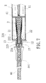
- a double component container mainly consists of a main material tube 1 and a subsidiary material tube 2.
- the main material tube 1 includes a hollow tube 11, a discharge pipe part 12 on a front end thereof, a plurality of positioning ribs 13 disposed projectingly around an inner wall of the discharge pipe part 12, a ring hole 14 formed by the positioning ribs 13 arranged circularly, and an outer threaded part 15 formed on an outer wall of the discharge pipe part 12.
- the subsidiary material tube 2 formed by a plurality of sleeves 21 and a discharge pipe part 22 is mounted in the main material tube 1.
- the diameter of each sleeve 21 is gradually increased and the sleeves 21 are sleeved with one another.
- the discharge pipe part 22 it inserts into the ring hole 14 formed by the positioning ribs 13 of the main material tube 1.
- a connection segment 221 is formed on a rear end of the discharge pipe part 22 so as to sleeve with the adjacent sleeve 21 while a stopping edge 222 is formed on a front side of the connection segment 221 for pressing against the rear end of the positioning ribs 13.
- a step-like locking edge 223 for locking with the front end of the positioning ribs 13 is formed on the discharge pipe part 22.
- a contracted tube opening 224 is formed on a front part of the discharge pipe part 22.
- a plug sleeve 3 includes a receiving slot 31 corresponding to the discharge pipe part 12 on the front end of the main material tube 1.
- An inner threaded part 32 corresponding to the outer threaded part 15 of the discharge pipe part 12 of the main material tube 1 is disposed on a wall of the receiving slot 31 so as to thread with the outer threaded part 15 of the discharge pipe part 12.
- a cell 33 corresponding to the tube opening 224 of the discharge pipe part 22 of the subsidiary material tube 2 is disposed concavely on the bottom of the receiving slot 31.
- the adhesive dispenser 4 can be those disclosed in Taiwanese Pat. App. Pub. No. 540431 -"improved adhesive dispenser", Taiwanese Pat. App. Pub. No. 469879 , Taiwanese Pat. App. Pub. No. 469881 , Taiwanese Pat. App. Pub. No. 121307 , and so on. Those are all an adhesive dispenser with a single push out rod 41 available on the market and the push out rod 41 of the adhesive dispenser 4 presses against rear ends of the main and the subsidiary material tubes 1, 2.
- a filler tube 44 with a spiral stirrer 441 is installed at the discharge pipe parts 12, 22 of the main and the subsidiary material tubes 1, 2. Then the grip 42 of the adhesive dispenser 4 is held by a user's hand and a lever 43 of the adhesive dispenser 4 is pulled so as to make the push out rod 41 connected with the lever 43 move forward to press against the main and the subsidiary material tubes 1, 2. Thus the adhesive and the hardener filled in the main and the subsidiary material tubes 1, 2 are pushed simultaneously by the push out rod 41 and are discharged from the discharge pipe parts 12, 22 of the main and the subsidiary material tubes 1, 2. In the filler tube 44, the adhesive and the hardener are mixed well by the spiral stirrer 441.
- the mixed adhesive with the hardener is pushed out through the front end of the filler tube 44 to coat the positions that need repair such as gaps between bathroom tiles, fish tanks or eaves.
- an adhesive is applied to predrilled holes.
- the adhesive is cured quickly due to the hardener added therein so as to make the embedded steel bars connect with the concrete firmly.
- dirt on the adhesive due to attachment of dust and debris on the adhesive caused by long curing time of the adhesive can be avoided.
- a few strips of adhesive smudges formed on a vertical surface or wall resulted from long curing time can be prevented.
- the double component container of the present invention is applied to a common adhesive dispenser available now on the market. There is no need to buy the adhesive dispenser with special specification. Thus the consumers save their money, reduce their economic burden. Furthermore, without the use of the adhesive dispenser with special specification, the waste caused by less use or discarding is avoided.
- the present invention has a plurality of advantages, such as:
Landscapes
- Engineering & Computer Science (AREA)
- Mechanical Engineering (AREA)
- Tubes (AREA)
- Coating Apparatus (AREA)
- Package Specialized In Special Use (AREA)
- Containers And Packaging Bodies Having A Special Means To Remove Contents (AREA)
- External Artificial Organs (AREA)
- Packages (AREA)
Claims (4)
- Doppelkomponentenbehälter, dadurch gekennzeichnet, dass er umfasst:- ein Hauptmaterialrohr (1), das ein Hohlrohr (11) mit einem ersten Auslaufrohrteil (12) an einem vorderen Ende davon ist, und- ein Nebenmaterialrohr (2), das in dem Hauptmaterialrohr (1) montiert angebracht ist und eine Rohröffnung (224) aufweist, die dem Auslaufrohrteil (12) des Hauptmaterialrohrs (1) entspricht,- dadurch gekennzeichnet, dass das Nebenmaterialrohr (2) eine Mehrzahl von Hülsen (21) aufweist, die ineinander eingesetzt sind, während der Durchmesser der Hülsen (21) stufenweise zunimmt.
- Vorrichtung nach Anspruch 1, dadurch gekennzeichnet, dass eine Mehrzahl von Positionierungsrippen (13) um eine Innenwand des Auslaufrohrteils (12) am vorderen Ende des Hauptmaterialrohrs (1) hervorstehend angeordnet sind, und die Positionierungsrippen (13) ein Ringloch (14) bilden, während das Nebenmaterialrohr (2) ein zweites Auslaufrohrteil (22) aufweist, das in das Ringloch (14), das von den Positionierungsrippen (13) des Hauptmaterialrohrs (1) gebildet ist, eingesteckt ist, und überdies ein Verbindungssegment (221) aufweist, das an einem hinteren Ende des zweiten Auslaufrohrteils (22) gebildet ist, so dass es mit der benachbarten Hülse (21) eine Hülsenverbindung eingeht; eine Anschlagkante (222) ist an einer Vorderseite des Verbindungssegments (221) gebildet, so dass sie gegen das hintere Ende der Positionierungsrippen (13) drückt, und eine stufenartige Verriegelungskante (223) zum Verriegeln mit dem vorderen Ende der Positionierungsrippen (13) ist an dem zweiten Auslaufrohrteil (22) des Nebenmaterialrohrs (2) gebildet; eine Rohröffnung (224) ist an einem vorderen Teil des zweiten Auslaufrohrteils (2) des Nebenmaterialrohrs (2) gebildet.
- Vorrichtung nach Anspruch 2, dadurch gekennzeichnet, dass die Rohröffnung (224) an dem zweiten Auslaufrohrteil (22) des Nebenmaterialrohrs (2) im Verhältnis zum ersten Auslaufrohrteil (12) zusammengezogen ist.
- Vorrichtung nach Anspruch 2, dadurch gekennzeichnet, dass der Doppelkomponentenbehälter überdies eine Abdeckhülse (3) umfasst, die das vordere Ende des Hauptmaterialrohrs (1) und des Nebenmaterialrohrs (2) bedeckt, wobei die Abdeckhülse (3) eine Aufnahmeaussparung (31) aufweist, die dem Auslaufrohrteil (12) an dem vorderen Ende des Hauptmaterialrohrs (1) entspricht, und eine Zelle (33), die der Rohröffnung (224) des zweiten Auslaufrohrteils (22) des Nebenmaterialrohrs (2) entspricht, die konkav an dem Boden der Aufnahmeaussparung ( 31) gebildet ist.
Applications Claiming Priority (1)
| Application Number | Priority Date | Filing Date | Title |
|---|---|---|---|
| TW097149528A TWI346005B (en) | 2008-12-18 | 2008-12-18 | Double fluid container |
Publications (2)
| Publication Number | Publication Date |
|---|---|
| EP2202177A1 EP2202177A1 (de) | 2010-06-30 |
| EP2202177B1 true EP2202177B1 (de) | 2012-03-14 |
Family
ID=41820412
Family Applications (1)
| Application Number | Title | Priority Date | Filing Date |
|---|---|---|---|
| EP09177170A Not-in-force EP2202177B1 (de) | 2008-12-18 | 2009-11-26 | Doppelkomponentenbehälter |
Country Status (12)
| Country | Link |
|---|---|
| US (1) | US20100155424A1 (de) |
| EP (1) | EP2202177B1 (de) |
| JP (1) | JP2010143643A (de) |
| KR (1) | KR20100070986A (de) |
| AT (1) | ATE549271T1 (de) |
| AU (1) | AU2009238355A1 (de) |
| BR (1) | BRPI0905315A2 (de) |
| CA (1) | CA2685614A1 (de) |
| CL (1) | CL2009002185A1 (de) |
| ES (1) | ES2382237T3 (de) |
| SG (1) | SG162662A1 (de) |
| TW (1) | TWI346005B (de) |
Families Citing this family (10)
| Publication number | Priority date | Publication date | Assignee | Title |
|---|---|---|---|---|
| GB0922732D0 (en) * | 2009-12-31 | 2010-02-17 | Kordan Mark A | Improved adaptor |
| CA2891058A1 (en) * | 2012-10-30 | 2014-05-08 | Zachary L. Green | Applicator assemblies and methods for dispensation of composition comprising phosphorescent material |
| DE102018117146A1 (de) | 2018-04-12 | 2019-10-17 | Fischerwerke Gmbh & Co. Kg | Mehrkammerkartusche |
| CN112334119A (zh) | 2018-06-29 | 2021-02-05 | 宝洁公司 | 双相产品 |
| EP3814021A2 (de) * | 2018-06-29 | 2021-05-05 | The Procter & Gamble Company | Spender für zweiphasen-produkte |
| CN112165885B (zh) | 2018-06-29 | 2023-11-07 | 宝洁公司 | 双相产品 |
| JP7208267B2 (ja) | 2018-06-29 | 2023-01-18 | ザ プロクター アンド ギャンブル カンパニー | 二相製品 |
| DE102018117142A1 (de) | 2018-07-16 | 2020-01-16 | Fischerwerke Gmbh & Co. Kg | Mehrkammerkartusche |
| CN113996508A (zh) * | 2020-07-28 | 2022-02-01 | 南京德朔实业有限公司 | 电动工具 |
| GB2618624A (en) * | 2022-05-13 | 2023-11-15 | Fix A Floor Uk Ltd | Micro injection flooring repair apparatus and method |
Family Cites Families (10)
| Publication number | Priority date | Publication date | Assignee | Title |
|---|---|---|---|---|
| US1662857A (en) * | 1925-12-12 | 1928-03-20 | Henry L Heiter | Container |
| DE2939116A1 (de) * | 1979-09-27 | 1981-04-16 | Henkel KGaA, 4000 Düsseldorf | Vorrichtung zum getrennten aufbewahren sowie zum mischen fliessender komponenten |
| US4340154A (en) * | 1980-10-24 | 1982-07-20 | Voplex Corporation | Caulker for dispensing two viscous components |
| US4457641A (en) * | 1981-04-13 | 1984-07-03 | Smith Donald R | Material dispenser apparatus |
| DE3200542A1 (de) * | 1982-01-11 | 1983-07-21 | Teroson Gmbh, 6900 Heidelberg | Verfahren zum entleeren von kartuschenartigen behaeltern sowie behaelter zur durchfuehrung des verfahrens |
| US5310091A (en) * | 1993-05-12 | 1994-05-10 | Tremco, Inc. | Dual product dispenser |
| JPH1191784A (ja) * | 1997-09-22 | 1999-04-06 | Riso Kagaku Corp | 減容化容器 |
| DE19943877B4 (de) * | 1999-09-14 | 2008-08-07 | Alfred Fischbach Kg Kunststoff-Spritzgusswerk | Zweikomponentenkartusche für fließfähige Medien |
| ITMI20021287A1 (it) * | 2002-06-11 | 2003-12-11 | Bossong Spa | Cartuccia per resine sintetiche a piu' componenti in particolare per ancoraggio chimico |
| US7748567B2 (en) * | 2006-03-29 | 2010-07-06 | Nordson Corporation | Single dose dual fluid cartridge for use with hand-held applicators |
-
2008
- 2008-12-18 TW TW097149528A patent/TWI346005B/zh not_active IP Right Cessation
-
2009
- 2009-11-02 US US12/588,893 patent/US20100155424A1/en not_active Abandoned
- 2009-11-09 CA CA2685614A patent/CA2685614A1/en not_active Abandoned
- 2009-11-10 JP JP2009257016A patent/JP2010143643A/ja active Pending
- 2009-11-13 KR KR1020090109757A patent/KR20100070986A/ko not_active Ceased
- 2009-11-17 AU AU2009238355A patent/AU2009238355A1/en not_active Abandoned
- 2009-11-24 SG SG200907813-0A patent/SG162662A1/en unknown
- 2009-11-26 AT AT09177170T patent/ATE549271T1/de active
- 2009-11-26 ES ES09177170T patent/ES2382237T3/es active Active
- 2009-11-26 EP EP09177170A patent/EP2202177B1/de not_active Not-in-force
- 2009-12-09 BR BRPI0905315-8A patent/BRPI0905315A2/pt not_active IP Right Cessation
- 2009-12-17 CL CL2009002185A patent/CL2009002185A1/es unknown
Also Published As
| Publication number | Publication date |
|---|---|
| SG162662A1 (en) | 2010-07-29 |
| US20100155424A1 (en) | 2010-06-24 |
| ES2382237T3 (es) | 2012-06-06 |
| TWI346005B (en) | 2011-08-01 |
| KR20100070986A (ko) | 2010-06-28 |
| AU2009238355A1 (en) | 2010-07-08 |
| CA2685614A1 (en) | 2010-06-18 |
| BRPI0905315A2 (pt) | 2013-07-02 |
| EP2202177A1 (de) | 2010-06-30 |
| TW201023980A (en) | 2010-07-01 |
| JP2010143643A (ja) | 2010-07-01 |
| ATE549271T1 (de) | 2012-03-15 |
| CL2009002185A1 (es) | 2010-10-29 |
Similar Documents
| Publication | Publication Date | Title |
|---|---|---|
| EP2202177B1 (de) | Doppelkomponentenbehälter | |
| US9555928B2 (en) | Cartridge and multicomponent cartridge | |
| EP1634654B1 (de) | Zweiteilige Flüssigkeitspatrone für die Lagerung und Abgabe von Flüssigkeiten in ungleichen Verhältnissen | |
| US5419460A (en) | Container for flowable substances | |
| US3730394A (en) | Putty mixing container for caulking gun-type dispenser | |
| US8985402B2 (en) | Cove base nozzle for dispensing applications | |
| US10105731B2 (en) | Cartridge, method of manufacturing same and multicomponent cartridge | |
| US20090020561A1 (en) | Dispensing Appliance for a Double Syringe | |
| US20060151530A1 (en) | Dual fluid cartridge with reduced fluid waste | |
| US9975139B2 (en) | Cartridge and method for producing a cartridge | |
| US20150174604A1 (en) | Applicator for in Particular Manually Controlled Application of a Light-Curable Composite Material and Arrangement of a Light Source on the Applicator | |
| CN101412010A (zh) | 压出设备 | |
| JP6200909B2 (ja) | 弁体を備えた2液混合吐出器 | |
| WO2006026990A1 (en) | Nozzle for use in connection with the dosing of a material from a container, method and use hereof | |
| US20090152307A1 (en) | Non-cylindrical bead for caulking tube | |
| US20120248058A1 (en) | Cartridge having a plug | |
| EP3251756A1 (de) | Gehäuse und spender | |
| US6737000B2 (en) | Method for mixing, combining and dispensing reactive two component materials using a rotary stop cock | |
| WO1992016707A1 (en) | Injection flange | |
| KR100573429B1 (ko) | 주입식 케미컬 앵커 | |
| KR20200010814A (ko) | 일체형 노즐을 갖는 실리콘건 | |
| KR200393945Y1 (ko) | 이 성분 혼합형 용기 | |
| KR200321452Y1 (ko) | 접착제 용기 | |
| DE8125319U1 (de) | Spendervorrichtung fuer pastenartige Massen | |
| US20150239642A1 (en) | Universal cartridge nozzle and kit |
Legal Events
| Date | Code | Title | Description |
|---|---|---|---|
| PUAI | Public reference made under article 153(3) epc to a published international application that has entered the european phase |
Free format text: ORIGINAL CODE: 0009012 |
|
| AK | Designated contracting states |
Kind code of ref document: A1 Designated state(s): AT BE BG CH CY CZ DE DK EE ES FI FR GB GR HR HU IE IS IT LI LT LU LV MC MK MT NL NO PL PT RO SE SI SK SM TR |
|
| 17P | Request for examination filed |
Effective date: 20100810 |
|
| RIC1 | Information provided on ipc code assigned before grant |
Ipc: B65D 81/32 20060101AFI20110704BHEP |
|
| GRAP | Despatch of communication of intention to grant a patent |
Free format text: ORIGINAL CODE: EPIDOSNIGR1 |
|
| GRAS | Grant fee paid |
Free format text: ORIGINAL CODE: EPIDOSNIGR3 |
|
| GRAA | (expected) grant |
Free format text: ORIGINAL CODE: 0009210 |
|
| AK | Designated contracting states |
Kind code of ref document: B1 Designated state(s): AT BE BG CH CY CZ DE DK EE ES FI FR GB GR HR HU IE IS IT LI LT LU LV MC MK MT NL NO PL PT RO SE SI SK SM TR |
|
| REG | Reference to a national code |
Ref country code: GB Ref legal event code: FG4D |
|
| REG | Reference to a national code |
Ref country code: AT Ref legal event code: REF Ref document number: 549271 Country of ref document: AT Kind code of ref document: T Effective date: 20120315 Ref country code: CH Ref legal event code: EP |
|
| REG | Reference to a national code |
Ref country code: IE Ref legal event code: FG4D |
|
| REG | Reference to a national code |
Ref country code: DE Ref legal event code: R096 Ref document number: 602009005878 Country of ref document: DE Effective date: 20120510 |
|
| REG | Reference to a national code |
Ref country code: ES Ref legal event code: FG2A Ref document number: 2382237 Country of ref document: ES Kind code of ref document: T3 Effective date: 20120606 |
|
| REG | Reference to a national code |
Ref country code: NL Ref legal event code: VDEP Effective date: 20120314 |
|
| PG25 | Lapsed in a contracting state [announced via postgrant information from national office to epo] |
Ref country code: LT Free format text: LAPSE BECAUSE OF FAILURE TO SUBMIT A TRANSLATION OF THE DESCRIPTION OR TO PAY THE FEE WITHIN THE PRESCRIBED TIME-LIMIT Effective date: 20120314 Ref country code: NO Free format text: LAPSE BECAUSE OF FAILURE TO SUBMIT A TRANSLATION OF THE DESCRIPTION OR TO PAY THE FEE WITHIN THE PRESCRIBED TIME-LIMIT Effective date: 20120614 Ref country code: HR Free format text: LAPSE BECAUSE OF FAILURE TO SUBMIT A TRANSLATION OF THE DESCRIPTION OR TO PAY THE FEE WITHIN THE PRESCRIBED TIME-LIMIT Effective date: 20120314 |
|
| LTIE | Lt: invalidation of european patent or patent extension |
Effective date: 20120314 |
|
| PG25 | Lapsed in a contracting state [announced via postgrant information from national office to epo] |
Ref country code: LV Free format text: LAPSE BECAUSE OF FAILURE TO SUBMIT A TRANSLATION OF THE DESCRIPTION OR TO PAY THE FEE WITHIN THE PRESCRIBED TIME-LIMIT Effective date: 20120314 Ref country code: FI Free format text: LAPSE BECAUSE OF FAILURE TO SUBMIT A TRANSLATION OF THE DESCRIPTION OR TO PAY THE FEE WITHIN THE PRESCRIBED TIME-LIMIT Effective date: 20120314 Ref country code: GR Free format text: LAPSE BECAUSE OF FAILURE TO SUBMIT A TRANSLATION OF THE DESCRIPTION OR TO PAY THE FEE WITHIN THE PRESCRIBED TIME-LIMIT Effective date: 20120615 |
|
| REG | Reference to a national code |
Ref country code: AT Ref legal event code: MK05 Ref document number: 549271 Country of ref document: AT Kind code of ref document: T Effective date: 20120314 |
|
| PG25 | Lapsed in a contracting state [announced via postgrant information from national office to epo] |
Ref country code: CY Free format text: LAPSE BECAUSE OF FAILURE TO SUBMIT A TRANSLATION OF THE DESCRIPTION OR TO PAY THE FEE WITHIN THE PRESCRIBED TIME-LIMIT Effective date: 20120314 |
|
| PGFP | Annual fee paid to national office [announced via postgrant information from national office to epo] |
Ref country code: IT Payment date: 20120630 Year of fee payment: 4 |
|
| PG25 | Lapsed in a contracting state [announced via postgrant information from national office to epo] |
Ref country code: RO Free format text: LAPSE BECAUSE OF FAILURE TO SUBMIT A TRANSLATION OF THE DESCRIPTION OR TO PAY THE FEE WITHIN THE PRESCRIBED TIME-LIMIT Effective date: 20120314 Ref country code: SI Free format text: LAPSE BECAUSE OF FAILURE TO SUBMIT A TRANSLATION OF THE DESCRIPTION OR TO PAY THE FEE WITHIN THE PRESCRIBED TIME-LIMIT Effective date: 20120314 Ref country code: PL Free format text: LAPSE BECAUSE OF FAILURE TO SUBMIT A TRANSLATION OF THE DESCRIPTION OR TO PAY THE FEE WITHIN THE PRESCRIBED TIME-LIMIT Effective date: 20120314 Ref country code: SE Free format text: LAPSE BECAUSE OF FAILURE TO SUBMIT A TRANSLATION OF THE DESCRIPTION OR TO PAY THE FEE WITHIN THE PRESCRIBED TIME-LIMIT Effective date: 20120314 Ref country code: BE Free format text: LAPSE BECAUSE OF FAILURE TO SUBMIT A TRANSLATION OF THE DESCRIPTION OR TO PAY THE FEE WITHIN THE PRESCRIBED TIME-LIMIT Effective date: 20120314 Ref country code: IS Free format text: LAPSE BECAUSE OF FAILURE TO SUBMIT A TRANSLATION OF THE DESCRIPTION OR TO PAY THE FEE WITHIN THE PRESCRIBED TIME-LIMIT Effective date: 20120714 Ref country code: EE Free format text: LAPSE BECAUSE OF FAILURE TO SUBMIT A TRANSLATION OF THE DESCRIPTION OR TO PAY THE FEE WITHIN THE PRESCRIBED TIME-LIMIT Effective date: 20120314 Ref country code: CZ Free format text: LAPSE BECAUSE OF FAILURE TO SUBMIT A TRANSLATION OF THE DESCRIPTION OR TO PAY THE FEE WITHIN THE PRESCRIBED TIME-LIMIT Effective date: 20120314 |
|
| PG25 | Lapsed in a contracting state [announced via postgrant information from national office to epo] |
Ref country code: PT Free format text: LAPSE BECAUSE OF FAILURE TO SUBMIT A TRANSLATION OF THE DESCRIPTION OR TO PAY THE FEE WITHIN THE PRESCRIBED TIME-LIMIT Effective date: 20120716 Ref country code: SK Free format text: LAPSE BECAUSE OF FAILURE TO SUBMIT A TRANSLATION OF THE DESCRIPTION OR TO PAY THE FEE WITHIN THE PRESCRIBED TIME-LIMIT Effective date: 20120314 |
|
| PLBE | No opposition filed within time limit |
Free format text: ORIGINAL CODE: 0009261 |
|
| STAA | Information on the status of an ep patent application or granted ep patent |
Free format text: STATUS: NO OPPOSITION FILED WITHIN TIME LIMIT |
|
| PG25 | Lapsed in a contracting state [announced via postgrant information from national office to epo] |
Ref country code: NL Free format text: LAPSE BECAUSE OF FAILURE TO SUBMIT A TRANSLATION OF THE DESCRIPTION OR TO PAY THE FEE WITHIN THE PRESCRIBED TIME-LIMIT Effective date: 20120314 Ref country code: DK Free format text: LAPSE BECAUSE OF FAILURE TO SUBMIT A TRANSLATION OF THE DESCRIPTION OR TO PAY THE FEE WITHIN THE PRESCRIBED TIME-LIMIT Effective date: 20120314 Ref country code: AT Free format text: LAPSE BECAUSE OF FAILURE TO SUBMIT A TRANSLATION OF THE DESCRIPTION OR TO PAY THE FEE WITHIN THE PRESCRIBED TIME-LIMIT Effective date: 20120314 |
|
| PGFP | Annual fee paid to national office [announced via postgrant information from national office to epo] |
Ref country code: DE Payment date: 20121109 Year of fee payment: 4 |
|
| 26N | No opposition filed |
Effective date: 20121217 |
|
| PGFP | Annual fee paid to national office [announced via postgrant information from national office to epo] |
Ref country code: ES Payment date: 20121114 Year of fee payment: 4 |
|
| REG | Reference to a national code |
Ref country code: DE Ref legal event code: R097 Ref document number: 602009005878 Country of ref document: DE Effective date: 20121217 |
|
| REG | Reference to a national code |
Ref country code: DE Ref legal event code: R082 Ref document number: 602009005878 Country of ref document: DE Representative=s name: LANGPATENT ANWALTSKANZLEI IP LAW FIRM, DE |
|
| PG25 | Lapsed in a contracting state [announced via postgrant information from national office to epo] |
Ref country code: BG Free format text: LAPSE BECAUSE OF FAILURE TO SUBMIT A TRANSLATION OF THE DESCRIPTION OR TO PAY THE FEE WITHIN THE PRESCRIBED TIME-LIMIT Effective date: 20120614 |
|
| REG | Reference to a national code |
Ref country code: FR Ref legal event code: ST Effective date: 20130731 |
|
| REG | Reference to a national code |
Ref country code: IE Ref legal event code: MM4A |
|
| PG25 | Lapsed in a contracting state [announced via postgrant information from national office to epo] |
Ref country code: IE Free format text: LAPSE BECAUSE OF NON-PAYMENT OF DUE FEES Effective date: 20121126 |
|
| PG25 | Lapsed in a contracting state [announced via postgrant information from national office to epo] |
Ref country code: FR Free format text: LAPSE BECAUSE OF NON-PAYMENT OF DUE FEES Effective date: 20121130 Ref country code: MT Free format text: LAPSE BECAUSE OF FAILURE TO SUBMIT A TRANSLATION OF THE DESCRIPTION OR TO PAY THE FEE WITHIN THE PRESCRIBED TIME-LIMIT Effective date: 20120314 |
|
| PG25 | Lapsed in a contracting state [announced via postgrant information from national office to epo] |
Ref country code: TR Free format text: LAPSE BECAUSE OF FAILURE TO SUBMIT A TRANSLATION OF THE DESCRIPTION OR TO PAY THE FEE WITHIN THE PRESCRIBED TIME-LIMIT Effective date: 20120314 Ref country code: MC Free format text: LAPSE BECAUSE OF NON-PAYMENT OF DUE FEES Effective date: 20121130 |
|
| PG25 | Lapsed in a contracting state [announced via postgrant information from national office to epo] |
Ref country code: LU Free format text: LAPSE BECAUSE OF NON-PAYMENT OF DUE FEES Effective date: 20121126 Ref country code: SM Free format text: LAPSE BECAUSE OF FAILURE TO SUBMIT A TRANSLATION OF THE DESCRIPTION OR TO PAY THE FEE WITHIN THE PRESCRIBED TIME-LIMIT Effective date: 20120314 |
|
| REG | Reference to a national code |
Ref country code: CH Ref legal event code: PL |
|
| GBPC | Gb: european patent ceased through non-payment of renewal fee |
Effective date: 20131126 |
|
| PG25 | Lapsed in a contracting state [announced via postgrant information from national office to epo] |
Ref country code: CH Free format text: LAPSE BECAUSE OF NON-PAYMENT OF DUE FEES Effective date: 20131130 Ref country code: LI Free format text: LAPSE BECAUSE OF NON-PAYMENT OF DUE FEES Effective date: 20131130 Ref country code: HU Free format text: LAPSE BECAUSE OF FAILURE TO SUBMIT A TRANSLATION OF THE DESCRIPTION OR TO PAY THE FEE WITHIN THE PRESCRIBED TIME-LIMIT Effective date: 20091126 |
|
| REG | Reference to a national code |
Ref country code: DE Ref legal event code: R119 Ref document number: 602009005878 Country of ref document: DE Effective date: 20140603 |
|
| PG25 | Lapsed in a contracting state [announced via postgrant information from national office to epo] |
Ref country code: DE Free format text: LAPSE BECAUSE OF NON-PAYMENT OF DUE FEES Effective date: 20140603 Ref country code: IT Free format text: LAPSE BECAUSE OF NON-PAYMENT OF DUE FEES Effective date: 20131126 |
|
| PG25 | Lapsed in a contracting state [announced via postgrant information from national office to epo] |
Ref country code: GB Free format text: LAPSE BECAUSE OF NON-PAYMENT OF DUE FEES Effective date: 20131126 |
|
| REG | Reference to a national code |
Ref country code: ES Ref legal event code: FD2A Effective date: 20150327 |
|
| PG25 | Lapsed in a contracting state [announced via postgrant information from national office to epo] |
Ref country code: ES Free format text: LAPSE BECAUSE OF NON-PAYMENT OF DUE FEES Effective date: 20131127 |
|
| PG25 | Lapsed in a contracting state [announced via postgrant information from national office to epo] |
Ref country code: MK Free format text: LAPSE BECAUSE OF FAILURE TO SUBMIT A TRANSLATION OF THE DESCRIPTION OR TO PAY THE FEE WITHIN THE PRESCRIBED TIME-LIMIT Effective date: 20120314 |