EP2202437A2 - Rohrkupplungsanordnung und ein Schutzring dafür - Google Patents
Rohrkupplungsanordnung und ein Schutzring dafür Download PDFInfo
- Publication number
- EP2202437A2 EP2202437A2 EP10160197A EP10160197A EP2202437A2 EP 2202437 A2 EP2202437 A2 EP 2202437A2 EP 10160197 A EP10160197 A EP 10160197A EP 10160197 A EP10160197 A EP 10160197A EP 2202437 A2 EP2202437 A2 EP 2202437A2
- Authority
- EP
- European Patent Office
- Prior art keywords
- protective ring
- coupling
- ring
- tubulars
- energizing
- Prior art date
- Legal status (The legal status is an assumption and is not a legal conclusion. Google has not performed a legal analysis and makes no representation as to the accuracy of the status listed.)
- Granted
Links
Images




Classifications
-
- F—MECHANICAL ENGINEERING; LIGHTING; HEATING; WEAPONS; BLASTING
- F16—ENGINEERING ELEMENTS AND UNITS; GENERAL MEASURES FOR PRODUCING AND MAINTAINING EFFECTIVE FUNCTIONING OF MACHINES OR INSTALLATIONS; THERMAL INSULATION IN GENERAL
- F16L—PIPES; JOINTS OR FITTINGS FOR PIPES; SUPPORTS FOR PIPES, CABLES OR PROTECTIVE TUBING; MEANS FOR THERMAL INSULATION IN GENERAL
- F16L15/00—Screw-threaded joints; Forms of screw-threads for such joints
- F16L15/001—Screw-threaded joints; Forms of screw-threads for such joints with conical threads
-
- F—MECHANICAL ENGINEERING; LIGHTING; HEATING; WEAPONS; BLASTING
- F16—ENGINEERING ELEMENTS AND UNITS; GENERAL MEASURES FOR PRODUCING AND MAINTAINING EFFECTIVE FUNCTIONING OF MACHINES OR INSTALLATIONS; THERMAL INSULATION IN GENERAL
- F16L—PIPES; JOINTS OR FITTINGS FOR PIPES; SUPPORTS FOR PIPES, CABLES OR PROTECTIVE TUBING; MEANS FOR THERMAL INSULATION IN GENERAL
- F16L58/00—Protection of pipes or pipe fittings against corrosion or incrustation
- F16L58/18—Protection of pipes or pipe fittings against corrosion or incrustation specially adapted for pipe fittings
- F16L58/182—Protection of pipes or pipe fittings against corrosion or incrustation specially adapted for pipe fittings for screw-threaded joints
Definitions
- the present invention relates to a protective ring or gasket for use in a coupling assembly, to a coupling assembly comprising the protective ring, and to a method of coupling tubulars together using the coupling assembly.
- Certain typical multiple walled pipe e.g. a lined steel pipe
- the inner wall is a liner tube made of a corrosion resistant material that serves as a conductor for the corrosive fluid, and an outer wall or pipe that is designed to provide strength to withstand the internal pressures of the corrosive fluid, as well as external forces such as external pressure, mechanical loading, etc.
- the length of such double walled pipes due to conditions to which the pipes are subjected on site.
- each joint of pipe is usually about 7.32-13.41m (24-44 feet) long while the tubing or casing string itself may be thousands of feet long. Accordingly, and as is well known in making up such tubing or casing string, successive joints of tubing/casing are connected together using a coupling (or coupling assembly) until the desired length of string is achieved. Similarly in pipelines successive pieces of pipe are joined by couplings.
- the coupling comprises an annular body for placement between and to which two tubulars may be connected.
- the annular body has a thread on its interior surface for receiving the thread on the end of the each of the tubulars.
- An annular gasket is positioned substantially centrally within and co-axial with the annular body. In use, each tubular comes into abutment with one side of the annular gasket as it is screwed into the annular body.
- An example of such a coupling assembly is shown in US-A-5 470 111 .
- a protective ring for use in a coupling assembly, the coupling assembly comprising a coupling body of generally cylindrical shape with a channel therethrough, each end of the coupling body having a thread for threaded mating with a tubular so that the coupling assembly may provide a connection between two tubulars
- the protective ring comprising a ring body for positioning adjacent an interior wall of the coupling body between the two ends thereof and located for contact by the two tubulars, the ring body being generally cylindrical and having a ring channel therethrough, characterised in that the protective ring comprises an energizing member, the arrangement being such that, in use, upon compression of the protective ring between the two tubulars the energizing member urges the ring body against the interior wall of the coupling body whereby corrosive material is inhibited from contact therewith.
- the protective ring may be sized and configured for use in coupling oil and gas tubulars for example.
- the energizing member is disposed within the ring body.
- the energizing member extends around the ring body and is substantially co-axial therewith, whereby the ring body is inhibited from bowing inwardly during compression between the two tubulars.
- the protective ring further comprises a plurality of energizing members.
- each energizing member comprises a material having a hardness, and wherein the hardness of at least one energizing member is less than the hardness of at least one other energizing member, the arrangement being such that, in use, the at least one energizing member of lesser hardness begins to change shape under compression before the at least one other energizing member.
- the protective ring further comprises an opening in the ring body, the arrangement being such that, in use, under compression between the two tubulars, the opening begins to close facilitating a change in shape of the ring body substantially without a change in volume thereof.
- the at least one opening is of sufficient size that, in use, under compression between the two tubulars the ring body is inhibited from significant expansion into a flow path defined by the coupling assembly and the two tubulars.
- the opening is associated with the energizing member.
- the opening extends from the exterior of the ring body to the energizing member.
- the protective ring further comprises a plurality of openings, each opening corresponding to a respective energizing member.
- the plurality of openings is on an exterior of the ring body and at least one of the plurality of openings is on an interior of the ring body.
- the plurality of openings comprises a first opening, a second opening, and a third opening and each of both the first opening and the third opening extend from an interior of the protective ring to a corresponding energizing member, and the second opening extends from an exterior of the protective ring to a corresponding energizing member.
- the opening is sized for accommodating manufacturing length tolerances of the two tubulars when the protective ring is compressed therebetween.
- the ring body comprises a projecting edge adapted to be trapped between the interior wall of the coupling member and a tapered portion of one of the two tubulars.
- the at least one energizing member comprises a resilient elastomeric material.
- the ring body comprises a compressible anti-corrosive material.
- the protective ring comprises at least one concave area extending around at least a part of the circumference of the ring body.
- the at least one concave area extends around substantially the whole of the circumference of the ring body.
- the at least one concave area comprises a plurality of spaced-apart concave areas.
- at least one concave area is on an exterior of the ring body and at least one concave area is on an interior of the ring body.
- the at least one concave area on the exterior comprises three spaced-apart areas, and the at least one concave area on the interior is two spaced-apart areas.
- the protective ring further comprises a plurality of the energizing members in the protective ring, the three spaced-apart areas on the ring body's exterior comprising a first area, a second area, and a third area, a first energizing member of the plurality of energizing members located between the first area and the second area, a second energizing member of the plurality of energizing members located between the second area and the third area, the two spaced-apart areas on the ring body's interior comprising a fourth area and a fifth area, a third energizing member of the plurality of energizing members located between the fourth area and the fifth area, the protective ring having a first end and a second end, a fourth energizing member of the plurality of energizing members located between the first end and the fourth area, and a fifth energizing member of the plurality of energizing members located between the second end and the fifth area
- a protective ring for use in a coupling assembly, the coupling assembly comprising a coupling body of generally cylindrical shape with a channel therethrough, each end of the coupling body having a thread for threaded mating with a tubular so that the coupling assembly may provide a connection between two tubulars, the protective ring comprising a ring body for positioning adjacent an interior wall of the coupling body between the two ends thereof and located for contact by the two tubulars, the ring body being generally cylindrical and having a ring channel therethrough, characterised in that the protective ring comprises at least one concave area extending around at least a part of the circumference of the ring body.
- the protective ring may comprise any of the protective ring features set out in claims 1 to 22.
- a coupling assembly for a coupling together two tubulars, which coupling assembly comprises a coupling body of generally cylindrical shape with a channel therethrough, each end of the coupling body having a thread for threaded mating with a tubular so that the coupling assembly may provide a connection between two tubulars, and a protective ring as aforesaid.
- the coupling assembly may be supplied as a kit of parts for assembly at point of use.
- the present invention discloses, in certain embodiments, a protective ring for use in a coupling member, the coupling member having a coupling body with an interior wall, the coupling body being generally cylindrical and having a channel therethrough, the coupling body with two spaced-apart ends, each end threaded for threaded mating with a tubular so that the coupling member is connectible to two tubulars, the protective ring having: a protective ring body positionable adjacent an interior wall of a coupling body of a coupling member between the two spaced-apart ends of the coupling body and located for contact by two tubulars coupled together by the coupling member; the protective ring body being generally cylindrical and having a protective ring channel therethrough; the protective ring body having a volume; and at least one energizing member within the protective ring.
- the present invention discloses, in certain embodiments, a protective ring for use in a coupling member for coupling together two tubulars, the coupling member with a coupling body, the coupling body being generally cylindrical and having a channel therethrough, the coupling body with two spaced-apart ends, each end threaded for threaded mating with a tubular so that the coupling member is connectible to two tubulars, the coupling body having an interior wall, the protective ring having: a protective ring body positionable adjacent an interior wall of a coupling body of a coupling member between the two spaced-apart ends of the coupling body and located for contact by an end of each of two tubulars; the protective ring body being generally cylindrical and having a protective ring channel therethrough; the protective ring body having a circumference; the protective ring body having a volume; and at least one concave area on a surface of the protective ring.
- the present invention discloses, in certain embodiments, a tubular coupling assembly with a coupling member and an interior protective ring that has at least one inner energizing member which, upon compression, forces the body of the coupling member against the interior wall of the coupling thereby inhibiting corrosive material from contacting the coupling's interior wall or, in the event some corrosive material does enter this area, the interior protective ring is held against the coupling's interior wall so that the corrosive material, once present, may not exit this area, thus preventing a continuous flow of corrosive material into and out of this area.
- such a protective ring has two or more energizing members; and in one particular aspect such a protective ring has three spaced-apart energizing members located in recesses adjacent openings in the protective ring that provide for controlled compression of the protective ring and holding of the protective ring in position with respect to the coupling's interior wall. In another aspect there are five energizing members, two positioned in the protective ring adjacent an inner wall of a coupling member and three positioned in an inner wall of the protective ring.
- Any protective ring according to the present invention may have one, two, three, four, five or more concave areas on the protective ring, on the protective ring's exterior and/or on the protective ring's interior to enhance directed controlled energizing of the protective ring into contact with a coupling member.
- a protective ring has three concave portions on the protective ring's exterior and two concave portions on the protective ring's interior.
- such a protective ring (with one - five or more concave areas) may have one - five or more energizing members.
- an energizing member is located between two concave areas.
- a coupling assembly 10 having a coupling member 20 which is a generally cylindrical hollow member with interiorly threaded spaced-apart ends 22, 24 and an interior wall 26.
- Two tubulars 32, 34 are threadedly connected to respective ends 22, 24 of the coupling member.
- a protective ring 40 (shown schematically) which is any protective ring according to the present invention.
- the tubulars 32, 34 have a liner 36 which may be any known tubular liner.
- the protective ring 40 has one, two, three, four, five or more (one shown) energizing member 42.
- a recess, slit, or opening 44 leads from an exterior of the protective ring 40 to the energizing member(s) 42 which allow movement (e.g. axial movement of the protective ring) when compressive forces are applied to the protective ring without a change in volume of the protective ring but with controlled change in shape of the protective ring.
- Fig. 1B is a top (or bottom) view of one embodiments 40a of a protective ring 40.
- Fig. 1C is a top (or bottom) view of one embodiment 42a of a protective ring 42.
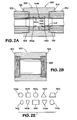
- the protective rings and energizing members of Figs. 2A, 2E and 3A are, similarly, items which are generally circular.
- a coupling assembly 100 has a protective ring 140 according to the present invention held in compression between the pin ends 136, 138 of the pipes 132, 134.
- Each pin end 136, 138 is threadedly secured in a respective end 122, 124 of a coupling member 120.
- the protective ring 140 has three spaced-apart openings 144a, 144b, and 144c, each of which extends interiorly from an exterior of the protective ring 140 and extends to an interior space which contains an energizing member 142a, 142b, 142c, respectively.
- Any energizing member in any embodiment of the present invention may have any suitable cross-section shape, including but not limited to, those shown in Fig. 2E (shapes as follows: 142e, circular; 142f, square; 142g, hexagonal; 142h, triangular; 142i, trapezoidal; 142j, oval; 142k, teardrop; 1421, rectangular; 142m, teardrop; 142p, barrel).
- Each pin end 136, 138 has an outer end bevel or taper 136a, 138a, respectively. Edge portions 146, 147 of the protective ring 140 are squeezed between an interior wall 126 of the coupling member 120 and the bevelled pin ends, thus assisting in securing the protective ring 140 in place adjacent the interior wall 126 of the coupling member 120.
- all energizing members of a protective ring (any disclosed herein) according to the present invention to be of the same or of different hardness.
- the two energizing members 142a, 142c are of the same hardness and the energizing member 142b is of a material harder than the material of the energizing members 142a, 142c.
- the energizing members 142a, 142c are made of a resilient elastomeric material, e.g., but not limited to, nitrile or butile; in certain aspects the members 142a, 142c with a hardness of about 70 durometer and the member 142b with a hardness of about 90 durometer.
- Any protective ring according to the present invention may have energizing members located further interiorly than other energizing members and of a hardness less than the other energizing members (e.g. other energizing members at an exterior wall of a protective ring).
- the protective ring 140 extends around the entire inner circumference of the coupling member 120 and the energizing members 142a, 142b, and 142c (and their corresponding openings 144a, 144b, 144c) extend around (and within) the entire circumference of the protective ring 140.
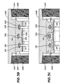
- Fig. 3A shows a protective ring 200 according to the present invention (e.g. usable in the coupling assemblies of Figs. 1A and 2A ).
- a body 202 of the protective ring 200 is made of compressible anti-corrosive material, e.g. elastomeric resilient material, polytetrafluoroethylene (“PTFE”), or a combination of elastomer and PTFE.
- PTFE polytetrafluoroethylene
- Energizing members 231, 232, 233 are located within the interior spaces 221, 222, 223, respectively.
- the protective ring 200 has outer edges or "teeth" 204, 205.
- the openings 211, 212, 213, the spaces 221, 222, 223 and the energizing members 231, 232, 233 extend around the entire generally cylindrical body 202 (which is like the protective rings 40 and 140 in general hollow cylindrical shape although only part of the protective ring 200 is shown in Fig. 3A ).
- the body 202 has a circumferential indentation 206 or concave area therearound.
- the protective ring 200 is positioned adjacent and installed inside a coupling member 240 (shown partially - shaped generally cylindrically as the coupling members 20 and 120 described above) having internally threaded ends 242, 244 for threadedly mating with externally threaded ends (e.g. the ends 252, 254 of pipes 262, 264, Fig. 3E ).
- a coupling member 240 shown partially - shaped generally cylindrically as the coupling members 20 and 120 described above
- internally threaded ends 242, 244 for threadedly mating with externally threaded ends (e.g. the ends 252, 254 of pipes 262, 264, Fig. 3E ).
- the protective ring 200 is being compressed (indicated by arrows C1, C2), e.g. by pin ends of two tubulars to be connected together by the coupling 240. Since energizing members 231 and 233 are not as hard as the energizing member 232, the energizing members 231 and 233 move under compression before the energizing member 232, thus the protective ring 200 begins to move outwardly (toward the coupling member 240 as shown in Fig. 3C ). The openings 211 and 213 begin to restrict and close. Then the opening 212 begins to restrict and close.
- the openings 211 - 213 provide space so that the protective ring 200 does not significantly expand into the flow path of the coupling member 240.
- the indentation 206 also facilitates the outward movement (toward the coupling member interior wall) of the protective ring 200 and provides an area or a void for protective ring material to flow to when the protective ring is compressing.
- Fig. 3D illustrates the protective ring 200 fully compressed with the openings 211 - 213 closed and the energizing members 231 - 233 compressed (the members 231 - 233 have changed shape).
- the protective ring 200 has been forced against an interior wall 246 of the coupling member and, due to the openings 211 - 213, the indentation 206, and/or the entrapment of the two teeth 204, 205, the protective ring 200 has been biased outwardly and prevented from bowing inwardly so that the protective ring 200 is pressed up against the interior wall 246 along the length of the protective ring 200.
- the energizing members 231 - 233 are pushing the protective ring 200 against the coupling's interior wall.
- the edges or teeth 204, 205 of the protective ring 200 have been trapped between tapered ends of the tubulars 262, 264 and part of the interior wall 246 of the coupling member 240, thus facilitating maintenance of the protective ring 200 in position to protect the interior wall 246.
- oil country tubular goods are made according to certain length tolerances, e.g. one-eighth inch plus or minus.
- this manufacturing tolerance can be accommodated.
- each opening e.g. 211 - 213
- 0.66 inches for a total of about 0.200 inches (actually 0.198 inches) and the energizing members themselves e.g.
- members 231 - 233) can be squeezed a total of another 0.050 inches, a total of about 0.250 inches of compression is available, i.e., an amount equal to about the manufactuprotective ring tolerance of one-eighth inch plus or minus (a total of one-fourth inch).
- Fig. 4A shows a protective ring 300 according to the present invention useful in protecting a coupling member (e.g. a coupling member as in Figs. 1A , 2A , 3B or 3E ).
- the protective ring 300 (only half is shown) has a body 302 with a first end 304 and a second end 306. Each end, optionally, has a projecting edge or tooth 314, 316, respectively which extends around the entire circumference of its respective circular end.
- a plurality of concave areas extend around the protective ring's circumference areas 321, 322, 323 on the protective ring's exterior surface and areas 324, 325 on the protective ring's interior surface.
- the energizing members are, in one aspect, omitted. Any one, some, or all of the recesses 341 - 345 may be omitted.
- edges or teeth 314, 316 can be trapped as described above for the edges 204, 205.
- each energizing member 343, 344, 345 can be located opposite a concave area 321, 322, 323 (along with other forces) respectively, and, upon energizing force the concave areas outwardly.
- Fig. 4B illustrates a protective ring 350, like the protective ring 300, but with only one energizing member 354 on an interior surface of a protective ring body 352.
- the energizing member 354 is in a recess 356 which is positioned between two concave areas 351. These concave areas 351 are on the body's exterior surface and the body 352 has two end edges or teeth 353, 359.
- Fig. 4C shows a protective ring 360, like the protective ring 350, but without the concave areas 351.
- a body 362 has three concave areas 363 on the body's exterior surface.
- any energizing member or members disclosed herein can be added to the protective ring 360.
- Fig. 4D shows a protective ring 370, like the protective ring 350, but without energizing members.
- a body 372 has two concave areas 373 on the body's interior surface.
- ends of the body 362 have edges 374.
- any energizing member or members disclosed herein can be added to the protective ring 370.
- Fig. 5A shows a protective ring 400 according to the present invention which is a generally cylindrical hollow member (only half shown).
- the protective ring 400 has a body 402 with a concave area 404 on its exterior surface.
- the concave area 404 extends around the body of the protective ring.
- the concave area(s) may be intermittent, a single pocket, or a series of spaced-apart distinct pockets. Ends of the body 402, optionally, have edges 406.
- Fig. 5B shows a protective ring 410 according to the present invention which is like the protective ring 410 but which includes a recess 412 with an energizing member 416 therein.
- the protective ring 410 has a body 418 with a concave area 415 and with optional end edges 419.
- Fig. 5C shows a protective ring 430 according to the present invention with a body 432 having optional end edges 433.
- a concave area 434 is on the body's exterior surface.
- Fig. 5D shows a protective ring 440 according to the present invention with a body 442.
- the body 442 has a concave area 443 on its exterior and a recess 444 on its interior.
- the energizing member may extend only so far as the area or pocket(s) or it may still extend uninterrupted around the protective ring's circumference.
- Fig. 6A illustrates a protective ring 600 with a plurality of spaced-apart concave areas 604 in a body 602.
- energizing members 606 are adjacent each pocket.
- an energizing member 608 can extend adjacent all pockets 604a in a body 602a.
- the protective ring and coupling assembly of the present invention may find application in various fields including, but not limited to, coupling any clad or lined tubulars including oil and gas well tubing and casing, piping in chemical and other plants, oil and gas pipelines, etc.
- the present invention therefore, provides in at least certain, but not necessarily all, embodiments, a protective ring, the protective ring having: a protective ring body positionable adjacent an interior wall of a coupling body of a coupling member between two spaced-apart ends of the coupling body and located for contact by two tubulars coupled together by the coupling member; the protective ring body being generally cylindrical and having a protective ring channel therethrough; the protective ring body having a volume; and at least one energizing member within the protective ring.
- Such a protective ring may have one or some, in any possible combination, of the following: at least one opening leading through the protective ring to the at least one energizing member; the at least one energizing member is a plurality of spaced-apart energizing members; the at least one opening is a plurality of openings, one opening corresponding to each of a plurality of energizing members; the plurality of openings is a first opening, a second opening, and a third opening and each of both the first opening and the third opening extend from an interior of the protective ring to a corresponding energizing member, and the second opening extends from an exterior of the protective ring to a corresponding energizing member; the two tubulars each have a tapered portion and the protective ring body has a first end and a second end, and two spaced-apart outer edges, one at the first end of the protective ring body and one at the second end of the protective ring body, and each outer edge trappable
- a protective ring for use in a coupling member for coupling together two tubulars, the coupling member with a coupling body, the coupling body being generally cylindrical and having a channel therethrough, the coupling body with two spaced-apart ends, each end threaded for threaded mating with a tubular so that the coupling member is connectible to two tubulars, the coupling body having an interior wall, the protective ring including: a protective ring body positionable adjacent an interior wall of a coupling body of a coupling member between the two spaced-apart ends of the coupling body and located for contact by two tubulars by abutment by an end of each tubular, the protective ring body being generally cylindrical and having a protective ring channel therethrough, the protective ring body having a volume, a plurality of spaced-apart energizing members within the protective ring, the spaced-apart energizing members comprising at least
- the present invention therefore, provides in at least certain, but not necessarily all, embodiments, a system for a coupling together two tubulars, the system including: a coupling member with a coupling body, the coupling body being generally cylindrical and having a channel therethrough, the coupling body with two spaced-apart ends, each end threaded for threaded mating with a tubular so that the coupling member is connectible to two tubulars, the coupling body having an interior wall; a protective ring body positioned adjacent the interior wall of the coupling body between the two spaced-apart ends of the coupling body and located for contact by the two tubulars by abutment by an end of each tubular, the protective ring being generally cylindrical and having a protective ring channel therethrough, the protective ring having a volume, and at least one energizing member within the protective ring.
- the present invention therefore, provides in at least certain, but not necessarily all, embodiments, a protective ring for use in a coupling member for coupling together two tubulars, the coupling member with a coupling body, the coupling body being generally cylindrical and having a channel therethrough, the coupling body with two spaced-apart ends, each end threaded for threaded mating with a tubular so that the coupling member is connectible to two tubulars, the coupling body having an interior wall, the protective ring including: a protective ring body positionable adjacent an interior wall of a coupling body of a coupling member between the two spaced-apart ends of the coupling body and located for contact by an end of each of two tubulars, the protective ring body being generally cylindrical and having a protective ring channel therethrough, the protective ring body having a circumference, the protective ring body having a volume, and at least one concave area on a surface of the protective ring.
- Such a protective ring may have one or some, in any possible combination, of the following: the at least one concave area extends around the protective ring's circumference; one or a plurality of spaced-apart energizing members in the protective ring; the or each energizing member extending around the protective ring's circumference; the at least one concave area is a plurality of spaced-apart concave areas; each of the plurality of spaced-apart concave areas extends around the protective ring's circumference; and/or the protective ring has an exterior and an interior, at least one concave area on the protective ring's exterior, and at least one concave area on the protective ring's interior; the at least one concave area on the protective ring's exterior is three spaced-apart areas, and the at least one concave area on the protective ring's interior is two spaced-apart areas; a plurality of energizing members in the protective ring, the three
- the present invention therefore, provides in at least certain, but not necessarily all, embodiments, a system for coupling together two tubulars, the system including: a coupling member with a coupling body, the coupling body being generally cylindrical and having a channel therethrough, the coupling body with two spaced-apart ends, each end threaded for threaded mating with a tubular so that the coupling member is connectible to two tubulars, the coupling body having an interior wall; a protective ring positioned adjacent the interior wall of the central portion of the coupling body between the two spaced-apart ends of the coupling body and located for contact by an end of each of the two tubulars, the protective ring being generally cylindrical and having a protective ring channel therethrough, the protective ring having a circumference, the protective ring having a volume; and at least one concave area on a surface of the protective ring.
- the present invention therefore, provides in at least certain, but not necessarily all, embodiments, a method for coupling together two tubulars comprising a first tubular and a second tubular, the first tubular having an end with exterior threading, the second tubular having an end with exterior threading, the method including: threadedly engaging each threaded end of the each of the two tubulars with an end of two spaced-apart ends of a coupling assembly, the coupling assembly as any disclosed herein; a protective ring positioned adjacent the interior wall of the central portion of the coupling body between the two spaced-apart ends of the coupling body and located for contact by the two tubulars by abutment by an end of each tubular, the protective ring being generally cylindrical and having a protective ring channel therethrough, the protective ring having a volume, at least one energizing member within the protective ring, an end of each tubular contacting the protective ring and compressing the protective ring, and said compression energizing the at least one energ
- Such a method may include one or some, in any possible combination, of the following: the at least one energizing member is a plurality of spaced-apart energizing members, the at least one opening is a plurality of openings, one opening corresponding to each energizing member, at least one opening extends from an interior of the protective ring to a corresponding energizing member, and at least one opening extends from an exterior of the protective ring to a corresponding energizing member; the protective ring has two spaced-apart outer edges, one at the first end of the protective ring and one at the second end of the protective ring, and each outer edge trappable between an interior portion of the coupling member and tapered portions of the two tubulars, the method including trapping each outer edge between the interior portion of the coupling member and a tapered portion of one of the two tubulars; the plurality of spaced-apart energizing members comprise at least a first energizing member and a second
Landscapes
- General Engineering & Computer Science (AREA)
- Engineering & Computer Science (AREA)
- Mechanical Engineering (AREA)
- Quick-Acting Or Multi-Walled Pipe Joints (AREA)
- Mutual Connection Of Rods And Tubes (AREA)
- Protection Of Pipes Against Damage, Friction, And Corrosion (AREA)
- Flanged Joints, Insulating Joints, And Other Joints (AREA)
- Joints With Sleeves (AREA)
- Non-Disconnectible Joints And Screw-Threaded Joints (AREA)
- Mechanical Operated Clutches (AREA)
- Earth Drilling (AREA)
- Laying Of Electric Cables Or Lines Outside (AREA)
- Pens And Brushes (AREA)
- Joints That Cut Off Fluids, And Hose Joints (AREA)
- Buffer Packaging (AREA)
Applications Claiming Priority (3)
| Application Number | Priority Date | Filing Date | Title |
|---|---|---|---|
| US11/528,702 US20080073905A1 (en) | 2006-09-27 | 2006-09-27 | Pipe coupling system |
| US11/540,939 US7731246B2 (en) | 2006-09-29 | 2006-09-29 | Pipe coupling system |
| EP07733561.0A EP2069672B1 (de) | 2006-09-27 | 2007-03-21 | Kupplungsanordnung und schutzring dafür |
Related Parent Applications (2)
| Application Number | Title | Priority Date | Filing Date |
|---|---|---|---|
| EP07733561.0 Division | 2007-03-21 | ||
| EP07733561.0A Division-Into EP2069672B1 (de) | 2006-09-27 | 2007-03-21 | Kupplungsanordnung und schutzring dafür |
Publications (3)
| Publication Number | Publication Date |
|---|---|
| EP2202437A2 true EP2202437A2 (de) | 2010-06-30 |
| EP2202437A3 EP2202437A3 (de) | 2010-08-04 |
| EP2202437B1 EP2202437B1 (de) | 2011-11-09 |
Family
ID=38068946
Family Applications (3)
| Application Number | Title | Priority Date | Filing Date |
|---|---|---|---|
| EP10160197A Active EP2202437B1 (de) | 2006-09-27 | 2007-03-21 | Rohrkupplungsanordnung und ein Schutzring dafür |
| EP07733561.0A Active EP2069672B1 (de) | 2006-09-27 | 2007-03-21 | Kupplungsanordnung und schutzring dafür |
| EP10160204.3A Active EP2202438B1 (de) | 2006-09-27 | 2007-03-21 | Rohrkupplungsanordnung mit einem Schutzring |
Family Applications After (2)
| Application Number | Title | Priority Date | Filing Date |
|---|---|---|---|
| EP07733561.0A Active EP2069672B1 (de) | 2006-09-27 | 2007-03-21 | Kupplungsanordnung und schutzring dafür |
| EP10160204.3A Active EP2202438B1 (de) | 2006-09-27 | 2007-03-21 | Rohrkupplungsanordnung mit einem Schutzring |
Country Status (12)
| Country | Link |
|---|---|
| EP (3) | EP2202437B1 (de) |
| CN (1) | CN102506248B (de) |
| AT (1) | ATE533001T1 (de) |
| AU (1) | AU2007301689B2 (de) |
| BR (3) | BR122018015577B1 (de) |
| CA (1) | CA2664737C (de) |
| EA (2) | EA019186B1 (de) |
| MX (1) | MX2009003262A (de) |
| NO (2) | NO340193B1 (de) |
| PL (2) | PL2202438T3 (de) |
| SG (2) | SG175560A1 (de) |
| WO (1) | WO2008038034A1 (de) |
Families Citing this family (4)
| Publication number | Priority date | Publication date | Assignee | Title |
|---|---|---|---|---|
| BR122018015577B1 (pt) | 2006-09-27 | 2019-10-01 | National Oilwell Varco, L.P. | Anel protetor para uso em uma montagem de acoplamento e método para acoplar dois tubulares |
| GB2496882A (en) * | 2011-11-24 | 2013-05-29 | Plumb Partners Group Ltd | Pipe connector for connecting two axial pipe ends |
| GB2502958B (en) * | 2012-06-11 | 2019-04-24 | Halliburton Energy Services Inc | Improvements relating to core barrel outer tubes |
| GB2524522B (en) | 2014-03-25 | 2020-03-25 | Nat Oilwell Varco Lp | Coupling assembly and protective ring therefor |
Citations (2)
| Publication number | Priority date | Publication date | Assignee | Title |
|---|---|---|---|---|
| US5470111A (en) | 1994-08-12 | 1995-11-28 | Tuboscope Vetco International, Inc. | Plastic coating thread and coupling assembly |
| EP2069672A1 (de) | 2006-09-27 | 2009-06-17 | National Oilwell Varco, L.P. | Kupplungsanordnung und schutzring dafür |
Family Cites Families (15)
| Publication number | Priority date | Publication date | Assignee | Title |
|---|---|---|---|---|
| US1889868A (en) * | 1930-07-21 | 1932-12-06 | Gustavus A Montgomery | Double box rotary tool joint |
| US1889869A (en) * | 1930-08-02 | 1932-12-06 | Gustavus A Montgomery | Tube coupling |
| US2487241A (en) * | 1947-01-16 | 1949-11-08 | Lewis D Hilton | Thread seal and buffer gasket for pipe couplings |
| GB641125A (en) * | 1948-02-09 | 1950-08-02 | Chiksan Co | Improvements in or relating to swivel joints for pipes and tubes |
| US2805872A (en) * | 1954-12-03 | 1957-09-10 | Rice Engineering And Operating | Lined pipe coupling with internally flush gasket |
| DE2048569C2 (de) * | 1970-10-02 | 1983-05-19 | Kempchen & Co Gmbh, 4200 Oberhausen | Dichtung |
| GB2032033B (en) * | 1978-10-04 | 1983-02-02 | Oakes Ltd | Joining of pipes |
| US4875713A (en) * | 1985-09-24 | 1989-10-24 | Kenneth J. Carstensen | Internally coated tubular system |
| US4679831A (en) * | 1986-06-13 | 1987-07-14 | Kielminski William P | Pipe coupling connection sealing apparatus |
| US4856828A (en) * | 1987-12-08 | 1989-08-15 | Tuboscope Inc. | Coupling assembly for tubular articles |
| CA2148498A1 (en) * | 1992-11-13 | 1994-05-26 | Michael Roy Chambers | Corrosion resistant connection for use with tubular members |
| DK1197686T3 (da) * | 1999-06-29 | 2004-11-01 | Ampo S Coop | Höjelastisk tætning til procesudstyr for flydende naturgas |
| US6179002B1 (en) * | 2000-01-06 | 2001-01-30 | National Coupling Company, Inc. | Hydraulic coupling with pressure-energized dovetail seal |
| US7575256B2 (en) * | 2003-08-06 | 2009-08-18 | National Coupling Company, Inc. | Bore liner for undersea hydraulic coupling |
| US7303194B2 (en) * | 2003-10-20 | 2007-12-04 | National Coupling Company, Inc. | Seal retainer with pressure energized metal seal members for undersea hydraulic coupling |
-
2007
- 2007-03-21 BR BR122018015577-9A patent/BR122018015577B1/pt active IP Right Grant
- 2007-03-21 WO PCT/GB2007/050136 patent/WO2008038034A1/en not_active Ceased
- 2007-03-21 PL PL10160204T patent/PL2202438T3/pl unknown
- 2007-03-21 AU AU2007301689A patent/AU2007301689B2/en active Active
- 2007-03-21 EP EP10160197A patent/EP2202437B1/de active Active
- 2007-03-21 EA EA201100477A patent/EA019186B1/ru not_active IP Right Cessation
- 2007-03-21 SG SG2011069598A patent/SG175560A1/en unknown
- 2007-03-21 CN CN201110326064.7A patent/CN102506248B/zh active Active
- 2007-03-21 PL PL07733561T patent/PL2069672T3/pl unknown
- 2007-03-21 AT AT10160197T patent/ATE533001T1/de active
- 2007-03-21 EP EP07733561.0A patent/EP2069672B1/de active Active
- 2007-03-21 EP EP10160204.3A patent/EP2202438B1/de active Active
- 2007-03-21 CA CA2664737A patent/CA2664737C/en active Active
- 2007-03-21 BR BRPI0715283-3A patent/BRPI0715283B1/pt active IP Right Grant
- 2007-03-21 MX MX2009003262A patent/MX2009003262A/es active IP Right Grant
- 2007-03-21 EA EA200970321A patent/EA018172B1/ru not_active IP Right Cessation
- 2007-03-21 BR BR122018015575-2A patent/BR122018015575B1/pt active IP Right Grant
- 2007-03-21 SG SG2011069614A patent/SG174839A1/en unknown
-
2009
- 2009-03-31 NO NO20091310A patent/NO340193B1/no unknown
-
2017
- 2017-01-18 NO NO20170081A patent/NO349346B1/no unknown
Patent Citations (2)
| Publication number | Priority date | Publication date | Assignee | Title |
|---|---|---|---|---|
| US5470111A (en) | 1994-08-12 | 1995-11-28 | Tuboscope Vetco International, Inc. | Plastic coating thread and coupling assembly |
| EP2069672A1 (de) | 2006-09-27 | 2009-06-17 | National Oilwell Varco, L.P. | Kupplungsanordnung und schutzring dafür |
Also Published As
| Publication number | Publication date |
|---|---|
| BR122018015575B1 (pt) | 2019-10-01 |
| EP2202438A2 (de) | 2010-06-30 |
| CN102506248A (zh) | 2012-06-20 |
| PL2069672T3 (pl) | 2014-08-29 |
| EA019186B1 (ru) | 2014-01-30 |
| CA2664737C (en) | 2013-07-30 |
| EA018172B1 (ru) | 2013-06-28 |
| EP2069672B1 (de) | 2014-03-12 |
| EP2069672A1 (de) | 2009-06-17 |
| BRPI0715283B1 (pt) | 2018-09-18 |
| SG174839A1 (en) | 2011-10-28 |
| MX2009003262A (es) | 2009-04-08 |
| EP2202438A3 (de) | 2010-08-04 |
| NO20170081A1 (no) | 2009-06-23 |
| CN102506248B (zh) | 2014-12-24 |
| AU2007301689B2 (en) | 2012-11-29 |
| EP2202437A3 (de) | 2010-08-04 |
| PL2202438T3 (pl) | 2014-08-29 |
| EA201100477A1 (ru) | 2011-10-31 |
| BRPI0715283A2 (pt) | 2013-01-01 |
| EA200970321A1 (ru) | 2009-10-30 |
| NO340193B1 (no) | 2017-03-20 |
| EP2202437B1 (de) | 2011-11-09 |
| NO349346B1 (no) | 2025-12-15 |
| ATE533001T1 (de) | 2011-11-15 |
| AU2007301689A1 (en) | 2008-04-03 |
| NO20091310L (no) | 2009-06-23 |
| EP2202438B1 (de) | 2014-03-05 |
| BR122018015577B1 (pt) | 2019-10-01 |
| CA2664737A1 (en) | 2008-04-03 |
| WO2008038034A1 (en) | 2008-04-03 |
| SG175560A1 (en) | 2011-11-28 |
Similar Documents
| Publication | Publication Date | Title |
|---|---|---|
| US10344897B2 (en) | Pipe coupling system and method | |
| US4735444A (en) | Pipe coupling for well casing | |
| US4915426A (en) | Pipe coupling for well casing | |
| CA2691104C (en) | A method and apparatus for inhibiting corrosion in strings of tubulars | |
| BRPI0416408B1 (pt) | Realization, by plastic expansion, of a tubular seal with overlaying (s) of local (is) and initial (is) | |
| US20060267343A1 (en) | Pipe coupling | |
| CA2664737C (en) | Coupling assembly and protective ring therefor | |
| CN101529145A (zh) | 联接组件及其保护环 | |
| US5988692A (en) | Metal to plastic pipe transition fitting | |
| CA2711468C (en) | High pressure pipe liner coupling assembly and method | |
| AU2012241155B2 (en) | Coupling assembly and protective ring therefor | |
| EP3532761B1 (de) | Rohrverbindung | |
| RU2752226C2 (ru) | Фитинг высокого давления | |
| GB2390882A (en) | A pipe coupling with expandable gripper ring | |
| WO2013101852A1 (en) | High torque threaded pipe connection | |
| JPH0552482U (ja) | 流体輸送管の端末構造 |
Legal Events
| Date | Code | Title | Description |
|---|---|---|---|
| PUAI | Public reference made under article 153(3) epc to a published international application that has entered the european phase |
Free format text: ORIGINAL CODE: 0009012 |
|
| AC | Divisional application: reference to earlier application |
Ref document number: 2069672 Country of ref document: EP Kind code of ref document: P |
|
| AK | Designated contracting states |
Kind code of ref document: A2 Designated state(s): AT BE BG CH CY CZ DE DK EE ES FI FR GB GR HU IE IS IT LI LT LU LV MC MT NL PL PT RO SE SI SK TR |
|
| PUAL | Search report despatched |
Free format text: ORIGINAL CODE: 0009013 |
|
| AK | Designated contracting states |
Kind code of ref document: A3 Designated state(s): AT BE BG CH CY CZ DE DK EE ES FI FR GB GR HU IE IS IT LI LT LU LV MC MT NL PL PT RO SE SI SK TR |
|
| 17P | Request for examination filed |
Effective date: 20101216 |
|
| GRAP | Despatch of communication of intention to grant a patent |
Free format text: ORIGINAL CODE: EPIDOSNIGR1 |
|
| RIC1 | Information provided on ipc code assigned before grant |
Ipc: F16L 58/18 20060101ALI20110606BHEP Ipc: F16L 15/04 20060101AFI20110606BHEP |
|
| GRAS | Grant fee paid |
Free format text: ORIGINAL CODE: EPIDOSNIGR3 |
|
| GRAA | (expected) grant |
Free format text: ORIGINAL CODE: 0009210 |
|
| AC | Divisional application: reference to earlier application |
Ref document number: 2069672 Country of ref document: EP Kind code of ref document: P |
|
| AK | Designated contracting states |
Kind code of ref document: B1 Designated state(s): AT BE BG CH CY CZ DE DK EE ES FI FR GB GR HU IE IS IT LI LT LU LV MC MT NL PL PT RO SE SI SK TR |
|
| REG | Reference to a national code |
Ref country code: GB Ref legal event code: FG4D |
|
| REG | Reference to a national code |
Ref country code: CH Ref legal event code: EP |
|
| REG | Reference to a national code |
Ref country code: IE Ref legal event code: FG4D |
|
| REG | Reference to a national code |
Ref country code: DE Ref legal event code: R096 Ref document number: 602007018691 Country of ref document: DE Effective date: 20120119 |
|
| REG | Reference to a national code |
Ref country code: NL Ref legal event code: T3 |
|
| LTIE | Lt: invalidation of european patent or patent extension |
Effective date: 20111109 |
|
| PG25 | Lapsed in a contracting state [announced via postgrant information from national office to epo] |
Ref country code: IS Free format text: LAPSE BECAUSE OF FAILURE TO SUBMIT A TRANSLATION OF THE DESCRIPTION OR TO PAY THE FEE WITHIN THE PRESCRIBED TIME-LIMIT Effective date: 20120309 Ref country code: LT Free format text: LAPSE BECAUSE OF FAILURE TO SUBMIT A TRANSLATION OF THE DESCRIPTION OR TO PAY THE FEE WITHIN THE PRESCRIBED TIME-LIMIT Effective date: 20111109 |
|
| PG25 | Lapsed in a contracting state [announced via postgrant information from national office to epo] |
Ref country code: GR Free format text: LAPSE BECAUSE OF FAILURE TO SUBMIT A TRANSLATION OF THE DESCRIPTION OR TO PAY THE FEE WITHIN THE PRESCRIBED TIME-LIMIT Effective date: 20120210 Ref country code: BE Free format text: LAPSE BECAUSE OF FAILURE TO SUBMIT A TRANSLATION OF THE DESCRIPTION OR TO PAY THE FEE WITHIN THE PRESCRIBED TIME-LIMIT Effective date: 20111109 Ref country code: SI Free format text: LAPSE BECAUSE OF FAILURE TO SUBMIT A TRANSLATION OF THE DESCRIPTION OR TO PAY THE FEE WITHIN THE PRESCRIBED TIME-LIMIT Effective date: 20111109 Ref country code: PL Free format text: LAPSE BECAUSE OF FAILURE TO SUBMIT A TRANSLATION OF THE DESCRIPTION OR TO PAY THE FEE WITHIN THE PRESCRIBED TIME-LIMIT Effective date: 20111109 Ref country code: SE Free format text: LAPSE BECAUSE OF FAILURE TO SUBMIT A TRANSLATION OF THE DESCRIPTION OR TO PAY THE FEE WITHIN THE PRESCRIBED TIME-LIMIT Effective date: 20111109 Ref country code: PT Free format text: LAPSE BECAUSE OF FAILURE TO SUBMIT A TRANSLATION OF THE DESCRIPTION OR TO PAY THE FEE WITHIN THE PRESCRIBED TIME-LIMIT Effective date: 20120309 Ref country code: LV Free format text: LAPSE BECAUSE OF FAILURE TO SUBMIT A TRANSLATION OF THE DESCRIPTION OR TO PAY THE FEE WITHIN THE PRESCRIBED TIME-LIMIT Effective date: 20111109 |
|
| PG25 | Lapsed in a contracting state [announced via postgrant information from national office to epo] |
Ref country code: CY Free format text: LAPSE BECAUSE OF FAILURE TO SUBMIT A TRANSLATION OF THE DESCRIPTION OR TO PAY THE FEE WITHIN THE PRESCRIBED TIME-LIMIT Effective date: 20111109 |
|
| PG25 | Lapsed in a contracting state [announced via postgrant information from national office to epo] |
Ref country code: EE Free format text: LAPSE BECAUSE OF FAILURE TO SUBMIT A TRANSLATION OF THE DESCRIPTION OR TO PAY THE FEE WITHIN THE PRESCRIBED TIME-LIMIT Effective date: 20111109 Ref country code: DK Free format text: LAPSE BECAUSE OF FAILURE TO SUBMIT A TRANSLATION OF THE DESCRIPTION OR TO PAY THE FEE WITHIN THE PRESCRIBED TIME-LIMIT Effective date: 20111109 Ref country code: CZ Free format text: LAPSE BECAUSE OF FAILURE TO SUBMIT A TRANSLATION OF THE DESCRIPTION OR TO PAY THE FEE WITHIN THE PRESCRIBED TIME-LIMIT Effective date: 20111109 Ref country code: BG Free format text: LAPSE BECAUSE OF FAILURE TO SUBMIT A TRANSLATION OF THE DESCRIPTION OR TO PAY THE FEE WITHIN THE PRESCRIBED TIME-LIMIT Effective date: 20120209 Ref country code: SK Free format text: LAPSE BECAUSE OF FAILURE TO SUBMIT A TRANSLATION OF THE DESCRIPTION OR TO PAY THE FEE WITHIN THE PRESCRIBED TIME-LIMIT Effective date: 20111109 |
|
| PG25 | Lapsed in a contracting state [announced via postgrant information from national office to epo] |
Ref country code: IT Free format text: LAPSE BECAUSE OF FAILURE TO SUBMIT A TRANSLATION OF THE DESCRIPTION OR TO PAY THE FEE WITHIN THE PRESCRIBED TIME-LIMIT Effective date: 20111109 Ref country code: RO Free format text: LAPSE BECAUSE OF FAILURE TO SUBMIT A TRANSLATION OF THE DESCRIPTION OR TO PAY THE FEE WITHIN THE PRESCRIBED TIME-LIMIT Effective date: 20111109 |
|
| PLBE | No opposition filed within time limit |
Free format text: ORIGINAL CODE: 0009261 |
|
| STAA | Information on the status of an ep patent application or granted ep patent |
Free format text: STATUS: NO OPPOSITION FILED WITHIN TIME LIMIT |
|
| REG | Reference to a national code |
Ref country code: AT Ref legal event code: MK05 Ref document number: 533001 Country of ref document: AT Kind code of ref document: T Effective date: 20111109 |
|
| 26N | No opposition filed |
Effective date: 20120810 |
|
| PG25 | Lapsed in a contracting state [announced via postgrant information from national office to epo] |
Ref country code: MC Free format text: LAPSE BECAUSE OF NON-PAYMENT OF DUE FEES Effective date: 20120331 |
|
| REG | Reference to a national code |
Ref country code: CH Ref legal event code: PL |
|
| REG | Reference to a national code |
Ref country code: DE Ref legal event code: R097 Ref document number: 602007018691 Country of ref document: DE Effective date: 20120810 |
|
| REG | Reference to a national code |
Ref country code: FR Ref legal event code: ST Effective date: 20121130 |
|
| REG | Reference to a national code |
Ref country code: IE Ref legal event code: MM4A |
|
| PG25 | Lapsed in a contracting state [announced via postgrant information from national office to epo] |
Ref country code: CH Free format text: LAPSE BECAUSE OF NON-PAYMENT OF DUE FEES Effective date: 20120331 Ref country code: FR Free format text: LAPSE BECAUSE OF NON-PAYMENT OF DUE FEES Effective date: 20120402 Ref country code: AT Free format text: LAPSE BECAUSE OF FAILURE TO SUBMIT A TRANSLATION OF THE DESCRIPTION OR TO PAY THE FEE WITHIN THE PRESCRIBED TIME-LIMIT Effective date: 20111109 Ref country code: IE Free format text: LAPSE BECAUSE OF NON-PAYMENT OF DUE FEES Effective date: 20120321 Ref country code: LI Free format text: LAPSE BECAUSE OF NON-PAYMENT OF DUE FEES Effective date: 20120331 |
|
| PG25 | Lapsed in a contracting state [announced via postgrant information from national office to epo] |
Ref country code: ES Free format text: LAPSE BECAUSE OF FAILURE TO SUBMIT A TRANSLATION OF THE DESCRIPTION OR TO PAY THE FEE WITHIN THE PRESCRIBED TIME-LIMIT Effective date: 20120220 |
|
| PG25 | Lapsed in a contracting state [announced via postgrant information from national office to epo] |
Ref country code: FI Free format text: LAPSE BECAUSE OF FAILURE TO SUBMIT A TRANSLATION OF THE DESCRIPTION OR TO PAY THE FEE WITHIN THE PRESCRIBED TIME-LIMIT Effective date: 20111109 |
|
| PG25 | Lapsed in a contracting state [announced via postgrant information from national office to epo] |
Ref country code: MT Free format text: LAPSE BECAUSE OF FAILURE TO SUBMIT A TRANSLATION OF THE DESCRIPTION OR TO PAY THE FEE WITHIN THE PRESCRIBED TIME-LIMIT Effective date: 20111109 |
|
| PG25 | Lapsed in a contracting state [announced via postgrant information from national office to epo] |
Ref country code: TR Free format text: LAPSE BECAUSE OF FAILURE TO SUBMIT A TRANSLATION OF THE DESCRIPTION OR TO PAY THE FEE WITHIN THE PRESCRIBED TIME-LIMIT Effective date: 20111109 |
|
| PG25 | Lapsed in a contracting state [announced via postgrant information from national office to epo] |
Ref country code: LU Free format text: LAPSE BECAUSE OF NON-PAYMENT OF DUE FEES Effective date: 20120321 |
|
| PG25 | Lapsed in a contracting state [announced via postgrant information from national office to epo] |
Ref country code: HU Free format text: LAPSE BECAUSE OF FAILURE TO SUBMIT A TRANSLATION OF THE DESCRIPTION OR TO PAY THE FEE WITHIN THE PRESCRIBED TIME-LIMIT Effective date: 20070321 |
|
| PGFP | Annual fee paid to national office [announced via postgrant information from national office to epo] |
Ref country code: NL Payment date: 20260106 Year of fee payment: 20 |
|
| PGFP | Annual fee paid to national office [announced via postgrant information from national office to epo] |
Ref country code: GB Payment date: 20260106 Year of fee payment: 20 |
|
| PGFP | Annual fee paid to national office [announced via postgrant information from national office to epo] |
Ref country code: DE Payment date: 20260102 Year of fee payment: 20 |