EP2202464A2 - Champ de cuisson - Google Patents
Champ de cuisson Download PDFInfo
- Publication number
- EP2202464A2 EP2202464A2 EP09180786A EP09180786A EP2202464A2 EP 2202464 A2 EP2202464 A2 EP 2202464A2 EP 09180786 A EP09180786 A EP 09180786A EP 09180786 A EP09180786 A EP 09180786A EP 2202464 A2 EP2202464 A2 EP 2202464A2
- Authority
- EP
- European Patent Office
- Prior art keywords
- hob
- support member
- upper support
- lower support
- stiffening element
- Prior art date
- Legal status (The legal status is an assumption and is not a legal conclusion. Google has not performed a legal analysis and makes no representation as to the accuracy of the status listed.)
- Withdrawn
Links
- 238000010411 cooking Methods 0.000 title claims abstract description 15
- 230000000087 stabilizing effect Effects 0.000 claims abstract description 10
- 230000003014 reinforcing effect Effects 0.000 abstract description 4
- 238000009434 installation Methods 0.000 description 3
- 238000004519 manufacturing process Methods 0.000 description 3
- 230000000284 resting effect Effects 0.000 description 3
- 241000237983 Trochidae Species 0.000 description 1
- 238000005452 bending Methods 0.000 description 1
- 230000007423 decrease Effects 0.000 description 1
- 230000003247 decreasing effect Effects 0.000 description 1
- 238000011161 development Methods 0.000 description 1
- 230000018109 developmental process Effects 0.000 description 1
- 239000000463 material Substances 0.000 description 1
- 239000002184 metal Substances 0.000 description 1
- 239000002994 raw material Substances 0.000 description 1
- 238000011084 recovery Methods 0.000 description 1
- 230000006641 stabilisation Effects 0.000 description 1
- 238000011105 stabilization Methods 0.000 description 1
- 239000003351 stiffener Substances 0.000 description 1
- 230000001960 triggered effect Effects 0.000 description 1
- 230000000007 visual effect Effects 0.000 description 1
- 239000002023 wood Substances 0.000 description 1
Images






Classifications
-
- F—MECHANICAL ENGINEERING; LIGHTING; HEATING; WEAPONS; BLASTING
- F24—HEATING; RANGES; VENTILATING
- F24C—DOMESTIC STOVES OR RANGES ; DETAILS OF DOMESTIC STOVES OR RANGES, OF GENERAL APPLICATION
- F24C15/00—Details
- F24C15/10—Tops, e.g. hot plates; Rings
- F24C15/102—Tops, e.g. hot plates; Rings electrically heated
-
- F—MECHANICAL ENGINEERING; LIGHTING; HEATING; WEAPONS; BLASTING
- F24—HEATING; RANGES; VENTILATING
- F24C—DOMESTIC STOVES OR RANGES ; DETAILS OF DOMESTIC STOVES OR RANGES, OF GENERAL APPLICATION
- F24C15/00—Details
- F24C15/10—Tops, e.g. hot plates; Rings
Definitions
- the delay or the lack of flatness of the upper support member on the lower support member may be visible to the naked eye and then affects the appearance of the hob. Furthermore, in gas hobs, the performance of the hob can be affected if occur due to the lack of flatness of the upper support element air pressure surges in the hob. Such air pressure surges can, for example be triggered by closing the doors of base units of the hob and accidentally extinguish the gas flame.
- a gas hob 100 ' which has a rail 10', on which the upper support member 40 is supported (see. FIG. 12 ).
- This rail 10 ' is fixed to the bottom 70 of the lower support member 50.
- the width of the rail 10 ' corresponds approximately to the width of the region of the juxtaposed controls 30 for operating the cooking zones. More specifically, the rail 10 'is mounted behind the controls 30 centered in the hob 100'.
- the rail stiffens the hob 100 'in a central region of the hob located near the front wall 52.
- the upper support element 40 is fastened to its front side by means of screws 92 'on the lower support element 50 (cf. FIG. 13 ).
- the edges of the upper support member are connected by means of elbows with the lower support member to achieve a low installation depth while maintaining high rigidity of the mounting tray.
- these angle pieces stabilize the hob only in its edge region.
- the present invention has the object, a cooking field of the type mentioned in such a way that the hob, in particular its the operating side of the hob front area facing, a particularly high flexural rigidity having.
- the present invention is based on arranging in the hob at least one stiffening element, which extends from one of the edge walls of the lower support member to its opposite edge wall, preferably from one side wall to the other side wall.
- the stiffening element supports the upper support element so that it does not sag.
- the present hob is separate from the prior art, in which the rail is arranged only in a central region of the hob (see. FIG. 12 ), Due to the advantage that over the entire width or the entire length of the hob, a flat position of the upper support member on the lower support member and thus a low installation depth is made possible.
- the hob according to the invention is reliably protected over its entire width or length, both during its manufacture and during its use from deformation. This offers the advantage that, in contrast to the prior art, no screws have to be attached to the user-visible upper side in order to achieve a correct flatness of the upper support element on the lower support element.
- the stiffening element may have any geometry. Preferably, it is a plate or a rail or a strip, for example a bent plate or a bent rail or a bent bar, such as with a square profile.
- the stiffening element is preferably arranged in the region of the operating elements for operating the cooking zones.
- the stiffening element may be directly on the lower support element, in particular on at least one of the vertical edge walls or at the bottom of the lower support element, support or stand on it.
- the stiffening element attached to at least one of the vertical edge walls or at the bottom of the lower support member, for example, welded, bolted, riveted or glued be.
- the stiffening element rests on a piece of furniture adjacent to the lower support element and rests on it.
- the piece of furniture may for example be a worktop, which is preferably formed from a low thermal conductivity material, such as wood or plastic.
- the stiffening element can be welded to the piece of furniture, screwed, riveted or glued.
- a resting on the piece of furniture stiffener protects the hob particularly reliable against temperature-induced deformation, since the furniture, unlike the usually formed of metal lower support element does not change its shape in heat or cold.
- no tolerances for the installation of the hob in the kitchen unit need to be taken into account.
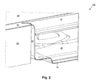
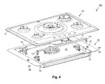
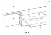
- FIGS. 1 to 11 illustrated four embodiments explained in more detail.
- FIGS. 1 to 3 show a first embodiment of a hob 100 according to the invention, namely a gas hob.
- This cooktop 100 has an upper support element 40, namely a cooktop cover plate or a so-called top sheet, and a lower support element 50, namely a cooktop tray or a so-called bottom sheet.
- a trained for supporting the upper support member 40 flange 60 is arranged on the upper support member 40 facing edge of the vertically extending edge walls 52, 54, 56, 58 of the lower support member 50.
- This flange 60 is received in the region of a pocket-like AufEnglishung 42 of the upper support member 40, whereby the upper support member 40 is connected to the lower support member 50.
- a rail or bar 10 extends from a side wall 56 of the lower support member 50 to the opposite side wall 58. This rail 10 is located with their respective ends on the flange 60. Since the rail 10 is concealed in the hob 102, it does not disturb the visual appearance of the hob 102.
- the rail 10 is shaped like a strip, so that the upper support element 40 can be supported well on the rail 10.
- FIGS. 4 and 5 A second exemplary embodiment of a hob 102 according to the present invention is shown, which for stiffening the upper support element 40 has a rail 12 extending from one side wall 56 to the other side wall 58 of the lower support element 50.
- This rail 12 differs from that in the FIGS. 1 to 3 illustrated rail 10 in that it has at its respective ends vertically extending in the direction of the bottom 70 of the lower support member 50 side walls 12v.
- These side walls 12v may be supported on the bottom 70 of the lower support member 50 or, as in FIGS FIGS. 4 and 5 shown, only with the side walls 56, 58 of the lower support member 50 are in contact.
- the rail 12 whose side walls 12v are connected by screws with the side walls 56, 58 of the lower support member.
- FIGS. 6 to 8 illustrated third embodiment of a hob 104 according to the present invention
- the upper support member 40 stiffened by a rail 14, which is supported on the lower support member 50.
- This rail 14 has vertically extending legs 14v, which are supported on the bottom 70 of the lower support member 50.
- the upper support member 40 is stiffened by a rail 16 which is supported on the countertop 80.
- the flange 60 of the lower support member 50 recess 62, in which the rail 16 is disposed at least partially. More specifically, the rail 16 has vertically extending feet 16v at its respective ends, which pass through the recess 62 and rest on the arranged under the flange 60 worktop 80. Since the rail 16 rests on the countertop 80, the hob 104 does not distort even with extreme, caused by cooking temperature fluctuations.
Landscapes
- Engineering & Computer Science (AREA)
- Chemical & Material Sciences (AREA)
- Combustion & Propulsion (AREA)
- Mechanical Engineering (AREA)
- General Engineering & Computer Science (AREA)
- Baking, Grill, Roasting (AREA)
- Combinations Of Kitchen Furniture (AREA)
Applications Claiming Priority (1)
| Application Number | Priority Date | Filing Date | Title |
|---|---|---|---|
| ES200900076A ES2375036B1 (es) | 2008-12-29 | 2008-12-29 | Placa de cocción. |
Publications (2)
| Publication Number | Publication Date |
|---|---|
| EP2202464A2 true EP2202464A2 (fr) | 2010-06-30 |
| EP2202464A3 EP2202464A3 (fr) | 2017-07-12 |
Family
ID=42115769
Family Applications (1)
| Application Number | Title | Priority Date | Filing Date |
|---|---|---|---|
| EP09180786.7A Withdrawn EP2202464A3 (fr) | 2008-12-29 | 2009-12-28 | Champ de cuisson |
Country Status (2)
| Country | Link |
|---|---|
| EP (1) | EP2202464A3 (fr) |
| ES (1) | ES2375036B1 (fr) |
Cited By (5)
| Publication number | Priority date | Publication date | Assignee | Title |
|---|---|---|---|---|
| WO2015198173A1 (fr) | 2014-06-25 | 2015-12-30 | BSH Hausgeräte GmbH | Foyer de cuisson au gaz et plaque de cuisson |
| EP3012535A1 (fr) * | 2014-10-24 | 2016-04-27 | BSH Hausgeräte GmbH | Plaque de recouvrement pour une table de cuisson, plaque de cuisson et procede de fabrication d'une telle table de cuisson |
| EP3023701A3 (fr) * | 2014-10-21 | 2016-06-29 | BSH Electrodomésticos España, S.A. | Dispositif de plaque de cuisson |
| WO2025095873A1 (fr) * | 2023-11-01 | 2025-05-08 | Mamur Teknoloji Sistemleri San. A.S. | Plaque de cuisson dotée d'un élément de renforcement de feuille de support de base |
| EP4399454A4 (fr) * | 2021-09-08 | 2025-05-28 | Mamur Teknoloji Sistemleri San. A.S. | Plaque de cuisson avec élément de renforcement d'une plaque de base |
Citations (2)
| Publication number | Priority date | Publication date | Assignee | Title |
|---|---|---|---|---|
| DE1454333A1 (de) | 1962-12-14 | 1969-02-20 | Siemens Elektrogeraete Gmbh | Einbauherdmulde |
| DE102005026212A1 (de) | 2005-06-07 | 2006-12-14 | BSH Bosch und Siemens Hausgeräte GmbH | Kochmulde |
Family Cites Families (8)
| Publication number | Priority date | Publication date | Assignee | Title |
|---|---|---|---|---|
| GB748614A (en) * | 1953-07-18 | 1956-05-09 | Simplex Electric Co Ltd | Improvements relating to cooking stoves |
| US3051817A (en) * | 1960-01-28 | 1962-08-28 | Gen Motors Corp | Domestic appliance |
| US4032750A (en) * | 1976-03-26 | 1977-06-28 | General Electric Company | Flat plate heating unit with foil heating means |
| US5568804A (en) * | 1992-10-23 | 1996-10-29 | Canadian Gas Research Institute | Sealed combustion range |
| US6410892B1 (en) * | 2001-06-19 | 2002-06-25 | Bsh Home Appliances Corporation | Cooktop having a flat glass ceramic cooking surface |
| KR100762270B1 (ko) * | 2006-09-14 | 2007-10-01 | 삼성전자주식회사 | 조리기기 |
| DE102006030547B4 (de) * | 2006-07-03 | 2021-07-22 | BSH Hausgeräte GmbH | Kochmulde |
| WO2008148769A2 (fr) * | 2007-06-04 | 2008-12-11 | Arcelik Anonim Sirketi | Cuisinière |
-
2008
- 2008-12-29 ES ES200900076A patent/ES2375036B1/es not_active Expired - Fee Related
-
2009
- 2009-12-28 EP EP09180786.7A patent/EP2202464A3/fr not_active Withdrawn
Patent Citations (2)
| Publication number | Priority date | Publication date | Assignee | Title |
|---|---|---|---|---|
| DE1454333A1 (de) | 1962-12-14 | 1969-02-20 | Siemens Elektrogeraete Gmbh | Einbauherdmulde |
| DE102005026212A1 (de) | 2005-06-07 | 2006-12-14 | BSH Bosch und Siemens Hausgeräte GmbH | Kochmulde |
Cited By (5)
| Publication number | Priority date | Publication date | Assignee | Title |
|---|---|---|---|---|
| WO2015198173A1 (fr) | 2014-06-25 | 2015-12-30 | BSH Hausgeräte GmbH | Foyer de cuisson au gaz et plaque de cuisson |
| EP3023701A3 (fr) * | 2014-10-21 | 2016-06-29 | BSH Electrodomésticos España, S.A. | Dispositif de plaque de cuisson |
| EP3012535A1 (fr) * | 2014-10-24 | 2016-04-27 | BSH Hausgeräte GmbH | Plaque de recouvrement pour une table de cuisson, plaque de cuisson et procede de fabrication d'une telle table de cuisson |
| EP4399454A4 (fr) * | 2021-09-08 | 2025-05-28 | Mamur Teknoloji Sistemleri San. A.S. | Plaque de cuisson avec élément de renforcement d'une plaque de base |
| WO2025095873A1 (fr) * | 2023-11-01 | 2025-05-08 | Mamur Teknoloji Sistemleri San. A.S. | Plaque de cuisson dotée d'un élément de renforcement de feuille de support de base |
Also Published As
| Publication number | Publication date |
|---|---|
| ES2375036A1 (es) | 2012-02-24 |
| EP2202464A3 (fr) | 2017-07-12 |
| ES2375036B1 (es) | 2013-01-24 |
Similar Documents
| Publication | Publication Date | Title |
|---|---|---|
| DE102005057144A1 (de) | Verbindungssystem zur Verbindung eines Einbaugeräts mit einem Möbel sowie Möbelanordnung | |
| DE7619988U1 (de) | Befestigungsbeschlag fuer verstellbare frontplatten von ausziehbaren moebelteilen, insbesondere fuer schubladen mit fuehrungsschienen | |
| EP2202464A2 (fr) | Champ de cuisson | |
| DE19912452A1 (de) | Einbauleiste für ein Kochfeld | |
| EP1161785B1 (fr) | Armoire destinee a recevoir des modules electroniques et composants de distribution | |
| DE212012000071U1 (de) | Schublade | |
| WO2008003566A2 (fr) | Table de cuisson | |
| DE2249483C3 (de) | Einbauvorrichtung zur Befestigung eines Einbauelements wie einer Einbauspüle in einem Ausschnitt einer Platte | |
| DE102007055312A1 (de) | Anordnung mit einem Kochfeld und einer Arbeitsplatte | |
| EP2290308A2 (fr) | Appareil frigorifique | |
| DE102013205747B4 (de) | Einbau übereinander angeordneter Haushaltsgeräte in ein Möbel | |
| EP1882143B1 (fr) | Appareil ménager intégré avec un rail d'ajustage | |
| DE102005055438B4 (de) | Kochmulde | |
| EP2606283B1 (fr) | Appareil ménager | |
| EP2743589B1 (fr) | Appareil de cuisson avec brûleur | |
| DE10211520A1 (de) | Glaskeramik-Kochfläche | |
| DE102020213530A1 (de) | Kochfeld | |
| EP2096358B1 (fr) | Plaque de cuisson | |
| DE3001049A1 (de) | Haushaltgeraet mit schalterkasten | |
| EP2010022B1 (fr) | Dispositif pour fixer une facade de meubles | |
| EP2258235B1 (fr) | Ensemble d'installation pour un appareil ménager intégré | |
| DE102009051621A1 (de) | Kühl- und/oder Gefriergerät | |
| WO2007110293A1 (fr) | Appareil frigorifique et tablette pour ce dernier | |
| DE102011080190A1 (de) | Hausgeräteanordnung mit einem ersten und zumindest einem zweiten Hausgerät | |
| WO2016079060A1 (fr) | Appareil de cuisson comportant un côté intérieur en plusieurs parties |
Legal Events
| Date | Code | Title | Description |
|---|---|---|---|
| PUAI | Public reference made under article 153(3) epc to a published international application that has entered the european phase |
Free format text: ORIGINAL CODE: 0009012 |
|
| AK | Designated contracting states |
Kind code of ref document: A2 Designated state(s): AT BE BG CH CY CZ DE DK EE ES FI FR GB GR HR HU IE IS IT LI LT LU LV MC MK MT NL NO PL PT RO SE SI SK SM TR |
|
| RAP1 | Party data changed (applicant data changed or rights of an application transferred) |
Owner name: BSH HAUSGERAETE GMBH |
|
| PUAL | Search report despatched |
Free format text: ORIGINAL CODE: 0009013 |
|
| AK | Designated contracting states |
Kind code of ref document: A3 Designated state(s): AT BE BG CH CY CZ DE DK EE ES FI FR GB GR HR HU IE IS IT LI LT LU LV MC MK MT NL NO PL PT RO SE SI SK SM TR |
|
| RIC1 | Information provided on ipc code assigned before grant |
Ipc: F24C 15/10 20060101AFI20170602BHEP |
|
| 17P | Request for examination filed |
Effective date: 20180112 |
|
| RBV | Designated contracting states (corrected) |
Designated state(s): AT BE BG CH CY CZ DE DK EE ES FI FR GB GR HR HU IE IS IT LI LT LU LV MC MK MT NL NO PL PT RO SE SI SK SM TR |
|
| GRAP | Despatch of communication of intention to grant a patent |
Free format text: ORIGINAL CODE: EPIDOSNIGR1 |
|
| INTG | Intention to grant announced |
Effective date: 20180316 |
|
| STAA | Information on the status of an ep patent application or granted ep patent |
Free format text: STATUS: THE APPLICATION IS DEEMED TO BE WITHDRAWN |
|
| 18D | Application deemed to be withdrawn |
Effective date: 20180727 |