EP2202488A2 - Adaptive Montage in einem Trägheitsnavigationssystem - Google Patents
Adaptive Montage in einem Trägheitsnavigationssystem Download PDFInfo
- Publication number
- EP2202488A2 EP2202488A2 EP09175616A EP09175616A EP2202488A2 EP 2202488 A2 EP2202488 A2 EP 2202488A2 EP 09175616 A EP09175616 A EP 09175616A EP 09175616 A EP09175616 A EP 09175616A EP 2202488 A2 EP2202488 A2 EP 2202488A2
- Authority
- EP
- European Patent Office
- Prior art keywords
- sensor assembly
- adjustable mount
- mount
- adjustable
- signal
- Prior art date
- Legal status (The legal status is an assumption and is not a legal conclusion. Google has not performed a legal analysis and makes no representation as to the accuracy of the status listed.)
- Withdrawn
Links
- 230000003044 adaptive effect Effects 0.000 title description 5
- 239000012530 fluid Substances 0.000 claims abstract description 20
- 238000000034 method Methods 0.000 claims description 8
- 230000001133 acceleration Effects 0.000 description 7
- 238000002955 isolation Methods 0.000 description 4
- 239000002520 smart material Substances 0.000 description 3
- XEEYBQQBJWHFJM-UHFFFAOYSA-N Iron Chemical compound [Fe] XEEYBQQBJWHFJM-UHFFFAOYSA-N 0.000 description 2
- 230000000694 effects Effects 0.000 description 2
- 230000015556 catabolic process Effects 0.000 description 1
- 230000008878 coupling Effects 0.000 description 1
- 238000010168 coupling process Methods 0.000 description 1
- 238000005859 coupling reaction Methods 0.000 description 1
- 238000006731 degradation reaction Methods 0.000 description 1
- 230000001419 dependent effect Effects 0.000 description 1
- 238000010586 diagram Methods 0.000 description 1
- 229910052742 iron Inorganic materials 0.000 description 1
- 239000007788 liquid Substances 0.000 description 1
- 239000000463 material Substances 0.000 description 1
- 239000002245 particle Substances 0.000 description 1
- 230000036316 preload Effects 0.000 description 1
- 230000004044 response Effects 0.000 description 1
- 230000035939 shock Effects 0.000 description 1
- 239000007787 solid Substances 0.000 description 1
Images


Classifications
-
- G—PHYSICS
- G01—MEASURING; TESTING
- G01C—MEASURING DISTANCES, LEVELS OR BEARINGS; SURVEYING; NAVIGATION; GYROSCOPIC INSTRUMENTS; PHOTOGRAMMETRY OR VIDEOGRAMMETRY
- G01C21/00—Navigation; Navigational instruments not provided for in groups G01C1/00 - G01C19/00
- G01C21/10—Navigation; Navigational instruments not provided for in groups G01C1/00 - G01C19/00 by using measurements of speed or acceleration
- G01C21/12—Navigation; Navigational instruments not provided for in groups G01C1/00 - G01C19/00 by using measurements of speed or acceleration executed aboard the object being navigated; Dead reckoning
- G01C21/16—Navigation; Navigational instruments not provided for in groups G01C1/00 - G01C19/00 by using measurements of speed or acceleration executed aboard the object being navigated; Dead reckoning by integrating acceleration or speed, i.e. inertial navigation
- G01C21/18—Stabilised platforms, e.g. by gyroscope
-
- F—MECHANICAL ENGINEERING; LIGHTING; HEATING; WEAPONS; BLASTING
- F16—ENGINEERING ELEMENTS AND UNITS; GENERAL MEASURES FOR PRODUCING AND MAINTAINING EFFECTIVE FUNCTIONING OF MACHINES OR INSTALLATIONS; THERMAL INSULATION IN GENERAL
- F16F—SPRINGS; SHOCK-ABSORBERS; MEANS FOR DAMPING VIBRATION
- F16F15/00—Suppression of vibrations in systems; Means or arrangements for avoiding or reducing out-of-balance forces, e.g. due to motion
- F16F15/002—Suppression of vibrations in systems; Means or arrangements for avoiding or reducing out-of-balance forces, e.g. due to motion characterised by the control method or circuitry
-
- G—PHYSICS
- G01—MEASURING; TESTING
- G01C—MEASURING DISTANCES, LEVELS OR BEARINGS; SURVEYING; NAVIGATION; GYROSCOPIC INSTRUMENTS; PHOTOGRAMMETRY OR VIDEOGRAMMETRY
- G01C19/00—Gyroscopes; Turn-sensitive devices using vibrating masses; Turn-sensitive devices without moving masses; Measuring angular rate using gyroscopic effects
- G01C19/56—Turn-sensitive devices using vibrating masses, e.g. vibratory angular rate sensors based on Coriolis forces
- G01C19/5783—Mountings or housings not specific to any of the devices covered by groups G01C19/5607 - G01C19/5719
-
- G—PHYSICS
- G01—MEASURING; TESTING
- G01P—MEASURING LINEAR OR ANGULAR SPEED, ACCELERATION, DECELERATION, OR SHOCK; INDICATING PRESENCE, ABSENCE, OR DIRECTION, OF MOVEMENT
- G01P1/00—Details of instruments
- G01P1/02—Housings
- G01P1/023—Housings for acceleration measuring devices
Definitions
- INS Inertial Navigation Systems
- ISA inertial sensor assembly
- the elastomeric isolators may be configured to respond dynamically at a frequency dependent on acceleration input, temperature, geometry, mounting tolerances, or some combination thereof.
- the performance of the INS may be affected by the frequency difference between the individual elastomeric isolators.
- different elastomeric isolator sets must be selected based on the operational loads, thermal variants, and other factors affecting the INS.
- mismatching the elastomeric isolator sets may result in a reduced operational life for one or more of the isolators and may further result in degraded system performance.
- the present invention general relates to changing a passive isolation system for an ISA to an adaptive system that would utilize feedback about its own motion to controllably adjust the frequency of each isolator to achieve a desired response for the ISA.
- the adaptive ISA system includes a number of isolators each having a frequency that may be adjusted independently based on one or more inputs experienced by the ISA.
- the adaptive ISA system would include a single ISA with frequency adjustable isolators that may be selectively adjusted to meet a variety of operational environments or applications.
- an inertial navigation system includes a housing mountable to a vehicle; a sensor assembly located within the housing; and a plurality of isolators coupling the sensor assembly to the housing, each isolator adjustable to change a natural frequency of the isolator through a feedback control loop, wherein the feedback control loop receives an output value corresponding to a movement of the sensor assembly and generates an input value operable to change a stiffness of the isolator.
- an adjustable mount for an inertial navigation system includes a first end portion attached to a sensor assembly; a second end portion attached to a chassis that houses the sensor assembly; and a portion of the mount located between the first and second end portions having a desired stiffness, wherein the desired stiffness is adjustable to change a natural frequency of the mount through a feedback control loop, and wherein the feedback control loop receives an output value corresponding to a movement of the sensor assembly and generates an input value operable to change the stiffness of the mount.
- a method for changing a natural frequency of at least one adjustable mount attaching a sensor assembly to a chassis for an inertial navigation system includes the steps of (1) detecting an amount of movement of the sensor assembly; (2) transmitting a signal indicative of the amount of movement to a processor; (3) evaluating the signal with the processor to generate a second signal operable to change a stiffness of the adjustable mount; and (4) transmitting the second signal to at least one adjustable mount.
- FIGURE 1 is an isometric view of an inertial navigation system having an inertial sensor assembly coupled to a chassis using a number of adjustable mounts according to an illustrated embodiment of the invention
- FIGURE 2 is diagram of the inertial navigation system showing feedback control signals used to change a stiffness of the adjustable mounts according to an embodiment of the invention
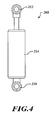
- FIGURE 4 is a side elevational view of one of the adjustable mounts of FIGURE 3 .
- FIGURE 1 shows an inertial sensor unit 100 having an inertial sensor assembly (ISA) 102 mounted within a structural chassis or housing 104.
- the inertial sensor unit 100 may be one of many units that are employed as part of an inertial navigation system (INS).
- the ISA 102 includes a plurality of sensors 106 coupled to an ISA body or mass 108.
- the sensors 106 may take the form of gyroscopes, accelerometers, or both.
- the ISA 102 is mounted within the chassis 104 in an isolated or suspended manner with a plurality of adjustable mounts 110 in which one portion of the adjustable mount 110 is coupled to the chassis 104 and a distal portion of the adjustable mount 110 is coupled to the ISA 102.
- the chassis 104 may include a number of mounting feet 111 for attaching the inertial sensor unit 100 to a portion of a vehicle.
- FIGURE 2 shows adjustable mounts 110 configured to provide adaptive isolation for the ISA 102.
- the adjustable mounts 110 may take the form of piezoelectric sensors 110 in communication with a detector 112 configured to detect an amount of pressure, acceleration, strain or force experienced by the ISA 102.
- the detector 112 transmits a first signal 114, such as an electric signal, corresponding to the detected amount of pressure, acceleration, strain or force.
- the first signal 114 received and processed by a controller or processor 116, which may cooperate with a memory 118 to evaluate the first signal 114 and determine an appropriate amount of adjustment, transmitted in the form of a second signal 120, to be applied to the adjustable mount 110.
- the memory 118 may include one or more databases having information about the ISA 102, the adjustable mount 110, and other aspects of the system 100.
- the memory 118 may include an ISA database 122 having information related to the weight, dimensions, material, etc. of the ISA 102.
- the memory 118 may include a mount database 124 having information related to the physical location, type, current settings, size, temperature, etc. for each of the adjustable mounts 110.
- the processor 116 transmits the second signal 120 to the adjustable mounts 110 to change a desired characteristic, feature, parameter or other aspect of the adjustable mount 110.
- the second signal 120 operates to change a stiffness of the adjustable mount 110, which in turns changes a natural frequency of the adjustable mount 110 to a desired natural frequency.
- the piezoelectric sensor uses the piezoelectric effect to measure pressure, acceleration, strain or force by converting them to an electrical signal.
- the piezoelectric sensor may be configured to measure the strain or acceleration corresponding to movement of the ISA 102. Depending on the configuration of the piezoelectric sensor, it may be capable of measuring the pressure, acceleration, strain or force with respect to a transverse, a longitudinal, or a shear direction.
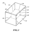
- FIGURE 3 shows an inertial sensor unit 200 having an inertial sensor assembly (ISA) 202 mounted within a structural chassis or housing 204.
- the inertial sensor unit 200 may be one of many units that are employed as part of an inertial navigation system (INS).
- the ISA 202 includes a plurality of sensors (not shown), which may be coupled to or encased within an ISA body or mass 206. The sensors may take the form of gyroscopes, accelerometers, or both.
- the ISA 202 is mounted within the chassis 204 in an isolated or suspended manner with a plurality of adjustable mounts 208.
- the adjustable mounts 208 may take the form of a magnetorheological fluid device having a first rod end 210 attachable to the ISA 202 and a second rod end 212 attached to the chassis 204.
- the magnetorheological fluid device operates when a magnetic field is applied to an encapsulated, magneto-rheological (MR) fluid within a cylinder 214, which is located between the rod ends 210, 212.
- MR magneto-rheological
- the magnetorheological fluid device may be a compact magneto-rheological fluid damper, such as the MR DamperTM; model no. RD-1005-3, manufactured by LORD® Corporation.
- the magnetorheological fluid device may take the form of the magneto-rheological fluid damper described in U.S. Patent No. 5,277,281 , which is incorporated herein in its entirety.
- the MR fluid may reversibly and instantaneously change from a freefl owing liquid to a semi-solid with a controllable yield strength when exposed to the magnetic field. More specifically, the magnetic field causes iron particles in the MR fluid to align and form a more rigid structure, thus increasing the stiffness of the magnetorheological fluid device and in turn changing a natural frequency of the device.
- the adjustable mounts 208 may advantageously respond instantly and controllably to varying levels of vibration, shock or motion.
- the acceleration of the ISA 202 may be transmitted to a processor, which in turn may determine how much to adjust the magnetic field (e.g., how much to change the stiffness of the device). It is appreciated that the MR fluid may change its characteristics quickly permitting each device in the system 200 to reach a desired stiffness almost instantaneously. By way of example, at least one known type of MR fluid can change its characteristics in less than 10 milliseconds.
- a smart material may be used for the adjustable mounts.
- the smart material may increase or decrease its stiffness based on amount of current applied to the respective mount.
- the accelerometer and/or gyroscopic data from the ISA may be used to determine the amount of current to the smart material by way of a feedback control system.
Landscapes
- Engineering & Computer Science (AREA)
- Physics & Mathematics (AREA)
- Radar, Positioning & Navigation (AREA)
- Remote Sensing (AREA)
- General Physics & Mathematics (AREA)
- General Engineering & Computer Science (AREA)
- Acoustics & Sound (AREA)
- Aviation & Aerospace Engineering (AREA)
- Mechanical Engineering (AREA)
- Automation & Control Theory (AREA)
- Fluid-Damping Devices (AREA)
- Gyroscopes (AREA)
Applications Claiming Priority (1)
| Application Number | Priority Date | Filing Date | Title |
|---|---|---|---|
| US12/271,675 US8214148B2 (en) | 2008-11-14 | 2008-11-14 | Adaptive mounting within an inertial navigation system |
Publications (2)
| Publication Number | Publication Date |
|---|---|
| EP2202488A2 true EP2202488A2 (de) | 2010-06-30 |
| EP2202488A3 EP2202488A3 (de) | 2014-04-02 |
Family
ID=42139964
Family Applications (1)
| Application Number | Title | Priority Date | Filing Date |
|---|---|---|---|
| EP09175616.3A Withdrawn EP2202488A3 (de) | 2008-11-14 | 2009-11-10 | Adaptive Montage in einem Trägheitsnavigationssystem |
Country Status (2)
| Country | Link |
|---|---|
| US (1) | US8214148B2 (de) |
| EP (1) | EP2202488A3 (de) |
Families Citing this family (15)
| Publication number | Priority date | Publication date | Assignee | Title |
|---|---|---|---|---|
| FR2967742B1 (fr) * | 2010-11-23 | 2013-11-22 | Astrium Sas | Dispositif d'isolation vibratoire |
| FR2988170B1 (fr) * | 2012-03-15 | 2014-03-14 | Thales Sa | Centrale inertielle comprenant un boitier externe et un ensemble capteur suspendu |
| GB2512019B (en) * | 2012-12-03 | 2015-08-12 | Dyson Technology Ltd | A hand dryer |
| US8954204B2 (en) | 2013-03-22 | 2015-02-10 | General Motors Llc | Collision sensor, collision sensing system, and method |
| US9096188B2 (en) * | 2013-03-22 | 2015-08-04 | General Motors Llc | Mounting sensor and aftermarket device equipped with mounting sensor |
| CN103742580A (zh) * | 2014-01-09 | 2014-04-23 | 东南大学 | 一种惯性导航组件隔振系统固有频率调整方法 |
| CN104493773B (zh) * | 2014-12-16 | 2016-05-25 | 北京航天新风机械设备有限责任公司 | 一种惯导装置安装精度调整工装 |
| FR3039641B1 (fr) * | 2015-07-31 | 2017-08-11 | Sagem Defense Securite | Dispositif de mesure inertielle a double suspension |
| CN107430003B (zh) * | 2015-12-03 | 2020-11-17 | 深圳市大疆创新科技有限公司 | 用于部件保护的系统和方法 |
| CN106704439B (zh) * | 2016-11-21 | 2018-10-16 | 大连理工大学 | 一种基于对称组合式空气弹簧的质量调谐阻尼器 |
| CN106641069B (zh) * | 2016-11-21 | 2018-10-16 | 大连理工大学 | 一种可控刚度对称组合式空气弹簧 |
| CN107218341B (zh) * | 2017-05-03 | 2019-04-30 | 武汉理工大学 | 双层主动控制减振装置和方法 |
| CN109019440B (zh) * | 2018-08-28 | 2020-10-09 | 芜湖智久机器人有限公司 | 用于叉车导航部件的自动调平装置、叉车及调平方法 |
| US11105459B2 (en) * | 2018-12-10 | 2021-08-31 | The Boeing Company | Isolation coupler for a structural assembly and method for attenuating a load |
| CN110529660B (zh) * | 2019-08-28 | 2021-01-01 | 北京工业大学 | 一种智能磁流变减振管夹 |
Citations (1)
| Publication number | Priority date | Publication date | Assignee | Title |
|---|---|---|---|---|
| US5277281A (en) | 1992-06-18 | 1994-01-11 | Lord Corporation | Magnetorheological fluid dampers |
Family Cites Families (11)
| Publication number | Priority date | Publication date | Assignee | Title |
|---|---|---|---|---|
| US3565386A (en) * | 1969-02-19 | 1971-02-23 | Gen Motors Corp | Mount for a body and coupling unit therefor |
| DE19636496C2 (de) * | 1996-09-09 | 2000-11-30 | Bosch Gmbh Robert | Federanordnung zur Lagerung eines an einem Trägerteil befestigten vibrations- oder stoßempfindlichen Gerätes in einem Gehäuse |
| US6022005A (en) * | 1996-09-27 | 2000-02-08 | Trw Inc. | Semi-active vibration isolator and fine positioning mount |
| US5890569A (en) * | 1997-06-06 | 1999-04-06 | Honeywell Inc. | Vibration isolation system for an inertial sensor assembly |
| US6578682B2 (en) * | 2001-04-26 | 2003-06-17 | Honeywell International Inc. | Compact vibration isolation system for an inertial sensor assembly |
| US6871561B2 (en) * | 2002-03-07 | 2005-03-29 | Northrop Grumman Corporation | Isolator and assembly configuration |
| US7086507B2 (en) * | 2003-05-12 | 2006-08-08 | The Board Of Regents Of The University And Community College System Of Nevada On Behalf Of The University Of Nevada, Reno | Controllable magneto-rheological elastomer vibration isolator |
| US7364022B2 (en) * | 2004-04-02 | 2008-04-29 | University Of Nevada | Controllable magneto-rheological fluid devices for motion-damping |
| US7584660B2 (en) * | 2005-07-06 | 2009-09-08 | Prueftechnik Dieter Busch Ag | Shock isolation system for an inertial sensor arrangement |
| US20070017758A1 (en) * | 2005-07-20 | 2007-01-25 | Or Siu W | Magnetorheological damper and use thereof |
| US7874407B2 (en) * | 2006-06-16 | 2011-01-25 | University Of Maryland | System and method for magnetorheological-fluid damping utilizing porous media |
-
2008
- 2008-11-14 US US12/271,675 patent/US8214148B2/en not_active Expired - Fee Related
-
2009
- 2009-11-10 EP EP09175616.3A patent/EP2202488A3/de not_active Withdrawn
Patent Citations (1)
| Publication number | Priority date | Publication date | Assignee | Title |
|---|---|---|---|---|
| US5277281A (en) | 1992-06-18 | 1994-01-11 | Lord Corporation | Magnetorheological fluid dampers |
Also Published As
| Publication number | Publication date |
|---|---|
| US20100125404A1 (en) | 2010-05-20 |
| US8214148B2 (en) | 2012-07-03 |
| EP2202488A3 (de) | 2014-04-02 |
Similar Documents
| Publication | Publication Date | Title |
|---|---|---|
| US8214148B2 (en) | Adaptive mounting within an inertial navigation system | |
| US6082719A (en) | Spacecraft antenna vibration control damper | |
| US4083433A (en) | Active vibration damper with electrodynamic sensor and drive units | |
| US9528568B2 (en) | Vibration isolation | |
| KR101210521B1 (ko) | 적응성 서스펜션 지지 시스템을 위한 장치 및 방법 | |
| EP0290181B1 (de) | Fahrzeugmotoraufhängungssysteme | |
| US7720582B2 (en) | Active suspension method and apparatus for a rotary wing aircraft | |
| US7398143B2 (en) | Active vibration absorber and method | |
| US5655757A (en) | Actively controlled damper | |
| EP0382479A1 (de) | Verfahren zum Betrieb eines Vibrationsdämpfungssystems mittels eines halbaktiven Dämpfers | |
| US20040112659A1 (en) | Active vehicle suspension with a hydraulic spring | |
| US20040150144A1 (en) | Elastomeric vibration and shock isolation for inertial sensor assemblies | |
| Tjepkema et al. | Sensor fusion for active vibration isolation in precision equipment | |
| JPS5833123B2 (ja) | カンカクオ モウケタ ブザイカンデ エネルギ−ノ デンタツオ セイギヨスルシステム | |
| EP1733903B1 (de) | Aufhängung mit variabler Dämpfung | |
| WO2006110274A1 (en) | Tunable adjustable multi-element hybrid particle damper | |
| EP3267069B1 (de) | Steuerungssystem für eine aktive antriebsstranganordnung | |
| WO2011115488A1 (en) | Active vibration isolation system, arrangement and method | |
| RU2279990C1 (ru) | Пневмогидравлическая подвеска сиденья транспортного средства | |
| JPS62155347A (ja) | アクテイブ防振支持装置 | |
| JP2585551B2 (ja) | アクティブ防振支持装置の制御方法 | |
| RU48604U1 (ru) | Динамический гаситель колебаний | |
| JPH0561484B2 (de) | ||
| KR19990020709A (ko) | 자동차의 노면가진력 조절시스템 |
Legal Events
| Date | Code | Title | Description |
|---|---|---|---|
| PUAI | Public reference made under article 153(3) epc to a published international application that has entered the european phase |
Free format text: ORIGINAL CODE: 0009012 |
|
| 17P | Request for examination filed |
Effective date: 20091110 |
|
| AK | Designated contracting states |
Kind code of ref document: A2 Designated state(s): AT BE BG CH CY CZ DE DK EE ES FI FR GB GR HR HU IE IS IT LI LT LU LV MC MK MT NL NO PL PT RO SE SI SK SM TR |
|
| AX | Request for extension of the european patent |
Extension state: AL BA RS |
|
| PUAL | Search report despatched |
Free format text: ORIGINAL CODE: 0009013 |
|
| AK | Designated contracting states |
Kind code of ref document: A3 Designated state(s): AT BE BG CH CY CZ DE DK EE ES FI FR GB GR HR HU IE IS IT LI LT LU LV MC MK MT NL NO PL PT RO SE SI SK SM TR |
|
| AX | Request for extension of the european patent |
Extension state: AL BA RS |
|
| RIC1 | Information provided on ipc code assigned before grant |
Ipc: G01C 19/5783 20120101ALI20140225BHEP Ipc: G01P 1/02 20060101ALI20140225BHEP Ipc: F16F 9/53 20060101ALI20140225BHEP Ipc: G01C 21/18 20060101AFI20140225BHEP |
|
| 17Q | First examination report despatched |
Effective date: 20141017 |
|
| RAP1 | Party data changed (applicant data changed or rights of an application transferred) |
Owner name: HONEYWELL INTERNATIONAL INC. |
|
| STAA | Information on the status of an ep patent application or granted ep patent |
Free format text: STATUS: THE APPLICATION IS DEEMED TO BE WITHDRAWN |
|
| 18D | Application deemed to be withdrawn |
Effective date: 20180602 |