EP2202501A1 - piezoelektrische Hohlanordnung für die Unterscheidung von Kräften und Momenten - Google Patents
piezoelektrische Hohlanordnung für die Unterscheidung von Kräften und Momenten Download PDFInfo
- Publication number
- EP2202501A1 EP2202501A1 EP08022373A EP08022373A EP2202501A1 EP 2202501 A1 EP2202501 A1 EP 2202501A1 EP 08022373 A EP08022373 A EP 08022373A EP 08022373 A EP08022373 A EP 08022373A EP 2202501 A1 EP2202501 A1 EP 2202501A1
- Authority
- EP
- European Patent Office
- Prior art keywords
- electrodes
- electrode
- piezoelectric
- subset
- main body
- Prior art date
- Legal status (The legal status is an assumption and is not a legal conclusion. Google has not performed a legal analysis and makes no representation as to the accuracy of the status listed.)
- Withdrawn
Links
Images
Classifications
-
- G—PHYSICS
- G01—MEASURING; TESTING
- G01L—MEASURING FORCE, STRESS, TORQUE, WORK, MECHANICAL POWER, MECHANICAL EFFICIENCY, OR FLUID PRESSURE
- G01L5/00—Apparatus for, or methods of, measuring force, work, mechanical power, or torque, specially adapted for specific purposes
- G01L5/16—Apparatus for, or methods of, measuring force, work, mechanical power, or torque, specially adapted for specific purposes for measuring several components of force
- G01L5/167—Apparatus for, or methods of, measuring force, work, mechanical power, or torque, specially adapted for specific purposes for measuring several components of force using piezoelectric means
Definitions
- the present invention relates to a sensor device that is adapted to distinguish forces and torques.
- the invention further relates to methods of use of such a device.
- Piezoelectric actuators of tubular shape are commonly used in scanning probe microscopy (SPM), in particular, scanning tunneling microscopy (STM).
- SPM scanning probe microscopy
- STM scanning tunneling microscopy
- An actuator of this kind is shown, e.g., in Figs. 7A to 7C of US 5,376,790 to Linker et al.
- the actuator comprises a hollow cylinder made from a piezoelectric material.
- Four segmented outer electrodes are distributed over the circumference of the outer wall, each electrode extending in the longitudinal direction of the cylinder and covering one quadrant, while one continuous inner electrode covers the interior of the tube.
- Such an actuator may be used for positioning an object such as a SPM tip in three spatial dimensions, i.e., for obtaining displacements along all three translational degrees of freedom (DOF).
- DOF translational degrees of freedom
- US 5,574,278 to Poirier discloses a tubular piezoelectric element having an actuator portion, the actuator portion comprising four segmented outer electrodes, and a detector portion, the detector portion comprising a single, ring-shaped outer electrode.
- This device serves to generate displacements for the two transverse translational degrees of freedom and to detect forces associated with the third, axial translational degree of freedom. No detection of torques is described.
- US 2004/0217671 discloses a tubular piezoelectric transducer that is rolled from an electroactive polymer. The document is silent about torque detection.
- the compact form of a piezoelectric bimorph is not always optimal, e.g., if it is desired to combine the device with an element, e.g. a tool, that extends along the same direction as the long axis of the device. In such situation, it may be difficult to pass the element past the device without interfering with operation of the device.
- the present invention provides a hollow piezoelectric sensor device that is capable of distinguishing forces and torques. Such a device may be utilized in a variety of different applications, in particular, in applications that require an element to be disposed in parallel to the device.
- the invention provides a sensor device as defined in claim 1.
- the device comprises:
- Electrodes Many different distributions of the electrodes are possible in order to be able to distinguish charge distributions associated with a force and a torque, and no simple general definition can be given. However, some considerations may be worth to be noted. Forces and torques are generally associated with different stress/strain profiles in the piezoelectric material, thus giving rise to different distributions of surface charges on the surfaces of the piezoelectric material.
- the electrodes should be arranged in a manner to pick up and distinguish these different surface charges. It will be readily apparent to a skilled person that there is an infinite number of electrode arrangements that will be adapted to pick up these surface charges in an appropriate manner.
- the piezoelectric device will have a generally elongated shape, with a first end, a second end, and a longitudinal axis extending from the first end to the second end.
- the hollow space will extend in the longitudinal direction. It may be open at least at the first or second end (e.g., take the form of a blind hole). Preferably it is open at both ends (e.g., taking the form of a through hole, in particular, of a cylindrical bore with arbitrary, in particular circular, polygonal or rectangular cross sectional shape).
- Distinction of charge distributions corresponding to loads associated with a force and a torque is possible, in particular, if there are at least two electrodes on the same (inner or outer) surface covering a sector along the circumferential direction around the longitudinal direction and being distributed along the axial direction along the longitudinal axis (i.e., being placed at different positions along the axial direction), in addition to least one (reference) electrode on the other surface.
- the set of electrodes may comprise a first and a second subset of electrodes, the electrodes of both subsets being present on the same surface, i.e., either on the inner surface or on the outer surface.
- the set of electrodes may comprise at least one electrode on the other surface facing the electrodes from both subsets across the piezoelectric material.
- Each subset then preferably comprises at least two electrodes at different positions along a circumferential direction around the device axis, and each electrode of the second subset is shifted along the longitudinal axis with respect to each electrode of the first subset.
- the concept of the electrodes being "shifted" may include a situation wherein each two electrodes from the first and second subset may partially overlap in a projection on the longitudinal axis, or wherein no overlap exists at all.
- each of the first and second subsets of electrodes comprises the same number of electrodes.
- each subset comprises at least three, more preferably at least four electrodes; in particular, each subset may consist of exactly four electrodes.
- all electrodes of the first and second subset have the same surface area to further simplify separation of the contributions to electrode voltages corresponding to different degrees of freedom.
- each electrode of the first subset is disposed in a axially neighboring arrangement to an electrode of the second subset. Separation of the contributions from/to loads associated with different degrees of freedom is further simplified if each electrode in each subset of electrodes is disposed in an opposing arrangement to a further electrode in the same subset, the electrodes facing each other along a transverse direction perpendicular to the longitudinal axis.
- the main body has a hollow cylindrical shape, in particular, the shape of a hollow circular cylinder.
- the main body may consist completely of the piezoelectric material.
- the hollow cylindrical shape defines a longitudinal direction and an inner and an outer circumferential surface.
- the inner circumferential surface then forms the inner surface of the main body, and the outer circumferential surface forms the outer surface of the main body.
- the cylinder may have arbitrary (circular, oval/elliptic or even polygonal) cross section.
- the cross section of the hollow space my be different from the shape of the outer circumference.
- each subset is distributed uniformly along the circumferential direction, i.e., the electrodes of each subset are placed at equal distances over the circumference of the cylinder.
- each electrode of each subset is disposed on one quadrant of the inner or (preferably) outer circumferential surface of the cylinder.
- the set of electrodes comprises an inner electrode on the inner circumferential surface and two subsets of at least three, preferably of four outer electrodes of substantially equal size and shape, each electrode being disposed on a predetermined segment of the cylinder surface, the electrodes of each subset being located in a substantially identical axial position and being distributed equally over the outer circumferential surface, each electrode of the first subset being adjacent (side-by-side) to a corresponding electrode of the second subset along the longitudinal direction.
- each of the outer electrodes will then preferably have a rectangular shape.
- the main body comprises a first piezoelectric layer having an inner surface and an outer surface, a second piezoelectric layer having an inner surface and an outer surface, and a hollow spacer disposed between the inner surface of the first piezoelectric layer and the inner surface of the second piezoelectric layer.
- the set of electrodes comprises at least one outer electrode on the outer surface of each of the first and second piezoelectric layers, and at least one inner electrode on the inner surface of the first piezoelectric layer and the inner surface of the second piezoelectric layer.
- the inner surfaces of the two piezoelectric layers may be in contact with the same inner electrode(s), or they may be in contact with different inner electrodes.
- the hollow spacer may itself be made from an electrically conducting material, forming the inner electrode of the piezoelectric device, only one single common inner electrode then being provided.
- the set of electrodes comprises four outer electrodes disposed on the outer surface of the first piezoelectric layer and four outer electrodes disposed on the outer surface of the second piezoelectric layer, the outer electrodes on the outer surfaces of each piezoelectric layer having identical shape and size (preferably rectangular), the electrodes on each of the first and second layers being arranged in identical rectangular arrangements, and each outer electrode on the first piezoelectric layer facing a corresponding outer electrode on the second piezoelectric layer across the spacer.
- the device may comprise a polymer coating and/or a polymer casing in which these components are embedded.
- Force induction elements may be provided to facilitate the transmission of forces from and to the piezoelectric device.
- the main body has a first end, a second end, and a longitudinal axis extending from the first end to the second end, the hollow portion extends along the longitudinal axis, and the device comprises at least a first force induction element disposed near the first end of said main body.
- a second force induction element disposed near the second end of the main body is provided.
- the force induction elements may be disk or tube shaped, the disk axis coinciding with the long axis of the piezoelectric layers. In the case of disks, the disks may have arbitrary shapes (circular, polygonal etc.).
- the force-induction elements will preferably have openings permitting access to the hollow space of the piezoelectric device.
- Each signal conditioning circuit will have an input being connected to at least one of said electrodes and having an output being connected to a data acquisition device for digitizing said input values, each signal conditioning circuit acting as an impedance converter having an input impedance that is higher than its output impedance.
- the present invention also encompasses methods of use of a piezoelectric device as defined above for determining both forces and torques.
- the invention encompasses a method for determining and distinguishing at least a force along a first direction and a torque around a second direction perpendicular to the first direction, the method comprising:
- a method of self-testing of a piezoelectric device as defined above comprises:
- the response voltage may be measured simultaneously with application of the excitation voltage.
- at least one of the electrodes at which the response voltage is measured is different from the electrodes to which an excitation voltage is applied.
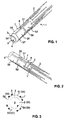
- the device 1 comprises a tube 3 of circular-cylindrical shape, made from a piezoelectric material such as PZT (lead zirconium titanate) or a polymer material such as PVDF (polyvinylidene fluoride).
- An inner electrode 5 (reference electrode) is applied to the inner surface of the piezoelectric tube 3 and fully covers this inner surface.
- a central hollow space or bore 4 extends through the device, the bore being bounded by the inner electrode 5.
- the inner electrode 5 will in the following also be designated as S0.
- Eight outer electrodes 7 are distributed over the outer circumferential surface of the tube 3.
- Electrodes S1 to S8 These electrodes will in the following be designated as electrodes S1 to S8. All electrodes are electrically conductive and are in electrical contact with the piezoelectric material.
- the electrodes may be made, e.g., of a metal or of a conductive polymer and may be attached to the piezoelectric tube by any suitable method, such as vacuum deposition techniques or bonding.
- a connecting wire 2 is connected to each electrode at a connection 8, e.g., by soldering, in order to measure voltage differences between the electrodes and/or to provide exciting voltages to the electrodes.
- the longitudinal (cylinder) axis of the device is designated as the z axis.
- the mutually orthogonal transverse directions perpendicular to the longitudinal axis are designated as the x and y directions, respectively. It is to be noted that the designation of directions is different from that of PCT/EP08/05399 for the sake of consistency with traditional usage of directions in situations where there is an exact or approximate axis of symmetry, such as here. The designation of directions given here will be adhered to throughout this document.
- the device shows in Figure 1 to 3 is particularly suited for distinguishing and determining forces applied to it along the longitudinal (z) axis or along any of the two transverse (x, y) axes, and for distinguishing and determining torques (moments) applied to it around the transverse (x, y) axes.
- the device is adapted to be used as a sensor for distinguishing and determining loads in the form of forces and torques associated with five different degrees of freedom.
- degrees of freedom is to be understood as it is normally used in the field of mechanics.
- the degrees of freedom of a rigid body are defined as the set of independent translations and rotations that specify completely any displaced position and orientation of the body.
- a rigid body generally has six degrees of freedom: three translational degrees of freedom and three rotational degrees of freedom.
- a change in the state of a body with respect to a translational degree of freedom is associated with force in a certain direction, while a change in the state of the body with respect to a rotational degree of freedom is associated with a torque (moment) around a certain direction.
- the eight outer electrodes applied to the outer circumferential surface of the tube 3 may be divided into two subgroups of four electrodes each, shifted with respect to each other along the axial (z) direction.
- the first subgroup consists of electrodes S1 to S4, while the second subgroup consists of electrodes S5 to S8. All electrodes have the same rectangular shape, covering almost a quarter of the circumference of the tube (a quadrant).
- the electrodes within each subgroup are distributed uniformly over the circumference of the tube, i.e.
- the centers of the four electrodes of each subgroup are located at positions 0°, 90°, 180° and 270° along the circumference of the tube, and their central normal vectors point into the corresponding spatial directions (the x, y, -x and -y directions).
- the second subgroup is identical to the first subgroup, however, shifted with respect to the first subgroup along the axial direction by somewhat more than the length of one single electrode.
- the electrode arrangement may be viewed as an arrangement of four segmented, elongated rectangular electrodes distributed uniformly over the circumference of the tube, wherein each segmented electrode has been divided axially into two separate sub-electrodes.
- the working principle of the device is piezoelectric. Any load applied on the piezoelectric tube 3 creates strains in the piezoelectric material, which is converted by the direct piezoelectric effect into electric displacement. Changes in electric displacements lead to surface charges, which are collected on the electrodes and may be measured as voltages by external instruments.
- a moment around the x or y axis will create a generally similar strain profile as a force along the y or -x axis, respectively, however, strain will be uniform along the z direction, and the corresponding charge distribution will therefore also be uniform.
- a moment around the z axis will create a charge profile that cannot be picked up well with the device of Figs. 1 to 3 , without providing additional electrodes, and will therefore not be considered further here.
- the different charge distributions and the different corresponding voltage distributions on the outer electrodes can be separated easily by a simple logical circuit or by well-known numerical techniques. For a generic load applied to the device, the contributions of the different degrees of freedom can thereby be easily separated.
- Table 1 Comparison of the charges created by the different loads applied on the sensor.
- Q1, Q2 and Q3 designate charges of arbitrary magnitude.
- the electrodes form the sensor output of the device, and this sensor output will be connected to a signal processing device comprising, e.g., an amplifier (depending of the force range needed to be measured) and/or an impedance converter, and a readily commercially available Data Acquisition Card, here, an eight-channel card.
- a signal processing device comprising, e.g., an amplifier (depending of the force range needed to be measured) and/or an impedance converter, and a readily commercially available Data Acquisition Card, here, an eight-channel card.
- a suitable electric circuit will be described further below.
- a general-purpose computer may then serve to calculate forces and torques from the sensor output.
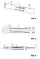
- the piezoelectric device 1 is shown together with two tube-shaped force induction elements 11 and 12. These elements are fixed to the end portions of the tube in a region of the tube where there are no outer electrodes. Any force applied to the force induction elements 11 and 12 is transferred to the tube and can be detected by the piezoelectric device 1.
- the piezoelectric device 1 may also be fully embedded in a single tubular force induction element 13, extending axially away from both ends of the device, as illustrated in Fig. 5 .
- a rod-shaped tool 14 is passed through the central bore of the device 1, along the longitudinal axis 10, without contacting the inner electrode of the device.
- any other suitable structure such as cables, tubes etc. may be passed through the central bore.
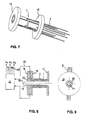
- Fig. 7 the device is shown with force induction elements 15 and 16 that have the shape of a circular disk.
- the connecting wires 2 are passed away from the device in the axial direction.
- Figure 8 illustrates a slightly different, but related embodiment.
- the connecting wires 2 are passed to the radial circumferential surface of one of the force induction elements.
- a second disk 19 is connected to the device at an axial distance to a first disk 18 mounted on one end of the tube, and the wires 2 are fed through between the two disks.
- the remaining interstitial space between the disks is filled with an electrically insulating adhesive mass 20.
- a single disk-shaped force induction element 17 similar to those of Fig. 7 is provided.
- the adhesive mass 20 also covers and protects the radial outer surface of the piezoelectric device 1.
- Figure 8 also illustrates how the wires may be connected to an signal processing device 21.
- the signal processing device 21 receives eight input values 22 in the form of voltage differences between the eight outer electrodes S1-S8 and the inner reference electrode S0, and derives five output values from these input values, the output values corresponding to forces Fx, Fy and Fz and torques Mx and My, by numerically inverting the charge-load relationship of Table 1.
- the signal processing device comprises an analog-to-digital converter (ADC) and a processor, the ADC receiving the input voltages and converting the voltages into digital voltage values, and the processor determining, from the digital voltage values, the output values 23 representing said forces and torques.
- ADC analog-to-digital converter
- output values may be displayed on a monitor screen, written to a memory for logging, or may be further processed in any conceivable way.
- Numerical methods for "inverting" the matrix of Table 1 to obtain the output values from the input values are well known in the art.
- the signal processing device may comprise a voltage source or an oscillator for exciting a vibration of the piezoelectric device 1 in a self-testing mode.
- the voltage source or oscillator provides excitation voltages to at least two or to all of the outer electrodes for exciting a vibration of the tube.
- the resulting vibrational mode is detected by measuring voltages at the electrodes and comparing these to the expected voltages. Any differences exceeding a predetermined threshold will then indicate a failure of the device.
- Other modes of operation of the self-test facility are of course possible, such as simultaneous excitation at some of the electrodes and detection at other electrodes.
- the signal processing device may also be constructed in a different way, e.g. in purely analog circuitry or by employing a general-purpose computer equipped with a data acquisition card, and that the use of such a unit is not limited to the specific piezoelectric device shown in Fig. 8 .
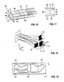
- the device comprises a main body 30 comprising two rectangular, platelike piezoelectric layers 31 and 32, which are arranged in a parallel configuration and are separated along the y direction by a central spacer element 33.
- the spacer element is manufactured from an electrically conducting material, in particular from a metal, and thereby forms the central inner electrode S0.
- the spacer element has a central bore 4, passing through the piezoelectric device along the z direction.
- the electrodes on each of the piezoelectric layers are disposed in identical rectangular arrangements.
- the electrodes can again be separated into two subsets of four electrodes each.
- the first subset consists of those four electrodes on the upper and lower piezoelectric layer 31, 32 that are closer to the first end of the device. These four electrodes are again designated as S1 to S4.
- the second subset consists of those four electrodes on the upper and lower layer that are closer to the second end of the device. These electrodes are designated as S5 to S8.
- the working principle of the device is very similar to the device of figure 1 , and forces and torques associated with five degrees of freedom may again be separated in the same manner as given in Table 1 above.
- force induction elements similar to those of the first embodiment in particular, disk- or tube-shaped force induction elements similar to those shown in Figs. 5-9 , may be used together with the device according to the second embodiment.
- Figure 13 illustrates in a very schematic fashion an alternative electrode arrangement for the device of the second embodiment.
- three outer electrodes S1', S2' and S3' are disposed, shown in solid lines, while on the outside of the lower layer, one single electrode S4' is disposed, shown in broken lines.
- the reference electrode between the two piezoelectric layers, formed again by the spacer, is not shown in this schematic illustration.
- Such a device will allow for separation of four degrees of freedom: forces in the x, y and z direction and torque around the x axis. It is readily apparent from this exemplary illustration that an infinite number of other electrode arrangements will be possible to achieve separation of at least four degrees of freedom, not only for the second embodiment, but also for the first, tubular embodiment.
- the devices described above not only be used for detecting loads, but may also be used to generate loads (forces and torques) associated with at least four different degrees of freedom, instead of measuring such loads, simply by applying corresponding voltages to the electrodes.
- loads force and torques
- voltages as given in Table 1 may be applied to generate forces Fx, Fy, and Fz and torques Mx and My.
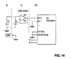
- FIG. 14 illustrates an advantageous setup for signal conditioning of the sensor output.
- Each electrode of the sensor may be connected to a circuit like the one shown in Fig. 14 .
- the sensor S is modeled as a sensor capacitance C s . This capacitance is connected in parallel to an external capacitor, C x .
- the sensor output is fed to a signal conditioning circuit C acting as an impedance converter, based on an LMC6464 op-amp which was chosen because of its low bias current and offset current.
- This conditioning circuit (supply voltages +V/-V) has a high internal resistance (approx. 10 TOhm) which enables readout of DC signals.
- the DAQ card National Instruments NI-6014 was chosen because of its high input resistance, 100 GOhm. Between each signal from the sensor a ground-connected input to the DAQ card may be provided to reduce cross talk.
- the user USR of the sensor the AI Sns common input and the AI/AO GND may also be connected to the same ground.
Landscapes
- Physics & Mathematics (AREA)
- General Physics & Mathematics (AREA)
- Force Measurement Appropriate To Specific Purposes (AREA)
Priority Applications (1)
| Application Number | Priority Date | Filing Date | Title |
|---|---|---|---|
| EP08022373A EP2202501A1 (de) | 2008-12-23 | 2008-12-23 | piezoelektrische Hohlanordnung für die Unterscheidung von Kräften und Momenten |
Applications Claiming Priority (1)
| Application Number | Priority Date | Filing Date | Title |
|---|---|---|---|
| EP08022373A EP2202501A1 (de) | 2008-12-23 | 2008-12-23 | piezoelektrische Hohlanordnung für die Unterscheidung von Kräften und Momenten |
Publications (1)
| Publication Number | Publication Date |
|---|---|
| EP2202501A1 true EP2202501A1 (de) | 2010-06-30 |
Family
ID=40626648
Family Applications (1)
| Application Number | Title | Priority Date | Filing Date |
|---|---|---|---|
| EP08022373A Withdrawn EP2202501A1 (de) | 2008-12-23 | 2008-12-23 | piezoelektrische Hohlanordnung für die Unterscheidung von Kräften und Momenten |
Country Status (1)
| Country | Link |
|---|---|
| EP (1) | EP2202501A1 (de) |
Cited By (4)
| Publication number | Priority date | Publication date | Assignee | Title |
|---|---|---|---|---|
| JP2012122790A (ja) * | 2010-12-07 | 2012-06-28 | Seiko Epson Corp | センサー装置及びセンサー装置アレイ |
| WO2015193176A1 (en) * | 2014-06-20 | 2015-12-23 | Alemnis Gmbh | Material testing device |
| US20180248232A1 (en) * | 2016-06-09 | 2018-08-30 | Lg Chem, Ltd. | Apparatus for measuring variation in thickness of electrode of secondary battery and secondary battery with the same mounted therein |
| CN113508283A (zh) * | 2019-01-28 | 2021-10-15 | 基斯特勒控股公司 | 采集轨道负载的装置和将该装置安装在轨道中的方法 |
Citations (10)
| Publication number | Priority date | Publication date | Assignee | Title |
|---|---|---|---|---|
| US4513437A (en) | 1982-06-30 | 1985-04-23 | International Business Machines Corporation | Data input pen for Signature Verification |
| US5376790A (en) | 1992-03-13 | 1994-12-27 | Park Scientific Instruments | Scanning probe microscope |
| US5402684A (en) * | 1992-10-23 | 1995-04-04 | K.K. Holding Ag | Multicomponent force and moment measuring arrangement |
| US5524354A (en) | 1992-12-21 | 1996-06-11 | Carl Zeiss Jena Gmbh | Probe element for coordinate measurement systems |
| US5574278A (en) | 1995-05-23 | 1996-11-12 | The United States Of America As Represented By The Secretary Of Commerce | Atomic force microscope using piezoelectric detection |
| US5912461A (en) | 1995-09-22 | 1999-06-15 | Olympus Optical Co., Ltd. | Probe scanning mechanism for a scanning probe microscope |
| US6194813B1 (en) | 1999-09-29 | 2001-02-27 | Jacob Israelachvili | Extended-range xyz linear piezo-mechanical scanner for scanning-probe and surface force applications |
| JP2004159403A (ja) * | 2002-11-05 | 2004-06-03 | Seiko Epson Corp | 圧電アクチュエータ |
| US20040217671A1 (en) | 2001-05-22 | 2004-11-04 | Sri International, A California Corporation | Rolled electroactive polymers |
| WO2009007047A2 (en) | 2007-07-06 | 2009-01-15 | Eth Zurich | Piezoelectric device for detecting or generating forces and torques in multiple directions |
-
2008
- 2008-12-23 EP EP08022373A patent/EP2202501A1/de not_active Withdrawn
Patent Citations (10)
| Publication number | Priority date | Publication date | Assignee | Title |
|---|---|---|---|---|
| US4513437A (en) | 1982-06-30 | 1985-04-23 | International Business Machines Corporation | Data input pen for Signature Verification |
| US5376790A (en) | 1992-03-13 | 1994-12-27 | Park Scientific Instruments | Scanning probe microscope |
| US5402684A (en) * | 1992-10-23 | 1995-04-04 | K.K. Holding Ag | Multicomponent force and moment measuring arrangement |
| US5524354A (en) | 1992-12-21 | 1996-06-11 | Carl Zeiss Jena Gmbh | Probe element for coordinate measurement systems |
| US5574278A (en) | 1995-05-23 | 1996-11-12 | The United States Of America As Represented By The Secretary Of Commerce | Atomic force microscope using piezoelectric detection |
| US5912461A (en) | 1995-09-22 | 1999-06-15 | Olympus Optical Co., Ltd. | Probe scanning mechanism for a scanning probe microscope |
| US6194813B1 (en) | 1999-09-29 | 2001-02-27 | Jacob Israelachvili | Extended-range xyz linear piezo-mechanical scanner for scanning-probe and surface force applications |
| US20040217671A1 (en) | 2001-05-22 | 2004-11-04 | Sri International, A California Corporation | Rolled electroactive polymers |
| JP2004159403A (ja) * | 2002-11-05 | 2004-06-03 | Seiko Epson Corp | 圧電アクチュエータ |
| WO2009007047A2 (en) | 2007-07-06 | 2009-01-15 | Eth Zurich | Piezoelectric device for detecting or generating forces and torques in multiple directions |
Non-Patent Citations (1)
| Title |
|---|
| R. PÉREZ ET AL.: "Modeling, Fabrication, and Validation of a High-Performance 2-DoF Piezoactuator for Micromanipulation", IEEFJASME TRANSACTIONS ON MECHATRONICS, vol. 10, no. 2, pages 161 - 171, XP011130009, DOI: doi:10.1109/TMECH.2005.844712 |
Cited By (5)
| Publication number | Priority date | Publication date | Assignee | Title |
|---|---|---|---|---|
| JP2012122790A (ja) * | 2010-12-07 | 2012-06-28 | Seiko Epson Corp | センサー装置及びセンサー装置アレイ |
| WO2015193176A1 (en) * | 2014-06-20 | 2015-12-23 | Alemnis Gmbh | Material testing device |
| US20180248232A1 (en) * | 2016-06-09 | 2018-08-30 | Lg Chem, Ltd. | Apparatus for measuring variation in thickness of electrode of secondary battery and secondary battery with the same mounted therein |
| US10777853B2 (en) * | 2016-06-09 | 2020-09-15 | Lg Chem, Ltd. | Apparatus for measuring variation in thickness of electrode of secondary battery and secondary battery with the same mounted therein |
| CN113508283A (zh) * | 2019-01-28 | 2021-10-15 | 基斯特勒控股公司 | 采集轨道负载的装置和将该装置安装在轨道中的方法 |
Similar Documents
| Publication | Publication Date | Title |
|---|---|---|
| Wei et al. | An overview of micro-force sensing techniques | |
| JPH0666663A (ja) | 微小センサおよびその製法 | |
| CN112649128B (zh) | 一种测量三维接触应力的传感装置及方法 | |
| US20160076953A1 (en) | Flexible sensors and related systems for determining forces applied to an object, such as a surgical instrument, and methods for manufacturing same | |
| KR20170066391A (ko) | 개선된 전자-기계적 센서 | |
| US6581481B1 (en) | Capacitive extensometer | |
| CN103562696A (zh) | 具有压电转换器的传感器元件 | |
| CN109313007B (zh) | 间隙传感器以及间隙测量方法 | |
| US7069795B2 (en) | Sensor using electro active curved helix and double helix | |
| CN105066863A (zh) | 基于电活性高弹体聚合物的位移传感器 | |
| JP2022191485A (ja) | 多軸触覚センサ | |
| Kim et al. | Design and realization of grasper-integrated force sensor for minimally invasive robotic surgery | |
| US10060805B2 (en) | MEMS piton-tube capacitive force sensor | |
| CN113302414B (zh) | 用于轴承的传感支承装置 | |
| Zhang et al. | Design and fabrication of a thin and soft tactile force sensor array based on conductive rubber | |
| US20050231066A1 (en) | Fine-adjustment mechanism for scanning probe microscopy | |
| WO2009007047A2 (en) | Piezoelectric device for detecting or generating forces and torques in multiple directions | |
| US7174792B2 (en) | Multi-axis transducer | |
| JPS6122887B2 (de) | ||
| JPH06201502A (ja) | 圧力センサ | |
| JPH0843430A (ja) | 圧電型振動センサとその製法 | |
| JP2010112864A (ja) | 力センサー | |
| JP2008544262A (ja) | 圧力センサ | |
| KR20250172938A (ko) | 단방향성, 양방향성 또는 전방향성 변형 측정을 위한 가요성 압전 소자 | |
| CN118329265A (zh) | 一种基于感觉毛结构的三维力柔性触觉传感器及其阵列 |
Legal Events
| Date | Code | Title | Description |
|---|---|---|---|
| PUAI | Public reference made under article 153(3) epc to a published international application that has entered the european phase |
Free format text: ORIGINAL CODE: 0009012 |
|
| AK | Designated contracting states |
Kind code of ref document: A1 Designated state(s): AT BE BG CH CY CZ DE DK EE ES FI FR GB GR HR HU IE IS IT LI LT LU LV MC MT NL NO PL PT RO SE SI SK TR |
|
| AX | Request for extension of the european patent |
Extension state: AL BA MK RS |
|
| AKY | No designation fees paid | ||
| REG | Reference to a national code |
Ref country code: DE Ref legal event code: R108 Effective date: 20110208 Ref country code: DE Ref legal event code: 8566 |
|
| STAA | Information on the status of an ep patent application or granted ep patent |
Free format text: STATUS: THE APPLICATION IS DEEMED TO BE WITHDRAWN |
|
| 18D | Application deemed to be withdrawn |
Effective date: 20110104 |