EP2202502A2 - Appareil et procédé de mesure de la dispersion chromatique - Google Patents
Appareil et procédé de mesure de la dispersion chromatique Download PDFInfo
- Publication number
- EP2202502A2 EP2202502A2 EP09252876A EP09252876A EP2202502A2 EP 2202502 A2 EP2202502 A2 EP 2202502A2 EP 09252876 A EP09252876 A EP 09252876A EP 09252876 A EP09252876 A EP 09252876A EP 2202502 A2 EP2202502 A2 EP 2202502A2
- Authority
- EP
- European Patent Office
- Prior art keywords
- wavelength
- light
- pump
- probe
- idler
- Prior art date
- Legal status (The legal status is an assumption and is not a legal conclusion. Google has not performed a legal analysis and makes no representation as to the accuracy of the status listed.)
- Granted
Links
- 239000006185 dispersion Substances 0.000 title claims abstract description 97
- 238000000034 method Methods 0.000 title claims description 30
- 239000000523 sample Substances 0.000 claims abstract description 98
- 238000012360 testing method Methods 0.000 claims abstract description 12
- 238000004364 calculation method Methods 0.000 claims abstract description 9
- 230000001902 propagating effect Effects 0.000 claims abstract description 3
- 239000013307 optical fiber Substances 0.000 claims description 21
- 238000004458 analytical method Methods 0.000 claims description 10
- 230000000644 propagated effect Effects 0.000 claims description 2
- 230000003287 optical effect Effects 0.000 abstract description 32
- 238000005259 measurement Methods 0.000 abstract description 18
- 230000010287 polarization Effects 0.000 description 19
- 239000000835 fiber Substances 0.000 description 16
- 238000006243 chemical reaction Methods 0.000 description 13
- 230000005540 biological transmission Effects 0.000 description 6
- 238000010586 diagram Methods 0.000 description 4
- 238000004088 simulation Methods 0.000 description 3
- VYPSYNLAJGMNEJ-UHFFFAOYSA-N Silicium dioxide Chemical compound O=[Si]=O VYPSYNLAJGMNEJ-UHFFFAOYSA-N 0.000 description 2
- 238000004891 communication Methods 0.000 description 2
- 230000008878 coupling Effects 0.000 description 2
- 238000010168 coupling process Methods 0.000 description 2
- 238000005859 coupling reaction Methods 0.000 description 2
- 239000000203 mixture Substances 0.000 description 2
- 238000000253 optical time-domain reflectometry Methods 0.000 description 2
- 230000000737 periodic effect Effects 0.000 description 2
- 238000001228 spectrum Methods 0.000 description 2
- 229910052691 Erbium Inorganic materials 0.000 description 1
- 238000001069 Raman spectroscopy Methods 0.000 description 1
- 229910052775 Thulium Inorganic materials 0.000 description 1
- 238000007796 conventional method Methods 0.000 description 1
- 238000001514 detection method Methods 0.000 description 1
- 230000004069 differentiation Effects 0.000 description 1
- 230000000694 effects Effects 0.000 description 1
- UYAHIZSMUZPPFV-UHFFFAOYSA-N erbium Chemical compound [Er] UYAHIZSMUZPPFV-UHFFFAOYSA-N 0.000 description 1
- 238000011156 evaluation Methods 0.000 description 1
- 238000002474 experimental method Methods 0.000 description 1
- 230000007246 mechanism Effects 0.000 description 1
- 238000012986 modification Methods 0.000 description 1
- 230000004048 modification Effects 0.000 description 1
- 238000012544 monitoring process Methods 0.000 description 1
- 230000010363 phase shift Effects 0.000 description 1
- 238000012545 processing Methods 0.000 description 1
- 229910052761 rare earth metal Inorganic materials 0.000 description 1
- 238000011160 research Methods 0.000 description 1
- 239000004065 semiconductor Substances 0.000 description 1
- 239000000377 silicon dioxide Substances 0.000 description 1
- FRNOGLGSGLTDKL-UHFFFAOYSA-N thulium atom Chemical compound [Tm] FRNOGLGSGLTDKL-UHFFFAOYSA-N 0.000 description 1
- 238000002366 time-of-flight method Methods 0.000 description 1
Images


Classifications
-
- G—PHYSICS
- G01—MEASURING; TESTING
- G01M—TESTING STATIC OR DYNAMIC BALANCE OF MACHINES OR STRUCTURES; TESTING OF STRUCTURES OR APPARATUS, NOT OTHERWISE PROVIDED FOR
- G01M11/00—Testing of optical apparatus; Testing structures by optical methods not otherwise provided for
- G01M11/30—Testing of optical devices, constituted by fibre optics or optical waveguides
- G01M11/33—Testing of optical devices, constituted by fibre optics or optical waveguides with a light emitter being disposed at one fibre or waveguide end-face, and a light receiver at the other end-face
- G01M11/338—Testing of optical devices, constituted by fibre optics or optical waveguides with a light emitter being disposed at one fibre or waveguide end-face, and a light receiver at the other end-face by measuring dispersion other than PMD, e.g. chromatic dispersion
Definitions
- the present invention relates to apparatus and methods for measuring chromatic dispersion.
- chromatic dispersion of an optical component causes broadening of an incident signal light pulse.
- Various methods have been examined for precisely measuring chromatic dispersions of optical components in order to evaluate them. Examples of methods for measuring chromatic dispersions of optical components include a time-of-flight method ( L. G. Cohen and C. Lin: IEEE J. Quantum Electron. QE-14 (1978) No.11, p.855 ), a modulated signal phase shift method ( B. Costa, et al.: IEEE J. Quantum Electron. QE-18 (1982) No. 10, p.1509 ), and an interference method ( Kazunori Naganuma: NTT R&D vol.42 (1993) p.1049 ). Moreover, a method of measuring the chromatic dispersion by means of four-wave mixing (FWM) is also studied ( T. Hasegawa, et al.: OFC2006, paper OTuH5, 2006 ).
- FWM four-wave mixing
- the highly nonlinear fiber is a fiber in which the efficiency of generating nonlinear phenomenon is enhanced, and in many cases, it is used as a device in which FWM is applied in a length having tens of meters to hundreds of meters.
- the object of the present invention is to provide apparatus having a simple measurement set-up, as well as measuring methods, with which chromatic dispersion of a device under test that is an optical component can be measured with high accuracy.
- the chromatic dispersion measuring apparatus comprises: a pump light source for emitting pump light with a wavelength ⁇ pump ; a probe light source for emitting probe light with a wavelength ⁇ probe ; a measuring means for measuring the power of idler light having a wavelength ⁇ idler that is output from a device under test according to four-wave mixing generated by propagation of the pump light and the probe light through the device; and an analysis tool for calculating a chromatic dispersion of the device at a specific wavelength ⁇ pump by seeking the generation efficiency of idler light relative to the wavelength ⁇ probe when the pump light having a specific wavelength is propagated and by seeking the frequency difference or wavelength difference between the pump light and the probe light that makes an extremum of generation efficiency of the idler light and calculating the phase mismatch among the pump light wavelength having such frequency difference or wavelength difference, the corresponding probe light wavelength, and the corresponding idler light wavelength in the device.
- a chromatic dispersion measuring method for calculating chromatic dispersions of a device under test.
- the method comprises: propagating pump light having a specific wavelength ⁇ pump and probe light having a wavelength ⁇ probe through a device under test; seeking the generation efficiency of idler light with respect to the wavelength ⁇ pump by measuring the power of the idler light having a wavelength ⁇ idler that is output from the device according to four-wave mixing generated in the device; seeking the frequency difference or frequency difference or wavelength difference between the pump light and the probe light that makes the generation efficiency of the idler light an extremum; calculating the phase mismatch among the pump light wavelength having such frequency difference or wavelength difference, the corresponding probe light wavelength, and the corresponding idler light wavelength; and calculating, from such calculation results, a chromatic dispersion of the device at the specific wavelength ⁇ pump .
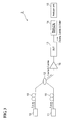
- Figure 1 is a conceptional schematic diagram of a chromatic dispersion measuring apparatus relating to an embodiment of the present invention.
- Figure 2 is a graph showing the ⁇ 2 dependence of FWM generation efficiency.
- Figure 3 is a conceptional schematic diagram of a chromatic dispersion measuring apparatus relating to another embodiment of the present invention.
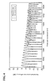
- Figure 4 is a graph plotting normalized conversion efficiencies relative to the probe light wavelength ⁇ probe .
- Figure 5 is a graph showing the ⁇ 2 dependence of the normalized conversion efficiency.
- Figures 6 shows the pump light wavelength dependence of chromatic dispersion (Disp).
- FIG. 1 is a conceptional schematic diagram of a chromatic dispersion measuring apparatus 1 relating to an embodiment of the present invention.
- the chromatic dispersion measuring apparatus 1 comprises a pump light source 10, a probe light source 11, an optical coupler 12, a device under test (DUT) 13, a measuring instrument 14, an analyzer unit 15, an optical amplifier 16, a bandpass filter 17, polarization controllers 18 and 19, and a polarization monitor 20.
- the pump light source 10 is a light source for outputting pump light with a wavelength ⁇ pump : a wavelength tunable light source capable of tunably outputting a single wavelength, or a wideband light source is suitably used therefor.
- the wavelength ⁇ pump of the pump light that is incident on the DUT 13 is set to be different from the wavelength ⁇ probe of the below-mentioned probe light. Also, it is preferable that the intensity of the pump light incident on the DUT 13 be sufficiently high to the extent that little nonlinear phenomenon other than FWM will occur, and the intensity will be set in the range of 10 mW to several W, for example.
- the probe light source 11 is a light source for outputting probe light with a wavelength ⁇ probe , and a wideband light source or a wavelength tunable light source capable of tunably outputting a single wavelength is suitably used therefor.
- the wavelength of the probe light should be designed not to include the wavelength ⁇ pump of the pump light at a time when the probe light is incident on the DUT 13. It is preferable that the intensity of the probe light incident on the DUT 13 be sufficiently high to the extent that little nonlinear phenomenon other than FWM will occur; however, it may be not so high as the intensity of the pump light. More specifically, the incident light intensity of the probe light is in the range of about 0.1 mW to several W.
- the probe light When the probe light is made incident on the DUT 13, one or both of the pump light and the probe light consist of substantially a single wavelength.
- the probe light is preferably such that the ratio of the half width at half maximum is 0.5 % or less relative to the central wavelength, for example, and the smaller this ratio, the better.
- the idler light having a wavelength ⁇ idler is generated according to the four-wave mixing, i.e., a nonlinear optical phenomenon, which occurs in the DUT 13 as a result of the propagation of the pump light and the probe light.
- An amplifier 16 has a function to emit amplified light by amplifying the pump light that has been input thereinto from the pump light source 10.
- a Raman amplifier, an optical semiconductor amplifier (OSA), and a rare-earth ion doped optical amplifier are preferably used.
- the amplifier 16 is unnecessary in the case where the light intensity of the pump light output from the pump light source 10 is sufficiently high: more specifically, it will be sufficient if there is an output of several W to tens of mW.
- the bandpass filter 17 has a function of allowing only the light having a frequency of necessary range to pass out of the pump light that has been output from the amplifier 16, and to attenuate the other light having a frequency of unnecessary range. It is preferable to provide the bandpass filter 17 when the optical noise from amplifier 16 is so significant as to make the detection of idler light difficult; however, it is not essential.
- the polarization controllers 18 and 19 are provided for the purpose of arranging the status of polarization of the pump light and the probe light so as to coincide with each other. More specifically, the polarization controller 18 outputs the pump light to the optical coupler 12 after adjusting the polarization state of incident pump light. Also, the polarization controller 19 outputs the probe light to the optical coupler 12 after adjusting the polarization state of incident probe light.
- the polarization controllers 18 and 19 are not essential; however, it is preferable to provide them because the output power of the idler light becomes stronger when the states of polarization of the pump light and the probe light are arranged to coincide with each other. It is unnecessary to provide the polarization controllers 18 and 19 in the case where either one or both of the states of polarization of the probe light and the pump light are scrambled to make the states of polarization random.
- the optical coupler 12 is provided to combine the pump light and the probe light so as to make them incident on the DUT 13 at the same time.
- the pump light and the probe light may be made incident on the DUT 13 using a spatial optical system such as lens or the like instead of using the optical coupler 12.
- the polarization monitor 20 is provided downstream of the optical coupler 12 in an arm different from the DUT 13 so as to confirm whether the states of polarization of the pump light and the probe light are coincident.
- the measuring instrument 14 is a measuring means for measuring the output power of the idler light that is output from the DUT 13 according to four-wave mixing generated by propagation of the pump light and the probe light through the DUT 13. More specifically, the measuring instrument 14 is constituted by an optical spectrum analyzer (OSA), or a combination of a monochromator for picking up only the idler light wavelength that is the measurement target, and a photodetector such as an optical calorimeter. Also, the measuring instrument 14 may have a function of calculating the incident light intensities of the pump light and the probe light that are incident on the DUT 13 by simultaneously monitoring the output light intensities of the pump light and the probe light that are output therefrom.
- OSA optical spectrum analyzer
- the measuring instrument 14 may have a function of calculating the incident light intensities of the pump light and the probe light that are incident on the DUT 13 by simultaneously monitoring the output light intensities of the pump light and the probe light that are output therefrom.
- the analyzer unit 15 is an analysis tool for calculating the chromatic dispersion of the DUT 13 according to the output intensities of idler light as measured by the measuring instrument 14. The manner of calculating the chromatic dispersion by the analysis tool will be described later.
- Equations (2), (3), and (4) chromatic dispersion (Disp), dispersion slope (Slope), wavelength dependence (dS/d ⁇ ) of the dispersion slope, which are used in the optical communication, are calculated by Equations (2), (3), and (4), respectively:
- the generation efficiency of the idler light that is, P idler P probe ⁇ P idler 2 , (wherein P idler is a power of the idler light output from the DUT 13, P probe is a power of the probe light incident to the DUT 13, and P pum ⁇ is a power of the pump light incident to the DUT 13) can be written as Equation (7):
- P idler P probe ⁇ P pump 2 ⁇ ⁇ Leff 2 ⁇ exp - ⁇ linear ⁇ L ⁇ ⁇
- ⁇ is a nonlinear coefficient of the DUT 13
- Leff is an effective length of the DUT 13
- ⁇ linear is a
- Equation (7) the parameters ⁇ , ⁇ linear , Leff, L, and P pump , which are included in Equation (7), are values determined by the characteristics of the DUT 13 and the experiment conditions and can be treated as coefficients.
- Equation (11) is differentiated with respect to X, which is defined as shown by Equation (12):
- X ⁇ ⁇ ⁇ L / 2
- the phase matching parameter ⁇ has a minimal value (in the case of X ⁇ 0).
- Equation (15): - sin X + X ⁇ cos X 0 is satisfied, ⁇ has a maximal value.
- Equation (18) ⁇ ⁇ ⁇ ⁇ 2 ⁇ N + 1 ⁇ ⁇ / L
- Equation (19) ⁇ n_p represents ⁇ n at the pump light frequency.
- ⁇ n_ z is ⁇ n at the zero-dispersion frequency ⁇ z .
- Equation (20) ⁇ ⁇ ⁇ ⁇ 2 ⁇ L / 2
- Equation (25) the difference between the reciprocal of adjacent values of ⁇ 2 for making a minimal value of FWM generation efficiency is ⁇ 2_p ⁇ L/(2 ⁇ ), which makes it possible to obtain ⁇ 2 at the pump light frequency.
- ⁇ 2_p ⁇ L/(2 ⁇ ) the difference between the reciprocal of adjacent values of ⁇ 2 for making a minimal value of FWM generation efficiency.
- Figure 2 is a graph showing the ⁇ 2 dependence of the FWM efficiency.
- Difference L1 is an example of the difference of adjacent minimal values.
- Difference L2 is an example of the difference of adjacent maximal values.
- the reciprocal of L1 and L2 becomes " ⁇ 2_p ⁇ L/(2 ⁇ )" and using this, it is possible to obtain ⁇ 2 at the pump light frequency.
- the wavelength dependence of ⁇ 2 can be measured by conducting a similar measurement while changing the pump light frequency, and furthermore it is possible to obtain high-order dispersions such as a third-order dispersion ⁇ 3 at the wavelength ⁇ pump of the device under test and a fourth-order dispersion ⁇ 4 at the wavelength ⁇ pump of the device. Since it is sufficient if the period of the relationship on ⁇ 2 is found, it is theoretically possible to measure dispersions regardless of ⁇ 2 .
- phase mismatch ⁇ is possible from the relationship of Equation (5), and also by using the relationship of Equations (1) to (4), etc, it is possible to convert an n-th order dispersion ⁇ n into a chromatic dispersion parameter d n-1 ( ⁇ 1 )/d ⁇ n-1 (n ⁇ 2), which is generally used in fiber optics.
- FIG. 3 is a conceptional schematic diagram of a chromatic dispersion measuring apparatus 2 relating to another embodiment of the present invention. Chromatic dispersions of an optical fiber as a DUT 13 were measured using the chromatic dispersion measuring apparatus 2. The compositions of equipment included in the chromatic dispersion measuring apparatus 2 are as described in the following.
- Wavelength-tunable LD light sources were used as a pump light source 10 and a probe light source 11.
- the half width at half maximum of these light sources was 0.1 nm or less.
- the wavelength ⁇ pump of the pump light was set to 1530, 1550, 1570, 1590, and 1610 nm, and in each of such cases the wavelength ⁇ probe of the probe light was tuned at 0.1 nm intervals in the range of ⁇ pump +5nm to ⁇ pump +13mn.
- polarization controllers 18 and 19 which were arranged on the respective optical paths of the pump light and the probe light, the states of polarization of the pump light and the probe light that were put into the optical fiber 13 are aligned to be coincide with each other.
- a 3-dB optical coupler was used as the optical coupler 12.
- the intensities of the pump light, the probe light and the idler light were measured using an optical spectrum analyzer (OSA).
- OSA optical spectrum analyzer
- the transmission loss of the optical fiber, and the coupling loss relating to the optical fiber and the OSA the respective incident intensities of the pump light and the probe light incident onto the optical fiber were calculated.
- the output power of the idler light was calculated on the basis of the optical coupling loss relating to the optical fiber and the OSA.
- the conversion efficiencies of the idler light were obtained using Equation (7), and the so-called efficiencies were changed into normalized values (normalized conversion efficiencies) relative to the maximum value of the efficiency.
- Figure 4 is a graph plotting normalized conversion efficiencies relative to the probe light wavelength ⁇ probe in the case where an optical fiber having the characteristics shown in Table I was used as the DUT 13 and the pump light wavelength was fixed at 1570 nm.
- Table I Item Value Transmission loss @ 1.55 ⁇ m 0.50 dB/km (0.12/km) Aeff 10 ⁇ m 2 Polarization mode dispersion 0.02 ps/ ⁇ km Cutoff wavelength 1350 nm Length 23 m Nonlinear coefficient 21 /w/km
- Figure 5 is a graph showing the ⁇ 2 dependence of the normalized conversion efficiency.
- the solid line of Fig. 4 shows calculation values of the normalized conversion efficiency that were obtained using the calculation values of ⁇ 2 . It is seen that the calculation values of the normalized conversion efficiency are well coincident with the measurement values.
- Figures 6 is a graph plotting, relative to the pump light wavelength, the chromatic dispersion (Disp) obtained at each wavelength as in the above-mentioned analysis.
- the chromatic dispersions (Disp) at 1530, 1550, 1570, 1590, and 1610 nm were -17.2 ps/nm/km, -16.8 ps/nm/km, -16.5 ps/nm/km, -16.3 ps/nm/km, and -16.0 ps/nm/km, respectively.
- the solid line is a straight line linearly approximated using the least squares method. From the inclination of the solid line, it was possible to calculate that the dispersion slope of the optical fiber was +0.015 ps/nm 2 /km.
- the chromatic dispersion measuring method of the present invention if the power of the pump light wavelength increases by twice (3dB), then the same conversion efficiency can be obtained even if the fiber length is 1/2. For example, it is possible to measure the chromatic dispersion of a fiber having a length of 10 m or less (e.g., several m).
- special equipment such as a streak camera or modulator is not needed, and it is possible to measure the dispersion value in such a wavelength band as 1- ⁇ m band or 2- ⁇ m band, for example, which is not generally used for optical communication.
- the pump light source is preferably a wavelength-tunable light source.
- the analysis tool calculates, in a plurality of wavelengths of the pump light, phase mismatches among the probe light wavelength, the idle light wavelength, and the pump light wavelength that makes an extremum of the generation efficiency, and calculates the chromatic dispersion at each wavelength of the pump light.
- the wavelength ⁇ pump be different from the zero-dispersion wavelength of the device under test.
- the pulse width when the pulse width is 0.5 ns, the correlation length of the pump light and the probe light is about 0.1 m. Similarly, when the pulse width is 5 ns, the correlation length is about 1 m. When the pulse width is 500 ns, the correlation length is about 100 m, and when the pulse width is 1000 ns, the correlation length is about 200 m. If the DUT 13 is an optical fiber, it is preferable to set the pulse width in the range of 0.5 to 1000 ns.
- the method of L. F. Mollenauer, et al.: in Opt. Lett. vo1.21 (1996) p.1724 is such that FWM light from two pulsed light waves having wavelengths that are distanced from each other are measured with the optical time domain reflectometry (OTDR) method, so that a dispersion value in the longitudinal direction is obtained from the instantaneous frequency.
- OTDR optical time domain reflectometry
- this method suffers from a significant measurement error because it relies on an instantaneous frequency while a significant dead zone exists in the incident end portion and the positional resolution is about 100 m or more.
- the chromatic dispersion measuring apparatus and method of the present invention exhibit advantageous effect that the chromatic dispersion can be measured with high precision, without using a numerical simulation, or the like, and that the realization of such high precision measurement does not require expensive equipment compositions.
- the wavelength dispersion (or ⁇ 2 ) of an optical fiber should be uniform, it is easy to obtain a uniform wavelength dispersion (for example, distribution with a variation of ⁇ 5 % or less) since the length of the optical fiber for which high precision measurement of the zero-dispersion wavelength or high-order dispersion is needed is as short as 1 km or less. That is, the chromatic dispersion measuring method of the invention can suitably be used for an optical fiber having a length of several m to about 1 km.
- the polarization mode dispersion (PMD) of the DUT 13 the better; however, when the DUT 13 is an optical fiber, it is possible to accomplish the measurement if PMD is 0.5 ps or less in the full length of the fiber.
- the conventional method has required single-mode propagation at the measurement wavelength; however, in the method of the invention, the high mode in which the zero-dispersion wavelength is not in the vicinity of the measurement range does not satisfy the relationship of Equation (19), and therefore it does not become a noise factor. Since the nonlinear phenomenon is used, the higher the nonlinear coefficient of the fiber, the easier the measurement. However, even in the case of a low nonlinear coefficient, the measurement can be accomplished by increasing the pump light intensity. For example, it is also possible to measure the chromatic dispersion of a standard single-mode fiber having a nonlinear coefficient ⁇ of 2/W/km.
Landscapes
- Chemical & Material Sciences (AREA)
- Physics & Mathematics (AREA)
- Dispersion Chemistry (AREA)
- Optics & Photonics (AREA)
- Analytical Chemistry (AREA)
- General Physics & Mathematics (AREA)
- Optical Modulation, Optical Deflection, Nonlinear Optics, Optical Demodulation, Optical Logic Elements (AREA)
- Investigating Or Analysing Materials By Optical Means (AREA)
Applications Claiming Priority (1)
| Application Number | Priority Date | Filing Date | Title |
|---|---|---|---|
| JP2008331242A JP2010151674A (ja) | 2008-12-25 | 2008-12-25 | 波長分散測定装置及び波長分散測定方法 |
Publications (3)
| Publication Number | Publication Date |
|---|---|
| EP2202502A2 true EP2202502A2 (fr) | 2010-06-30 |
| EP2202502A3 EP2202502A3 (fr) | 2016-07-20 |
| EP2202502B1 EP2202502B1 (fr) | 2017-05-03 |
Family
ID=42040473
Family Applications (1)
| Application Number | Title | Priority Date | Filing Date |
|---|---|---|---|
| EP09252876.9A Not-in-force EP2202502B1 (fr) | 2008-12-25 | 2009-12-22 | Appareil et procédé de mesure de la dispersion chromatique |
Country Status (5)
| Country | Link |
|---|---|
| US (1) | US8395762B2 (fr) |
| EP (1) | EP2202502B1 (fr) |
| JP (1) | JP2010151674A (fr) |
| CA (1) | CA2688993A1 (fr) |
| DK (1) | DK2202502T3 (fr) |
Cited By (1)
| Publication number | Priority date | Publication date | Assignee | Title |
|---|---|---|---|---|
| EP2933624A1 (fr) | 2014-04-15 | 2015-10-21 | Orange Polska S.A. | Procédé de mesure du coefficient de dispersion chromatique d'une fibre optique |
Families Citing this family (5)
| Publication number | Priority date | Publication date | Assignee | Title |
|---|---|---|---|---|
| US8427650B2 (en) * | 2008-12-02 | 2013-04-23 | Opteryx, Llc | Reconstruction of nonlinear wave propagation |
| US9972962B2 (en) | 2014-08-11 | 2018-05-15 | University Of Washington | Tuning multi-input complex dynamic systems using sparse representations of performance and extremum-seeking control |
| JP6764432B2 (ja) * | 2018-02-28 | 2020-09-30 | 日本電信電話株式会社 | 伝搬特性解析装置および伝搬特性解析方法 |
| JP7687342B2 (ja) * | 2020-10-07 | 2025-06-03 | 日本電信電話株式会社 | 光ファイバ測定システム、光ファイバ測定方法、制御演算装置、及びプログラム |
| CN114370992B (zh) * | 2021-12-31 | 2023-06-20 | 中山大学 | 一种微腔色散探测装置 |
Family Cites Families (13)
| Publication number | Priority date | Publication date | Assignee | Title |
|---|---|---|---|---|
| JPH07134079A (ja) * | 1993-11-12 | 1995-05-23 | Fujitsu Ltd | 光ファイバの特性測定装置および方法 |
| US5619320A (en) * | 1995-10-31 | 1997-04-08 | Lucent Technologies Inc. | Method and apparatus for measuring dispersion zero along an optical fiber |
| US5956131A (en) * | 1996-07-17 | 1999-09-21 | Lucent Technologies Inc. | System and method for mapping chromatic dispersion in optical fibers |
| US6118523A (en) * | 1998-02-20 | 2000-09-12 | Lucent Technologies, Inc. | High-resolution zero-dispersion wavelength mapping in single mode fiber |
| JP2000019068A (ja) * | 1998-06-30 | 2000-01-21 | Fujitsu Ltd | 波長分散測定装置及び方法 |
| JP4494557B2 (ja) * | 1999-03-29 | 2010-06-30 | 古河電気工業株式会社 | 四光子混合用光ファイバのファイバ長の決定方法 |
| JP2003166904A (ja) * | 2001-11-30 | 2003-06-13 | Hitachi Cable Ltd | 光ファイバの波長分散値、非線形定数測定方法及び測定装置 |
| US7003202B2 (en) * | 2003-04-28 | 2006-02-21 | The Furukawa Electric Co., Ltd. | Method and system for measuring the wavelength dispersion and nonlinear coefficient of an optical fiber, method of manufacturing optical fibers, method of measuring wavelength-dispersion distribution, method of compensating for measurement errors, and method of specifying conditions of measurement |
| JP4383200B2 (ja) * | 2004-02-17 | 2009-12-16 | 矢崎総業株式会社 | 群遅延時間差測定方法及び装置 |
| JP4690690B2 (ja) * | 2004-10-15 | 2011-06-01 | 古河電気工業株式会社 | 光ファイバの波長分散値及び非線形定数の測定方法、光ファイバの波長分散値及び非線形定数の測定装置、ファイバ製造方法、分散分布測定方法、測定誤差補償方法、測定条件特定方法 |
| JP4887675B2 (ja) * | 2005-07-11 | 2012-02-29 | 住友電気工業株式会社 | 光ファイバおよびそれを用いた光デバイス |
| WO2009039274A2 (fr) * | 2007-09-20 | 2009-03-26 | The Regents Of The University Of California | Procédé de mappage d'une dispersion et autres propriétés optiques de guides d'ondes optiques |
| JP5577592B2 (ja) * | 2008-12-25 | 2014-08-27 | 住友電気工業株式会社 | 波長分散測定装置及び波長分散測定方法 |
-
2008
- 2008-12-25 JP JP2008331242A patent/JP2010151674A/ja active Pending
-
2009
- 2009-12-22 DK DK09252876.9T patent/DK2202502T3/en active
- 2009-12-22 CA CA2688993A patent/CA2688993A1/fr not_active Abandoned
- 2009-12-22 EP EP09252876.9A patent/EP2202502B1/fr not_active Not-in-force
- 2009-12-24 US US12/647,267 patent/US8395762B2/en not_active Expired - Fee Related
Non-Patent Citations (7)
| Title |
|---|
| A. MUSSOT ET AL., IEEE PHOTON. TECHNOL. LETT., vol. 18, 2006, pages 22 |
| B. COSTA ET AL., IEEE J. QUANTUM ELECTRON, vol. QE-18, no. 10, 1982, pages 1509 |
| E. MYSLIVETS ET AL., PROC. OFC/NFOEC2008, PDP11, 2008 |
| KAZUNORI NAGANUMA, NTT R&D, vol. 42, 1993, pages 1049 |
| L. F. MOLLENAUER ET AL., OPT. LETT., vol. 21, 1996, pages 1724 |
| L. G. COHEN; C. LIN, IEEE J. QUANTUM ELECTRON, vol. QE-14, no. 11, 1978, pages 855 |
| T. HASEGAWA ET AL., OFC2006, 2006 |
Cited By (1)
| Publication number | Priority date | Publication date | Assignee | Title |
|---|---|---|---|---|
| EP2933624A1 (fr) | 2014-04-15 | 2015-10-21 | Orange Polska S.A. | Procédé de mesure du coefficient de dispersion chromatique d'une fibre optique |
Also Published As
| Publication number | Publication date |
|---|---|
| EP2202502A3 (fr) | 2016-07-20 |
| JP2010151674A (ja) | 2010-07-08 |
| CA2688993A1 (fr) | 2010-06-25 |
| US20100165328A1 (en) | 2010-07-01 |
| US8395762B2 (en) | 2013-03-12 |
| EP2202502B1 (fr) | 2017-05-03 |
| DK2202502T3 (en) | 2017-08-21 |
Similar Documents
| Publication | Publication Date | Title |
|---|---|---|
| JP3546917B2 (ja) | 超短光パルスの伝達装置、発生装置および伝達方法 | |
| JP3376251B2 (ja) | 光ファイバスパン内の色分散をマッピングする方法 | |
| US7796244B2 (en) | Method for mapping of dispersion and other optical properties of optical waveguides | |
| US7424191B2 (en) | System for measuring the wavelength dispersion and nonlinear coefficient of an optical fiber | |
| EP2202502B1 (fr) | Appareil et procédé de mesure de la dispersion chromatique | |
| US7844146B2 (en) | All-fiber module for femtosecond pulse compression and supercontinuum generation | |
| JP5356354B2 (ja) | 光ファイバの分散分布測定方法、測定誤差補償方法及び測定条件特定方法 | |
| EP2202503B1 (fr) | Appareil et procédé de mesure de la dispersion chromatique | |
| Menashe et al. | Interferometric technique for measuring dispersion of high order modes in optical fibres | |
| Lee et al. | Measurement of stimulated-Brillouin-scattering threshold for various types of fibers using Brillouin optical-time-domain reflectometer | |
| Auguie et al. | Ultralow chromatic dispersion measurement of optical fibers with a tunable fiber laser | |
| JP4690690B2 (ja) | 光ファイバの波長分散値及び非線形定数の測定方法、光ファイバの波長分散値及び非線形定数の測定装置、ファイバ製造方法、分散分布測定方法、測定誤差補償方法、測定条件特定方法 | |
| Nakajima et al. | Conditions for measuring nonlinear refractive index n 2 of various single-mode fibres using cw-SPM method | |
| Lamminpää et al. | Effects of dispersion on nonlinearity measurement of optical fibers | |
| Suetsugu et al. | Measurement of zero-dispersion wavelength variation in concatenated dispersion-shifted fibers by improved four-wave-mixing technique | |
| JP3259437B2 (ja) | 光ファイバパラメータの長手方向分布測定装置 | |
| Nakajima | Measurement Conditions of Nonlinear Refractive Index n₂ for Various Single-Mode Fibers by CW Dual-Frequency Method | |
| CN121113458A (zh) | 一种保偏光纤拍长的测量装置及方法 | |
| Kawanami et al. | Polarization dependence of four‐wave mixing in dispersion‐shifted fibers and its application to nonlinear refractive index measurements using maximum mixing efficiency | |
| Philen | Measurement and characterization of optical fibers | |
| Boggio et al. | Method for measuring high order dispersion in optical fibers | |
| Méndez et al. | Measurement considerations for characterizing mid-infrared fibers for telecommunication applications | |
| JP2003065899A (ja) | 単一モード光ファイバの非線形屈折率測定方法および装置 | |
| Philen | Optical Fibers |
Legal Events
| Date | Code | Title | Description |
|---|---|---|---|
| PUAI | Public reference made under article 153(3) epc to a published international application that has entered the european phase |
Free format text: ORIGINAL CODE: 0009012 |
|
| AK | Designated contracting states |
Kind code of ref document: A2 Designated state(s): AT BE BG CH CY CZ DE DK EE ES FI FR GB GR HR HU IE IS IT LI LT LU LV MC MK MT NL NO PL PT RO SE SI SK SM TR |
|
| AX | Request for extension of the european patent |
Extension state: AL BA RS |
|
| PUAL | Search report despatched |
Free format text: ORIGINAL CODE: 0009013 |
|
| AK | Designated contracting states |
Kind code of ref document: A3 Designated state(s): AT BE BG CH CY CZ DE DK EE ES FI FR GB GR HR HU IE IS IT LI LT LU LV MC MK MT NL NO PL PT RO SE SI SK SM TR |
|
| AX | Request for extension of the european patent |
Extension state: AL BA RS |
|
| RIC1 | Information provided on ipc code assigned before grant |
Ipc: G01M 11/00 20060101AFI20160615BHEP |
|
| 17P | Request for examination filed |
Effective date: 20160726 |
|
| RBV | Designated contracting states (corrected) |
Designated state(s): AT BE BG CH CY CZ DE DK EE ES FI FR GB GR HR HU IE IS IT LI LT LU LV MC MK MT NL NO PL PT RO SE SI SK SM TR |
|
| GRAP | Despatch of communication of intention to grant a patent |
Free format text: ORIGINAL CODE: EPIDOSNIGR1 |
|
| INTG | Intention to grant announced |
Effective date: 20161019 |
|
| GRAS | Grant fee paid |
Free format text: ORIGINAL CODE: EPIDOSNIGR3 |
|
| GRAA | (expected) grant |
Free format text: ORIGINAL CODE: 0009210 |
|
| AK | Designated contracting states |
Kind code of ref document: B1 Designated state(s): AT BE BG CH CY CZ DE DK EE ES FI FR GB GR HR HU IE IS IT LI LT LU LV MC MK MT NL NO PL PT RO SE SI SK SM TR |
|
| REG | Reference to a national code |
Ref country code: GB Ref legal event code: FG4D |
|
| REG | Reference to a national code |
Ref country code: AT Ref legal event code: REF Ref document number: 890512 Country of ref document: AT Kind code of ref document: T Effective date: 20170515 Ref country code: CH Ref legal event code: EP |
|
| REG | Reference to a national code |
Ref country code: IE Ref legal event code: FG4D |
|
| REG | Reference to a national code |
Ref country code: DE Ref legal event code: R096 Ref document number: 602009045817 Country of ref document: DE |
|
| REG | Reference to a national code |
Ref country code: DK Ref legal event code: T3 Effective date: 20170816 |
|
| REG | Reference to a national code |
Ref country code: NL Ref legal event code: MP Effective date: 20170503 |
|
| REG | Reference to a national code |
Ref country code: AT Ref legal event code: MK05 Ref document number: 890512 Country of ref document: AT Kind code of ref document: T Effective date: 20170503 |
|
| REG | Reference to a national code |
Ref country code: LT Ref legal event code: MG4D |
|
| PG25 | Lapsed in a contracting state [announced via postgrant information from national office to epo] |
Ref country code: HR Free format text: LAPSE BECAUSE OF FAILURE TO SUBMIT A TRANSLATION OF THE DESCRIPTION OR TO PAY THE FEE WITHIN THE PRESCRIBED TIME-LIMIT Effective date: 20170503 Ref country code: FI Free format text: LAPSE BECAUSE OF FAILURE TO SUBMIT A TRANSLATION OF THE DESCRIPTION OR TO PAY THE FEE WITHIN THE PRESCRIBED TIME-LIMIT Effective date: 20170503 Ref country code: AT Free format text: LAPSE BECAUSE OF FAILURE TO SUBMIT A TRANSLATION OF THE DESCRIPTION OR TO PAY THE FEE WITHIN THE PRESCRIBED TIME-LIMIT Effective date: 20170503 Ref country code: LT Free format text: LAPSE BECAUSE OF FAILURE TO SUBMIT A TRANSLATION OF THE DESCRIPTION OR TO PAY THE FEE WITHIN THE PRESCRIBED TIME-LIMIT Effective date: 20170503 Ref country code: NO Free format text: LAPSE BECAUSE OF FAILURE TO SUBMIT A TRANSLATION OF THE DESCRIPTION OR TO PAY THE FEE WITHIN THE PRESCRIBED TIME-LIMIT Effective date: 20170803 Ref country code: GR Free format text: LAPSE BECAUSE OF FAILURE TO SUBMIT A TRANSLATION OF THE DESCRIPTION OR TO PAY THE FEE WITHIN THE PRESCRIBED TIME-LIMIT Effective date: 20170804 Ref country code: ES Free format text: LAPSE BECAUSE OF FAILURE TO SUBMIT A TRANSLATION OF THE DESCRIPTION OR TO PAY THE FEE WITHIN THE PRESCRIBED TIME-LIMIT Effective date: 20170503 |
|
| PG25 | Lapsed in a contracting state [announced via postgrant information from national office to epo] |
Ref country code: NL Free format text: LAPSE BECAUSE OF FAILURE TO SUBMIT A TRANSLATION OF THE DESCRIPTION OR TO PAY THE FEE WITHIN THE PRESCRIBED TIME-LIMIT Effective date: 20170503 Ref country code: BG Free format text: LAPSE BECAUSE OF FAILURE TO SUBMIT A TRANSLATION OF THE DESCRIPTION OR TO PAY THE FEE WITHIN THE PRESCRIBED TIME-LIMIT Effective date: 20170803 Ref country code: IS Free format text: LAPSE BECAUSE OF FAILURE TO SUBMIT A TRANSLATION OF THE DESCRIPTION OR TO PAY THE FEE WITHIN THE PRESCRIBED TIME-LIMIT Effective date: 20170903 Ref country code: LV Free format text: LAPSE BECAUSE OF FAILURE TO SUBMIT A TRANSLATION OF THE DESCRIPTION OR TO PAY THE FEE WITHIN THE PRESCRIBED TIME-LIMIT Effective date: 20170503 Ref country code: SE Free format text: LAPSE BECAUSE OF FAILURE TO SUBMIT A TRANSLATION OF THE DESCRIPTION OR TO PAY THE FEE WITHIN THE PRESCRIBED TIME-LIMIT Effective date: 20170503 Ref country code: PL Free format text: LAPSE BECAUSE OF FAILURE TO SUBMIT A TRANSLATION OF THE DESCRIPTION OR TO PAY THE FEE WITHIN THE PRESCRIBED TIME-LIMIT Effective date: 20170503 |
|
| PG25 | Lapsed in a contracting state [announced via postgrant information from national office to epo] |
Ref country code: RO Free format text: LAPSE BECAUSE OF FAILURE TO SUBMIT A TRANSLATION OF THE DESCRIPTION OR TO PAY THE FEE WITHIN THE PRESCRIBED TIME-LIMIT Effective date: 20170503 Ref country code: EE Free format text: LAPSE BECAUSE OF FAILURE TO SUBMIT A TRANSLATION OF THE DESCRIPTION OR TO PAY THE FEE WITHIN THE PRESCRIBED TIME-LIMIT Effective date: 20170503 Ref country code: CZ Free format text: LAPSE BECAUSE OF FAILURE TO SUBMIT A TRANSLATION OF THE DESCRIPTION OR TO PAY THE FEE WITHIN THE PRESCRIBED TIME-LIMIT Effective date: 20170503 Ref country code: SK Free format text: LAPSE BECAUSE OF FAILURE TO SUBMIT A TRANSLATION OF THE DESCRIPTION OR TO PAY THE FEE WITHIN THE PRESCRIBED TIME-LIMIT Effective date: 20170503 |
|
| REG | Reference to a national code |
Ref country code: DE Ref legal event code: R097 Ref document number: 602009045817 Country of ref document: DE |
|
| PG25 | Lapsed in a contracting state [announced via postgrant information from national office to epo] |
Ref country code: SM Free format text: LAPSE BECAUSE OF FAILURE TO SUBMIT A TRANSLATION OF THE DESCRIPTION OR TO PAY THE FEE WITHIN THE PRESCRIBED TIME-LIMIT Effective date: 20170503 Ref country code: IT Free format text: LAPSE BECAUSE OF FAILURE TO SUBMIT A TRANSLATION OF THE DESCRIPTION OR TO PAY THE FEE WITHIN THE PRESCRIBED TIME-LIMIT Effective date: 20170503 |
|
| PLBE | No opposition filed within time limit |
Free format text: ORIGINAL CODE: 0009261 |
|
| STAA | Information on the status of an ep patent application or granted ep patent |
Free format text: STATUS: NO OPPOSITION FILED WITHIN TIME LIMIT |
|
| 26N | No opposition filed |
Effective date: 20180206 |
|
| PG25 | Lapsed in a contracting state [announced via postgrant information from national office to epo] |
Ref country code: SI Free format text: LAPSE BECAUSE OF FAILURE TO SUBMIT A TRANSLATION OF THE DESCRIPTION OR TO PAY THE FEE WITHIN THE PRESCRIBED TIME-LIMIT Effective date: 20170503 |
|
| REG | Reference to a national code |
Ref country code: DE Ref legal event code: R119 Ref document number: 602009045817 Country of ref document: DE |
|
| REG | Reference to a national code |
Ref country code: CH Ref legal event code: PL |
|
| GBPC | Gb: european patent ceased through non-payment of renewal fee |
Effective date: 20171222 |
|
| REG | Reference to a national code |
Ref country code: IE Ref legal event code: MM4A |
|
| PG25 | Lapsed in a contracting state [announced via postgrant information from national office to epo] |
Ref country code: LU Free format text: LAPSE BECAUSE OF NON-PAYMENT OF DUE FEES Effective date: 20171222 Ref country code: MT Free format text: LAPSE BECAUSE OF NON-PAYMENT OF DUE FEES Effective date: 20171222 |
|
| REG | Reference to a national code |
Ref country code: FR Ref legal event code: ST Effective date: 20180831 |
|
| REG | Reference to a national code |
Ref country code: BE Ref legal event code: MM Effective date: 20171231 |
|
| PG25 | Lapsed in a contracting state [announced via postgrant information from national office to epo] |
Ref country code: FR Free format text: LAPSE BECAUSE OF NON-PAYMENT OF DUE FEES Effective date: 20180102 Ref country code: IE Free format text: LAPSE BECAUSE OF NON-PAYMENT OF DUE FEES Effective date: 20171222 Ref country code: DE Free format text: LAPSE BECAUSE OF NON-PAYMENT OF DUE FEES Effective date: 20180703 |
|
| PG25 | Lapsed in a contracting state [announced via postgrant information from national office to epo] |
Ref country code: BE Free format text: LAPSE BECAUSE OF NON-PAYMENT OF DUE FEES Effective date: 20171231 Ref country code: CH Free format text: LAPSE BECAUSE OF NON-PAYMENT OF DUE FEES Effective date: 20171231 Ref country code: LI Free format text: LAPSE BECAUSE OF NON-PAYMENT OF DUE FEES Effective date: 20171231 Ref country code: GB Free format text: LAPSE BECAUSE OF NON-PAYMENT OF DUE FEES Effective date: 20171222 |
|
| PG25 | Lapsed in a contracting state [announced via postgrant information from national office to epo] |
Ref country code: MC Free format text: LAPSE BECAUSE OF FAILURE TO SUBMIT A TRANSLATION OF THE DESCRIPTION OR TO PAY THE FEE WITHIN THE PRESCRIBED TIME-LIMIT Effective date: 20170503 Ref country code: HU Free format text: LAPSE BECAUSE OF FAILURE TO SUBMIT A TRANSLATION OF THE DESCRIPTION OR TO PAY THE FEE WITHIN THE PRESCRIBED TIME-LIMIT; INVALID AB INITIO Effective date: 20091222 |
|
| PG25 | Lapsed in a contracting state [announced via postgrant information from national office to epo] |
Ref country code: CY Free format text: LAPSE BECAUSE OF NON-PAYMENT OF DUE FEES Effective date: 20170503 |
|
| PG25 | Lapsed in a contracting state [announced via postgrant information from national office to epo] |
Ref country code: MK Free format text: LAPSE BECAUSE OF FAILURE TO SUBMIT A TRANSLATION OF THE DESCRIPTION OR TO PAY THE FEE WITHIN THE PRESCRIBED TIME-LIMIT Effective date: 20170503 |
|
| PG25 | Lapsed in a contracting state [announced via postgrant information from national office to epo] |
Ref country code: TR Free format text: LAPSE BECAUSE OF FAILURE TO SUBMIT A TRANSLATION OF THE DESCRIPTION OR TO PAY THE FEE WITHIN THE PRESCRIBED TIME-LIMIT Effective date: 20170503 |
|
| PG25 | Lapsed in a contracting state [announced via postgrant information from national office to epo] |
Ref country code: PT Free format text: LAPSE BECAUSE OF FAILURE TO SUBMIT A TRANSLATION OF THE DESCRIPTION OR TO PAY THE FEE WITHIN THE PRESCRIBED TIME-LIMIT Effective date: 20170503 |
|
| PGFP | Annual fee paid to national office [announced via postgrant information from national office to epo] |
Ref country code: DK Payment date: 20201210 Year of fee payment: 12 |
|
| REG | Reference to a national code |
Ref country code: DK Ref legal event code: EBP Effective date: 20211231 |
|
| PG25 | Lapsed in a contracting state [announced via postgrant information from national office to epo] |
Ref country code: DK Free format text: LAPSE BECAUSE OF NON-PAYMENT OF DUE FEES Effective date: 20211231 |