EP2202597B1 - Procédé de fonctionnement d'une machine à emballer dotée d'au moins deux unités mobiles et machine à emballer - Google Patents
Procédé de fonctionnement d'une machine à emballer dotée d'au moins deux unités mobiles et machine à emballer Download PDFInfo
- Publication number
- EP2202597B1 EP2202597B1 EP20090015458 EP09015458A EP2202597B1 EP 2202597 B1 EP2202597 B1 EP 2202597B1 EP 20090015458 EP20090015458 EP 20090015458 EP 09015458 A EP09015458 A EP 09015458A EP 2202597 B1 EP2202597 B1 EP 2202597B1
- Authority
- EP
- European Patent Office
- Prior art keywords
- braking
- transporting unit
- transporting
- unit
- distance
- Prior art date
- Legal status (The legal status is an assumption and is not a legal conclusion. Google has not performed a legal analysis and makes no representation as to the accuracy of the status listed.)
- Not-in-force
Links
Images


Classifications
-
- G—PHYSICS
- G05—CONTROLLING; REGULATING
- G05B—CONTROL OR REGULATING SYSTEMS IN GENERAL; FUNCTIONAL ELEMENTS OF SUCH SYSTEMS; MONITORING OR TESTING ARRANGEMENTS FOR SUCH SYSTEMS OR ELEMENTS
- G05B19/00—Program-control systems
- G05B19/02—Program-control systems electric
- G05B19/18—Numerical control [NC], i.e. automatically operating machines, in particular machine tools, e.g. in a manufacturing environment, so as to execute positioning, movement or co-ordinated operations by means of program data in numerical form
- G05B19/416—Numerical control [NC], i.e. automatically operating machines, in particular machine tools, e.g. in a manufacturing environment, so as to execute positioning, movement or co-ordinated operations by means of program data in numerical form characterised by control of velocity, acceleration or deceleration
-
- G—PHYSICS
- G05—CONTROLLING; REGULATING
- G05B—CONTROL OR REGULATING SYSTEMS IN GENERAL; FUNCTIONAL ELEMENTS OF SUCH SYSTEMS; MONITORING OR TESTING ARRANGEMENTS FOR SUCH SYSTEMS OR ELEMENTS
- G05B2219/00—Program-control systems
- G05B2219/30—Nc systems
- G05B2219/43—Speed, acceleration, deceleration control ADC
- G05B2219/43114—Detect position, speed or time of object between begin and end, adapt motion
Definitions
- the present invention relates to a method for operating a device with at least two movable units according to the preamble of patent claim 1, a corresponding device, a corresponding computer program and a corresponding computer program product.
- the invention is not limited thereto, but rather directed to all types of devices in which at least two units move towards each other due to different intrinsic speeds, in particular those devices in which at least one unit has a catching up resp Performing oncoming movement with respect to another unit.
- the invention can be used in particular in packaging machines which have a loading station downstream of a production machine, through which cyclically movable transport devices are loaded, and which furthermore have an unloading station at which a discharge of the transport devices takes place.
- the invention is applicable to packaging machines having a so-called Zweizug, as shown below.
- a so-called two-pass is used in packaging machines for grouping products (packaged goods).
- an upstream machine produces a (nearly) constant product flow.
- the product stream is portioned by a division into individual transport units.
- a corresponding Zweizug having two referred to as "trains" transport facilities, is set up so that a train can be provided at a loading position, there can take the products, and after loading to an unloading station is movable.
- the train is unloaded at the unloading station, with the packaged goods of the train generally being conveyed into a packaging, for example a carton.
- a second train is provided at the loading station. After completing the unloading, the first train must be moved as quickly as possible back to the loading position (loading station) in order to unlock the second train that is still being loaded there.
- the trains of a Zweizugs are set up so that they are loaded with several individual Packgutumblen.
- a train which is loaded at the loading station, continues to move a defined distance further for the respective picking up of another packaged article.
- the train can be provided with compartments, which are successively filled at the loading station. Is the train complete? loaded, this moves, as shown above, to the unloading position and is unloaded there.
- front train or “anticipatory train” is understood to mean the train that is loaded at the loading station and that is at a standstill or moves forward to load the individual compartments.
- following train or “subsequent train” is understood to mean the train that unlocks to this front train to be subsequently loaded on the front train.
- a following train usually proceeds at the highest possible speed in the direction of the front train and is then braked with a maximum braking rate, so that it comes to a standstill in a defined position with respect to the front train.
- corresponding packaging machines therefore prepare in particular Situations
- the EP 0 400 633 A1 discloses a conveyor with linear motors, which are provided for each work station of a conveyor belt with a plurality of work stations.
- a controller that controls the operation of two linear motors when the two linear motors convey articles between adjacent workstations is provided for every two adjacent stations.
- the US 2002/175650 A1 discloses a method of controlling a stepping motor that moves an object from a home position over a target distance. This For example, calculating a distance that the object has moved, calculating a remaining distance of the object, updating a first speed value until the distance that the object has moved is greater than a first reference value, updating a first position value indicative of the current position of the accelerated object by adding the updated first speed value to the first position value, updating a second speed value if the remaining distance is less than the second reference value by subtracting a second acceleration value from the second speed, and updating a second position value indicating the current position of the decelerated object by adding the updated second speed value to the second position value.
- the US 2003/01366086 A1 discloses a packaging machine with cyclically arranged movable transport units.
- the invention is therefore based on the object to provide improved measures that overcome the aforementioned disadvantages of the prior art.
- a method for operating a device with at least two movable units, in which at least one second catching unit moves at a second movement speed in the direction of at least one first unit and by braking at a braking rate at a predetermined distance from the at least one first unit and the braking rate is determined at least once during the movement of the at least one second unit as a function of a distance of the at least one second unit to at least one first unit.
- the method can be used in particular under the boundary conditions that the leading train on the one hand only in the positive direction (ie rectified to the subsequent unit) moves, or is at a standstill, and the auf istde train on the other hand in the positive direction at a higher speed than the anticipatory train moves.
- a catching train thus cyclically calculates the braking distance to a standstill during its movement, wherein a user-specified maximum delay (maximum braking rate) can be provided.
- a deceleration ramp becomes active, i. braking is initiated at the output braking rate.
- the braking ramp (brake rate) is now permanently cyclically adjusted. If the leading train remains at a standstill, the maximum deceleration (output brake rate) remains active until the leading train (or the defined distance to it) is reached. On the other hand, if the leading train is moving, the deceleration ramp will be adjusted accordingly to compensate for the distance traveled by the leading train.
- the first and / or the second aforementioned time interval is zero, and / or that at least one time interval corresponds to a polling interval. If the first and / or the second time interval is set to zero, this causes a continuous interrogation of the distance of the devices. This allows the most accurate positioning can be achieved by a precise adjustment of the braking rates. On the other hand, with an increase in the time intervals, in particular when the accuracy of the positioning to be achieved permits such a reduction of the computational effort can be effected.
- the method can be used particularly advantageously when the at least one first unit moves at least temporarily with a first movement speed.
- the direction of movement of the first unit front panel
- the second unit secondary row
- the movement of the second unit takes place faster than that of the first unit.
- the second unit fetches the first unit.
- the first unit moves in the opposite direction to the second unit, which then requires an adaptive increase in the braking rate.
- the method may prove to be advantageous when the predetermined distance between the first and the second unit is zero, that is, when the second unit has a direct contact with the first unit in its end position.
- the predetermined distance between the first and the second unit is zero, that is, when the second unit has a direct contact with the first unit in its end position.
- there are particularly high demands on an exact positioning of the second unit as an inaccurate placement, i. especially too slow deceleration leads to a collision.
- the method can be carried out in a packaging machine in which the at least one first and at least one second unit are cyclically arranged transport units of the machine, which are loaded on a loading device with packaged goods, moved to an unloading device and unloaded at the unloading device.
- the corresponding device advantageously has a two-way.
- a second unit when loading a first unit, a second unit is advantageously arranged upstream by braking according to the method shown here at the predetermined distance from the first unit and also loaded after loading of the first unit.
- a device in particular a packaging machine, which is set up for carrying out the described method, is likewise the subject of the invention.
- a packaging machine which is set up for carrying out the described method
- a corresponding device has at least two transport units, at least one loading device for loading the transport unit and at least one unloading device for unloading the transport units, drive means for cyclically transporting the transport units and braking means for braking at least one transport unit according to a method as explained above.
- An arithmetic unit which is adapted to carry out said method is also the subject of the invention.
- An arithmetic unit according to the invention is, in particular programmatically, adapted to carry out a method according to the invention using a processing machine.
- the invention also relates to a computer program with program code means in order to carry out all the steps in accordance with a method according to the invention when the computer program is executed on a computer or a corresponding computing unit.
- the inventively provided computer program product with program code means which are stored on a computer-readable data carrier is designed to perform all steps according to a method according to the invention, when the computer program is executed on a computer or a corresponding computing unit.
- Suitable data carriers are, in particular, floppy disks, hard disks, flash memories, EEPROMs, CD-ROMs, DVDs and the like. It is also possible to download a program via computer networks (Internet, intranet, etc.).
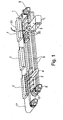
- FIG. 1 is a packaging machine that is suitable for a method according to the invention, shown and designated 100 in total.
- a corresponding packaging machine has a so-called Zweizug 10, which has two trains 1, 2.
- a first train 1 is loaded on a loading device 3 with packaged goods 30.
- the loading station 3 is located upstream of a production facility, not shown, a provides continuous product flow on packaged goods.
- a second train 2 is unloaded there, wherein the articles to be packaged are simultaneously pushed into a packaging board 7.
- the packaging cartons are provided by a conveyor belt 17.
- two traction drives 5, 6 are provided, which are able to move the trains 1, 2 independently of each other.
- the traction drives 5, 6 are also able to decelerate the conveyor belts.
- a load control device 31 ensures proper loading at the loading station 3. This may be, for example, an optical sensor.
- the operation of the packaging device 100 will be explained below.
- a first train 1, which is loaded at the loading station 3, has compartments which are loaded successively. For this purpose, train 1 is moved successively by a shed distance.
- the loading control device 31 ensures that a loading of all compartments is carried out. If train 1 is completely loaded, it is transported to the unloading station 2 at the highest possible speed and aligned there with a packaging board 7 which is provided on a belt 17.
- the unloading device 4 simultaneously pushes all the packaging articles into the carton. If train 2 is unloaded, it will cycle to the fastest possible speed Loading station to stand there ready for another loading.
- transport device 2 it must be ensured in a corresponding packaging machine that a continuous loading of transport devices 1, 2 can take place, since otherwise the upstream production machine comes to a standstill or overflows the packaging device. Even before the complete loading of the transport device 1 so an empty transport device (here transport device 2) must be available.
- FIG. 2 are speed and acceleration curves of transport devices of packaging machines according to the prior art shown.
- slave here is the catch-up transport device or the following train referred to, with "master” held at the loading station transport device or the front train.
- the graph labeled v master in FIG. 2 shows the cyclic speed change of the master at the loading station. This speed change corresponds to the timing of the master, which is used to load the individual compartments.
- a deceleration of the slave is initiated at 160 ms.
- the delay of the slave takes place approximately from the time 160 ms with a constant negative acceleration, ie with a deceleration rate.
- the deceleration is carried out approximately until the time 640 ms.
- the FIG. 2 the speed profile of the slave is shown. After initiating deceleration at 182 ms, the velocity of the slave slows down linearly. At the time 640 ms, the slave has arrived at the initially determined end position. However, since the master has moved on during the time since the initiation of the deceleration, the standstill position of the slave does not correspond to the required distance to the master, ie the distance between slave and master is too large. Therefore, a renewed acceleration of the slave is now initiated, which is made approximately up to the time 780 ms. Afterwards, the system decelerates again until the correct distance is finally set at 900 ms. As in the lower graph labeled InSync the FIG. 2 is shown, the time from the initiation of the first braking until reaching the correct position of the slave, t decel , 736 ms.
- FIG. 3 Figure 11 shows acceleration and deceleration characteristics of transport devices according to a preferred embodiment of the present invention.
- the movement of the master v master essentially corresponds to that of the FIG. 2
- the acceleration course of the slave a slave differs from that of the FIG. 2 since an adaptive adjustment of the braking is carried out according to the proposed method.
- the distance to the master is measured continuously and the deceleration adjusted to this distance.
- this adaptation is expressed in a wavy course of the graph of the delay a slave .
- the resulting speed change of the slave is shown in the upper graph and denoted by v slave .
- FIG. 3 can be seen that when using the method according to the invention, the delay time from the initiation of braking until the correct position t decel is only 610 ms.
- FIG. 4 the method according to the invention is illustrated according to a preferred embodiment in a speed-time diagram.
- the kink 41 in the course of the speed of the slave v slave corresponds to that of the Figures 2 and 3 when initiating the delay. From the time corresponding to the initiation of the delay 41, the delay takes place at a first deceleration rate ra 1 .
- the time interval between t 1 and t 2 and between t 2 and t 3 corresponds to a cycle time rt cyc of the device.
- the master moves at a speed v master . Due to the speed difference and the time difference between the points rv M1 and rv M2 results in an area that in the FIG. 4 hatched and labeled r ⁇ s.
- the slave has a speed rv S2 .
- the distance of the slave to the master is now determined and adapted to this an adapted Brake rate ra 2 calculated.
- This adjusted braking rate ra 2 is now used for an adapted braking, illustrated in the figure by the dashed line between the times t 2 and t 3 .
Landscapes
- Engineering & Computer Science (AREA)
- Human Computer Interaction (AREA)
- Manufacturing & Machinery (AREA)
- Physics & Mathematics (AREA)
- General Physics & Mathematics (AREA)
- Automation & Control Theory (AREA)
- Control Of Conveyors (AREA)
- Mechanical Control Devices (AREA)
- Electric Propulsion And Braking For Vehicles (AREA)
- Warehouses Or Storage Devices (AREA)
Claims (10)
- Procédé de fonctionnement d'une machine à emballer dotée d'au moins deux unités de transport mobiles (1, 2) disposées de manière périodique qui sont chargées de produit à emballer au niveau d'un dispositif de chargement (3), sont déplacées jusqu'à un dispositif de déchargement (4) et sont déchargées au niveau du dispositif de déchargement (4), une deuxième unité de transport (2) parmi les au moins deux unités de transport (1, 2) étant déplacée à une deuxième vitesse de déplacement (vslave) en direction d'une première unité de transport (1) parmi les au moins deux unités de transport (1, 2) et étant amenée à une distance prédéterminée par rapport à la première unité de transport (1) par freinage à un taux de freinage (ra1, ra2),
caractérisé en ce que
le taux de freinage (ra1, ra2) est déterminé à nouveau au moins une fois en fonction d'une distance de la deuxième unité de transport (2) par rapport à la première unité de transport (1) pendant le déplacement de la deuxième unité de transport. - Procédé selon la revendication 1, dans lequel la première unité de transport (1) se déplace au moins par intermittence à une première vitesse de déplacement (vmaster).
- Procédé selon la revendication 2, dans lequel le sens de déplacement de la première unité de transport (1) correspond au sens de déplacement de la deuxième unité de transport (2).
- Procédé selon l'une quelconque des revendications précédentes, dans lequel la distance prédéterminée est nulle.
- Procédé selon l'une quelconque des revendications précédentes, dans lequel, pendant le chargement de la première unité de transport (1), la deuxième unité de transport (9) est disposée en amont à la distance prédéterminée par rapport à la première unité de transport (1) par le freinage au taux de freinage (ra1, ra2) et est également chargée après le chargement de la première unité de transport (1).
- Procédé selon l'une quelconque des revendications précédentes, caractérisé par les étapes suivantes :a) déterminer une distance de freinage initiale de la deuxième unité de transport (2) à l'aide d'un taux de freinage initial (ra1),b) déterminer la distance instantanée de la première unité de transport (1) par rapport à la deuxième unité de transport (2),c) déterminer une première distance à partir de la distance instantanée déterminée à l'étape b) et de la distance prédéterminée,d) comparer la distance de freinage initiale déterminée à l'étape a) à la première distance déterminée à l'étape c),e) déclencher un freinage de la deuxième unité de transport au taux de freinage initial (ra1) si la distance de freinage déterminée à l'étape a) est supérieure ou égale à la première distance déterminée à l'étape c), ou répéter les étapes b) à d) après un premier intervalle de temps si la distance de freinage initiale déterminée à l'étape b) est inférieure à la première distance déterminée à l'étape c),f) déterminer à nouveau la distance instantanée de la première unité de transport par rapport à la deuxième unité pendant le freinage,g) déterminer une deuxième distance à partir de la distance instantanée déterminée à l'étape f) et de la distance prédéterminée,h) déterminer un taux de freinage adapté (ra2) à l'aide d'une distance de freinage adaptée de la deuxième unité de transport, la distance de freinage adaptée correspondant à la deuxième distance déterminée à l'étape g),i) modifier le freinage en utilisant le taux de freinage adapté (ra2) déterminé à l'étape h),j) répéter les étapes f) à i) après un deuxième intervalle de temps.
- Procédé selon la revendication 6, dans lequel le premier et/ou le deuxième intervalle de temps sont nuls et/ou correspondent à au moins un intervalle d'interrogation.
- Machine à emballer (100), qui comprend au moins deux unités de transport (1, 2), au moins un dispositif de chargement (3) pour le chargement des unités de transport (1, 2) et au moins un dispositif de déchargement (4) pour le déchargement des unités de transport (1, 2), des moyens d'entraînement (5, 6) pour transporter périodiquement les unités de transport et des moyens de freinage (5, 6) pour freiner au moins une unité de transport (1, 2) conformément à un procédé selon les revendications 1 à 7.
- Programme informatique comprenant des moyens de code de programme afin de mettre en oeuvre toutes les étapes d'un procédé selon l'une des revendications 1 à 7 lorsque le programme informatique est exécuté sur un ordinateur ou une unité de calcul correspondante.
- Produit-programme informatique comprenant des moyens de code de programme qui sont enregistrés sur un support de données lisible par ordinateur afin de mettre en oeuvre toutes les étapes d'un procédé selon l'une des revendications 1 à 7 lorsque les moyens de code de programme sont exécutés sur un ordinateur ou une unité de calcul correspondante.
Applications Claiming Priority (1)
| Application Number | Priority Date | Filing Date | Title |
|---|---|---|---|
| DE200810063190 DE102008063190A1 (de) | 2008-12-29 | 2008-12-29 | Verfahren zum Betrieb einer Vorrichtung mit wenigstens zwei bewegbaren Einheiten |
Publications (3)
| Publication Number | Publication Date |
|---|---|
| EP2202597A2 EP2202597A2 (fr) | 2010-06-30 |
| EP2202597A3 EP2202597A3 (fr) | 2011-03-09 |
| EP2202597B1 true EP2202597B1 (fr) | 2012-11-14 |
Family
ID=42091543
Family Applications (1)
| Application Number | Title | Priority Date | Filing Date |
|---|---|---|---|
| EP20090015458 Not-in-force EP2202597B1 (fr) | 2008-12-29 | 2009-12-15 | Procédé de fonctionnement d'une machine à emballer dotée d'au moins deux unités mobiles et machine à emballer |
Country Status (2)
| Country | Link |
|---|---|
| EP (1) | EP2202597B1 (fr) |
| DE (1) | DE102008063190A1 (fr) |
Families Citing this family (2)
| Publication number | Priority date | Publication date | Assignee | Title |
|---|---|---|---|---|
| DE102017215525A1 (de) | 2017-09-05 | 2019-03-07 | Robert Bosch Gmbh | Sensoreinrichtung zur Integration in eine Industrieanlage, Messeinrichtungsergänzungseinheit, Industrieanlage und Verfahren |
| CN114402811B (zh) * | 2021-12-31 | 2024-04-30 | 广州极飞科技股份有限公司 | 一种间歇静止作业机构、设备及方法 |
Family Cites Families (5)
| Publication number | Priority date | Publication date | Assignee | Title |
|---|---|---|---|---|
| DE69011744T2 (de) * | 1989-06-01 | 1995-03-23 | Mazda Motor | Förderer mit Linearmotor. |
| EP0957283A3 (fr) * | 1998-05-12 | 2000-07-05 | Fa. SYSTEC EPE | Articulation de suivi |
| JP3452899B2 (ja) * | 2000-12-28 | 2003-10-06 | ファナック株式会社 | 同期制御方法及び装置 |
| JP4799761B2 (ja) * | 2001-05-28 | 2011-10-26 | オンセミコンダクター・トレーディング・リミテッド | ステッピングモータの制御方法 |
| US7134258B2 (en) * | 2001-12-05 | 2006-11-14 | R.A. Jones & Co. Inc. | Packaging apparatus and methods |
-
2008
- 2008-12-29 DE DE200810063190 patent/DE102008063190A1/de not_active Withdrawn
-
2009
- 2009-12-15 EP EP20090015458 patent/EP2202597B1/fr not_active Not-in-force
Also Published As
| Publication number | Publication date |
|---|---|
| EP2202597A3 (fr) | 2011-03-09 |
| EP2202597A2 (fr) | 2010-06-30 |
| DE102008063190A1 (de) | 2010-07-01 |
Similar Documents
| Publication | Publication Date | Title |
|---|---|---|
| EP2106376B1 (fr) | Piste intelligente de transport et de retenue | |
| EP2942167B1 (fr) | Procédé et dispositif de préparation d'aliments de différentes sortes | |
| EP2097324B1 (fr) | Procede pour commander le transfert d'une pile de produits dans une machine d'emballage | |
| EP3715287A1 (fr) | Dispositif de transport de produits | |
| EP1595797B1 (fr) | Machine d'emballage et procédé d'alimentation de récipients dans une machine d'emballage | |
| DE102005063193B4 (de) | Vorrichtung und Verfahren zum Gruppieren von Stückgut | |
| AT508865B1 (de) | Fördereinrichtung und verfahren zum betrieb einer fördereinrichtung | |
| EP2818421A1 (fr) | Machine de fermeture de barquettes avec une alimentation de barquettes et procédé pour une installation d'emballage | |
| EP3924278B1 (fr) | Dispositif de transport pour le rangement d'objets sans espacement et sans pression ou avec faible pression, et son procédé de fonctionnement | |
| EP3210896A2 (fr) | Machine d'emballage par emboutissage | |
| EP3315267B1 (fr) | Procédé d'optimisation de profils de mouvement, procédé de fourniture de profils de mouvements, dispositif de commande, installation et produit-programme informatique | |
| DE102012109316A1 (de) | Übergabevorrichtung sowie Transportvorrichtung für Güter sowie Verfahren zum Betreiben einer Transportvorrichtung | |
| EP2545418B1 (fr) | Procédé de détermination d'un tracé de courbe nominale optimisé dans une machine à plusieurs axes pour le traitement volant de produit transporté | |
| WO2023118442A1 (fr) | Dispositif de transport | |
| EP3025587B1 (fr) | Dispositif et procédé destinés au transfert de portions de saucisses | |
| EP0527542A1 (fr) | Système de convoyeurs alimenté par plusieurs couloirs | |
| EP2202597B1 (fr) | Procédé de fonctionnement d'une machine à emballer dotée d'au moins deux unités mobiles et machine à emballer | |
| DE102017207255A1 (de) | Verfahren zum Befüllen von Behältnissen | |
| EP3455434A1 (fr) | Dispositif et procédé pour garer un véhicule | |
| EP3947215B1 (fr) | Procédé et système de transport pour une détermination de position améliorée d'un objet transporté sur le système de transport | |
| EP2452904B1 (fr) | Dispositif de transport de piles de documents, notamment de documents de sécurité, vers des stations de reliure | |
| EP1911696B1 (fr) | Dispositif destiné à remplir des trous | |
| EP3150344B1 (fr) | Dispositif d'alignement pour aligner des pièces à usiner et machine d'usinage | |
| EP3283412B1 (fr) | Procédé et système de transport de commande d'un flux de récipients | |
| EP0577021A1 (fr) | Convoyeur d'alimentation pour alimenter des colis de détail sur un convoyeur de réception |
Legal Events
| Date | Code | Title | Description |
|---|---|---|---|
| PUAI | Public reference made under article 153(3) epc to a published international application that has entered the european phase |
Free format text: ORIGINAL CODE: 0009012 |
|
| AK | Designated contracting states |
Kind code of ref document: A2 Designated state(s): AT BE BG CH CY CZ DE DK EE ES FI FR GB GR HR HU IE IS IT LI LT LU LV MC MK MT NL NO PL PT RO SE SI SK SM TR |
|
| AX | Request for extension of the european patent |
Extension state: AL BA RS |
|
| PUAL | Search report despatched |
Free format text: ORIGINAL CODE: 0009013 |
|
| AK | Designated contracting states |
Kind code of ref document: A3 Designated state(s): AT BE BG CH CY CZ DE DK EE ES FI FR GB GR HR HU IE IS IT LI LT LU LV MC MK MT NL NO PL PT RO SE SI SK SM TR |
|
| AX | Request for extension of the european patent |
Extension state: AL BA RS |
|
| 17P | Request for examination filed |
Effective date: 20110909 |
|
| 17Q | First examination report despatched |
Effective date: 20111114 |
|
| GRAP | Despatch of communication of intention to grant a patent |
Free format text: ORIGINAL CODE: EPIDOSNIGR1 |
|
| GRAS | Grant fee paid |
Free format text: ORIGINAL CODE: EPIDOSNIGR3 |
|
| GRAA | (expected) grant |
Free format text: ORIGINAL CODE: 0009210 |
|
| AK | Designated contracting states |
Kind code of ref document: B1 Designated state(s): AT BE BG CH CY CZ DE DK EE ES FI FR GB GR HR HU IE IS IT LI LT LU LV MC MK MT NL NO PL PT RO SE SI SK SM TR |
|
| REG | Reference to a national code |
Ref country code: GB Ref legal event code: FG4D Free format text: NOT ENGLISH |
|
| REG | Reference to a national code |
Ref country code: CH Ref legal event code: EP Ref country code: AT Ref legal event code: REF Ref document number: 584291 Country of ref document: AT Kind code of ref document: T Effective date: 20121115 |
|
| REG | Reference to a national code |
Ref country code: IE Ref legal event code: FG4D Free format text: LANGUAGE OF EP DOCUMENT: GERMAN |
|
| REG | Reference to a national code |
Ref country code: DE Ref legal event code: R096 Ref document number: 502009005356 Country of ref document: DE Effective date: 20130110 |
|
| REG | Reference to a national code |
Ref country code: NL Ref legal event code: T3 |
|
| REG | Reference to a national code |
Ref country code: LT Ref legal event code: MG4D |
|
| PG25 | Lapsed in a contracting state [announced via postgrant information from national office to epo] |
Ref country code: NO Free format text: LAPSE BECAUSE OF FAILURE TO SUBMIT A TRANSLATION OF THE DESCRIPTION OR TO PAY THE FEE WITHIN THE PRESCRIBED TIME-LIMIT Effective date: 20130214 Ref country code: SE Free format text: LAPSE BECAUSE OF FAILURE TO SUBMIT A TRANSLATION OF THE DESCRIPTION OR TO PAY THE FEE WITHIN THE PRESCRIBED TIME-LIMIT Effective date: 20121114 Ref country code: FI Free format text: LAPSE BECAUSE OF FAILURE TO SUBMIT A TRANSLATION OF THE DESCRIPTION OR TO PAY THE FEE WITHIN THE PRESCRIBED TIME-LIMIT Effective date: 20121114 Ref country code: LT Free format text: LAPSE BECAUSE OF FAILURE TO SUBMIT A TRANSLATION OF THE DESCRIPTION OR TO PAY THE FEE WITHIN THE PRESCRIBED TIME-LIMIT Effective date: 20121114 Ref country code: HR Free format text: LAPSE BECAUSE OF FAILURE TO SUBMIT A TRANSLATION OF THE DESCRIPTION OR TO PAY THE FEE WITHIN THE PRESCRIBED TIME-LIMIT Effective date: 20121114 Ref country code: ES Free format text: LAPSE BECAUSE OF FAILURE TO SUBMIT A TRANSLATION OF THE DESCRIPTION OR TO PAY THE FEE WITHIN THE PRESCRIBED TIME-LIMIT Effective date: 20130225 |
|
| PG25 | Lapsed in a contracting state [announced via postgrant information from national office to epo] |
Ref country code: GR Free format text: LAPSE BECAUSE OF FAILURE TO SUBMIT A TRANSLATION OF THE DESCRIPTION OR TO PAY THE FEE WITHIN THE PRESCRIBED TIME-LIMIT Effective date: 20130215 Ref country code: LV Free format text: LAPSE BECAUSE OF FAILURE TO SUBMIT A TRANSLATION OF THE DESCRIPTION OR TO PAY THE FEE WITHIN THE PRESCRIBED TIME-LIMIT Effective date: 20121114 Ref country code: PL Free format text: LAPSE BECAUSE OF FAILURE TO SUBMIT A TRANSLATION OF THE DESCRIPTION OR TO PAY THE FEE WITHIN THE PRESCRIBED TIME-LIMIT Effective date: 20121114 Ref country code: PT Free format text: LAPSE BECAUSE OF FAILURE TO SUBMIT A TRANSLATION OF THE DESCRIPTION OR TO PAY THE FEE WITHIN THE PRESCRIBED TIME-LIMIT Effective date: 20130314 Ref country code: SI Free format text: LAPSE BECAUSE OF FAILURE TO SUBMIT A TRANSLATION OF THE DESCRIPTION OR TO PAY THE FEE WITHIN THE PRESCRIBED TIME-LIMIT Effective date: 20121114 |
|
| BERE | Be: lapsed |
Owner name: ROBERT BOSCH G.M.B.H. Effective date: 20121231 |
|
| PG25 | Lapsed in a contracting state [announced via postgrant information from national office to epo] |
Ref country code: SK Free format text: LAPSE BECAUSE OF FAILURE TO SUBMIT A TRANSLATION OF THE DESCRIPTION OR TO PAY THE FEE WITHIN THE PRESCRIBED TIME-LIMIT Effective date: 20121114 Ref country code: DK Free format text: LAPSE BECAUSE OF FAILURE TO SUBMIT A TRANSLATION OF THE DESCRIPTION OR TO PAY THE FEE WITHIN THE PRESCRIBED TIME-LIMIT Effective date: 20121114 Ref country code: BG Free format text: LAPSE BECAUSE OF FAILURE TO SUBMIT A TRANSLATION OF THE DESCRIPTION OR TO PAY THE FEE WITHIN THE PRESCRIBED TIME-LIMIT Effective date: 20130214 Ref country code: MC Free format text: LAPSE BECAUSE OF NON-PAYMENT OF DUE FEES Effective date: 20121231 Ref country code: EE Free format text: LAPSE BECAUSE OF FAILURE TO SUBMIT A TRANSLATION OF THE DESCRIPTION OR TO PAY THE FEE WITHIN THE PRESCRIBED TIME-LIMIT Effective date: 20121114 Ref country code: CZ Free format text: LAPSE BECAUSE OF FAILURE TO SUBMIT A TRANSLATION OF THE DESCRIPTION OR TO PAY THE FEE WITHIN THE PRESCRIBED TIME-LIMIT Effective date: 20121114 |
|
| PG25 | Lapsed in a contracting state [announced via postgrant information from national office to epo] |
Ref country code: RO Free format text: LAPSE BECAUSE OF FAILURE TO SUBMIT A TRANSLATION OF THE DESCRIPTION OR TO PAY THE FEE WITHIN THE PRESCRIBED TIME-LIMIT Effective date: 20121114 |
|
| PLBE | No opposition filed within time limit |
Free format text: ORIGINAL CODE: 0009261 |
|
| STAA | Information on the status of an ep patent application or granted ep patent |
Free format text: STATUS: NO OPPOSITION FILED WITHIN TIME LIMIT |
|
| REG | Reference to a national code |
Ref country code: IE Ref legal event code: MM4A |
|
| REG | Reference to a national code |
Ref country code: FR Ref legal event code: ST Effective date: 20130830 |
|
| PG25 | Lapsed in a contracting state [announced via postgrant information from national office to epo] |
Ref country code: BE Free format text: LAPSE BECAUSE OF NON-PAYMENT OF DUE FEES Effective date: 20121231 |
|
| 26N | No opposition filed |
Effective date: 20130815 |
|
| PG25 | Lapsed in a contracting state [announced via postgrant information from national office to epo] |
Ref country code: IE Free format text: LAPSE BECAUSE OF NON-PAYMENT OF DUE FEES Effective date: 20121215 |
|
| PG25 | Lapsed in a contracting state [announced via postgrant information from national office to epo] |
Ref country code: FR Free format text: LAPSE BECAUSE OF NON-PAYMENT OF DUE FEES Effective date: 20130114 Ref country code: MT Free format text: LAPSE BECAUSE OF FAILURE TO SUBMIT A TRANSLATION OF THE DESCRIPTION OR TO PAY THE FEE WITHIN THE PRESCRIBED TIME-LIMIT Effective date: 20121114 Ref country code: CY Free format text: LAPSE BECAUSE OF FAILURE TO SUBMIT A TRANSLATION OF THE DESCRIPTION OR TO PAY THE FEE WITHIN THE PRESCRIBED TIME-LIMIT Effective date: 20121114 |
|
| REG | Reference to a national code |
Ref country code: DE Ref legal event code: R097 Ref document number: 502009005356 Country of ref document: DE Effective date: 20130815 |
|
| PG25 | Lapsed in a contracting state [announced via postgrant information from national office to epo] |
Ref country code: TR Free format text: LAPSE BECAUSE OF FAILURE TO SUBMIT A TRANSLATION OF THE DESCRIPTION OR TO PAY THE FEE WITHIN THE PRESCRIBED TIME-LIMIT Effective date: 20121114 |
|
| PG25 | Lapsed in a contracting state [announced via postgrant information from national office to epo] |
Ref country code: LU Free format text: LAPSE BECAUSE OF NON-PAYMENT OF DUE FEES Effective date: 20121215 Ref country code: SM Free format text: LAPSE BECAUSE OF FAILURE TO SUBMIT A TRANSLATION OF THE DESCRIPTION OR TO PAY THE FEE WITHIN THE PRESCRIBED TIME-LIMIT Effective date: 20121114 |
|
| PG25 | Lapsed in a contracting state [announced via postgrant information from national office to epo] |
Ref country code: HU Free format text: LAPSE BECAUSE OF FAILURE TO SUBMIT A TRANSLATION OF THE DESCRIPTION OR TO PAY THE FEE WITHIN THE PRESCRIBED TIME-LIMIT Effective date: 20091215 |
|
| PG25 | Lapsed in a contracting state [announced via postgrant information from national office to epo] |
Ref country code: MK Free format text: LAPSE BECAUSE OF FAILURE TO SUBMIT A TRANSLATION OF THE DESCRIPTION OR TO PAY THE FEE WITHIN THE PRESCRIBED TIME-LIMIT Effective date: 20121114 |
|
| PG25 | Lapsed in a contracting state [announced via postgrant information from national office to epo] |
Ref country code: IS Free format text: LAPSE BECAUSE OF FAILURE TO SUBMIT A TRANSLATION OF THE DESCRIPTION OR TO PAY THE FEE WITHIN THE PRESCRIBED TIME-LIMIT Effective date: 20121114 |
|
| PGFP | Annual fee paid to national office [announced via postgrant information from national office to epo] |
Ref country code: AT Payment date: 20201215 Year of fee payment: 12 Ref country code: CH Payment date: 20201222 Year of fee payment: 12 Ref country code: GB Payment date: 20201222 Year of fee payment: 12 |
|
| PGFP | Annual fee paid to national office [announced via postgrant information from national office to epo] |
Ref country code: NL Payment date: 20201217 Year of fee payment: 12 |
|
| PGFP | Annual fee paid to national office [announced via postgrant information from national office to epo] |
Ref country code: IT Payment date: 20201230 Year of fee payment: 12 |
|
| PGFP | Annual fee paid to national office [announced via postgrant information from national office to epo] |
Ref country code: DE Payment date: 20210217 Year of fee payment: 12 |
|
| REG | Reference to a national code |
Ref country code: DE Ref legal event code: R119 Ref document number: 502009005356 Country of ref document: DE |
|
| REG | Reference to a national code |
Ref country code: CH Ref legal event code: PL |
|
| REG | Reference to a national code |
Ref country code: NL Ref legal event code: MM Effective date: 20220101 |
|
| REG | Reference to a national code |
Ref country code: AT Ref legal event code: MM01 Ref document number: 584291 Country of ref document: AT Kind code of ref document: T Effective date: 20211215 |
|
| GBPC | Gb: european patent ceased through non-payment of renewal fee |
Effective date: 20211215 |
|
| PG25 | Lapsed in a contracting state [announced via postgrant information from national office to epo] |
Ref country code: NL Free format text: LAPSE BECAUSE OF NON-PAYMENT OF DUE FEES Effective date: 20220101 |
|
| PG25 | Lapsed in a contracting state [announced via postgrant information from national office to epo] |
Ref country code: GB Free format text: LAPSE BECAUSE OF NON-PAYMENT OF DUE FEES Effective date: 20211215 Ref country code: DE Free format text: LAPSE BECAUSE OF NON-PAYMENT OF DUE FEES Effective date: 20220701 Ref country code: AT Free format text: LAPSE BECAUSE OF NON-PAYMENT OF DUE FEES Effective date: 20211215 |
|
| PG25 | Lapsed in a contracting state [announced via postgrant information from national office to epo] |
Ref country code: LI Free format text: LAPSE BECAUSE OF NON-PAYMENT OF DUE FEES Effective date: 20211231 Ref country code: CH Free format text: LAPSE BECAUSE OF NON-PAYMENT OF DUE FEES Effective date: 20211231 |
|
| PG25 | Lapsed in a contracting state [announced via postgrant information from national office to epo] |
Ref country code: IT Free format text: LAPSE BECAUSE OF NON-PAYMENT OF DUE FEES Effective date: 20211215 |