EP2202682A1 - Procédé de génération d'image, dispositif associé, son programme et support d'enregistrement du programme - Google Patents
Procédé de génération d'image, dispositif associé, son programme et support d'enregistrement du programme Download PDFInfo
- Publication number
- EP2202682A1 EP2202682A1 EP08839078A EP08839078A EP2202682A1 EP 2202682 A1 EP2202682 A1 EP 2202682A1 EP 08839078 A EP08839078 A EP 08839078A EP 08839078 A EP08839078 A EP 08839078A EP 2202682 A1 EP2202682 A1 EP 2202682A1
- Authority
- EP
- European Patent Office
- Prior art keywords
- image
- color signal
- unit
- corresponding point
- threshold
- Prior art date
- Legal status (The legal status is an assumption and is not a legal conclusion. Google has not performed a legal analysis and makes no representation as to the accuracy of the status listed.)
- Withdrawn
Links
Images


Classifications
-
- G—PHYSICS
- G06—COMPUTING OR CALCULATING; COUNTING
- G06T—IMAGE DATA PROCESSING OR GENERATION, IN GENERAL
- G06T5/00—Image enhancement or restoration
- G06T5/50—Image enhancement or restoration using two or more images, e.g. averaging or subtraction
-
- G—PHYSICS
- G06—COMPUTING OR CALCULATING; COUNTING
- G06T—IMAGE DATA PROCESSING OR GENERATION, IN GENERAL
- G06T15/00—Three-dimensional [3D] image rendering
- G06T15/10—Geometric effects
- G06T15/20—Perspective computation
- G06T15/205—Image-based rendering
-
- H—ELECTRICITY
- H04—ELECTRIC COMMUNICATION TECHNIQUE
- H04N—PICTORIAL COMMUNICATION, e.g. TELEVISION
- H04N1/00—Scanning, transmission or reproduction of documents or the like, e.g. facsimile transmission; Details thereof
- H04N1/46—Colour picture communication systems
- H04N1/56—Processing of colour picture signals
- H04N1/60—Colour correction or control
- H04N1/603—Colour correction or control controlled by characteristics of the picture signal generator or the picture reproducer
- H04N1/6052—Matching two or more picture signal generators or two or more picture reproducers
- H04N1/6055—Matching two or more picture signal generators or two or more picture reproducers using test pattern analysis
-
- G—PHYSICS
- G06—COMPUTING OR CALCULATING; COUNTING
- G06T—IMAGE DATA PROCESSING OR GENERATION, IN GENERAL
- G06T2207/00—Indexing scheme for image analysis or image enhancement
- G06T2207/10—Image acquisition modality
- G06T2207/10016—Video; Image sequence
-
- G—PHYSICS
- G06—COMPUTING OR CALCULATING; COUNTING
- G06T—IMAGE DATA PROCESSING OR GENERATION, IN GENERAL
- G06T2207/00—Indexing scheme for image analysis or image enhancement
- G06T2207/10—Image acquisition modality
- G06T2207/10024—Color image
-
- G—PHYSICS
- G06—COMPUTING OR CALCULATING; COUNTING
- G06T—IMAGE DATA PROCESSING OR GENERATION, IN GENERAL
- G06T2207/00—Indexing scheme for image analysis or image enhancement
- G06T2207/20—Special algorithmic details
- G06T2207/20212—Image combination
- G06T2207/20221—Image fusion; Image merging
Definitions
- the present invention relates to a technique for generating image information for color signals by using a plurality of images.
- Priority is claimed on Japanese Patent Application No. 2007-267541, filed October 15, 2007 , the contents of which are incorporated herein by reference.
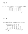
- FIG. 7 is a diagram showing an example of camera arrangement having a straight-line alignment
- Fig. 8 is a diagram showing another example of camera arrangement having a planar arrangement
- Fig. 9 is a diagram showing another example of camera arrangement having an arc arrangement
- Fig. 10 is a diagram showing another example of camera arrangement having a spherical arrangement.
- the multi-view imaging systems for imaging a scene in different directions have been developed.
- the camera arrangement has various forms such as a one-dimensional arrangement on a straight line as shown in Fig. 7 , a two-dimensional arrangement on a plane as shown in Fig. 8 , an arc arrangement as shown in Fig. 9 , or a spherical arrangement as shown in Fig. 10 .
- Using such multi-view imaging systems makes it possible to archive video scenes in many directions.
- image synthesis for generating image information at a virtual camera position (at which imaging is not performed) by using camera images obtained by multi-view imaging.
- image synthesis it is assumed that a camera parameter which indicates the spatial direction in which the original video image was obtained is known.
- the image synthesis can be performed by various methods. For example, there is a method of performing synthesis by estimating depth information. First, disparity information is obtained by searching corresponding points between original video images, and depth information of the relevant scene is estimated based on the disparity information. Then, depth information at the virtual camera position is estimated, and corresponding image information is generated using image information of the original cameras (see Non-Patent Document 1).
- a plurality of camera images are used for estimating a three-dimensional model information of an object which is present in the relevant scene, and an image of the model projected from the virtual camera position is generated (see Non-Patent Document 3).
- imaging is generally performed using image signals having a Bayer arrangement, and the Bayer arrangement is subjected to demosaicing to obtain RGB signals or YUV signals (i.e., luminance signal Y and chrominance signals U and V).
- Demosaicing is a process of estimating the three color components (RGB) of each pixel position, based on an R, G, or B signal assigned to each pixel position obtained using the Bayer arrangement (see Non-Patent Document 4).
- demosaicing corresponds to increasing of the resolution of the signal of each color component from a low value to a high value, it may be performed together with a super-resolution technique (see Non-Patent Document 5).
- cameras having the same resolution are generally used, however, those having different resolutions may be used. It is possible to reduce the amount of obtained image information by using a combination of a camera having a high resolution and a camera having a low resolution.
- the cameras may have different focusing positions or viewing angles. In such a case, even when each image signal to be obtained has the same resolution, each area which is actually imaged has an individual resolution.
- an enlarging method of applying an up-sampling filter to each image signal in an image having a low resolution and a super-resolution method are known.
- an image signal is obtained by applying an appropriate filter to image signals in a peripheral area.
- information of a plurality of images having the same resolution, which were sequentially obtained is used (see Non-Patent Document 6).
- a target image that is, each pixel position of a target to be generated is defined in advance.
- a corresponding relationship between the obtained images is estimated, and each image signal obtained by imaging is assigned to the corresponding target pixel position, thereby obtaining image information having a high resolution.
- Fig. 11 shows a Munsell color space invented by Munsell.
- colors are represented using hue, value, and chroma.
- the "hue” indicates tint, and has five basic hues of red (R), yellow (Y), green (G), blue (B), and purple (P). That is, 10 hues are defined together with intermediate hues such as yellow-red (YR), yellow-green (GY), blue-green (BG), blue-purple (PB), and red-purple (RP).
- the "value” indicates brightness, where 0 is assigned to ideal black for complete absorption, and 10 is assigned to ideal white for complete reflection. Between them, 10 levels are defined at sensibly equal intervals.
- the chroma indicates vividness.
- the Munsell symbol is represented as HV/C (hue ⁇ value / chroma).
- HV/C hue ⁇ value / chroma
- the hue is regularly arranged along a circumference so as to form a hue circle. For the chroma, the farther from the center, the higher the chroma, which produces a more vivid color.
- a CIE L * a * b * space or a CIE L * u * v * space has been proposed.
- Non-Patent Document 1 Keita Takahashi and Takeshi Naemura, "Layered Light-Field Rendering with Focus Measurement", EURASIP Signal Processing: Image Communication, vol.21, no.6, pp.519-530 (2006.7 ).
- Non-Patent Document 2 M. Droese, T. Fujii and M. Tanimoto,"Ray-Space Interpolation Constraining Smooth Disparities Based On Loopy Belief Propagation", Proc. of IWSSIP2004, pp.247-250, Poznan, Poland, Sept. 2004 .
- Non-Patent Document 3 Takashi Matsuyama, Takeshi Takai, Xiaojunn Wu, and Shohei Nobuhara, "Generation, Editing, and Visualization of 3D Video", Proceedings of The Virtual Reality Society of Japan, Vol.7, No.4, pp. 521-532, 2002.12 .
- Non-Patent Document 4 I. Tsubaki and K. Aizawa, "Demosaicing method from pixel mixture image", Forum on Information Science and Technology, pp. 219-222, Sep. 2003 .
- Non-Patent Document 5 Tomomasa Goto and Masatoshi Okutomi, "High Resolution Color Image Reconstruction Using Raw Data of a Single Imaging Chip", IPSJ Transactions on Computer Vision and Image Media, Vol. 45, No. SIG 8(CVIM 9), pp. 15-25, 2004 .
- Non-Patent Document 6 Masayuki Tanaka and Masatoshi Okutomi, "A Fast Algorithm for Reconstruction-Based Super-Resolution and Its Accuracy Evaluation", Proceedings of IEICE, D-II vol. J88-D-II, No. 11, pp. 2200-2209, 2005 .
- the present invention relates to using a plurality of cameras having different resolutions, and an object of the present invention is to provide a method for restoring high-frequency color signal information which a low-resolution image does not have, thereby reducing degradation in subjective image quality.
- both an image having a high resolution and an image having a low resolution are present. Even when using cameras having the same resolution, the amount of information can be reduced by decreasing the resolution of a part of the cameras, which is preferable for the compression of a multi-view image. Also in such a case, both an image having a high resolution and an image having a low resolution are present.
- the present invention assumes a case in which each color signal has an individual resolution.
- a plurality of images have the same resolution for the Y signal, but have different resolutions for the U signal or the V signal.
- image information of another color signal having a low resolution misses a high-frequency component. Therefore, image information obtained at a camera position corresponding to a low resolution has a lower subjective image quality than image information obtained at a camera position corresponding to a high resolution.
- the present invention solves the above problem, and provides a technique for restoring high-frequency color signal information which a low-resolution image does not have, thereby reducing degradation in subjective image quality.
- the total amount of image information to be processed can be reduced by imaging a scene using a plurality of cameras, each of which has an individual number of colors, in comparison with processing all of the relevant colors. Therefore, the amount of code of a multi-view video image can be considerably reduced by reducing the number of colors for a part of video signals in the multi-view video image.
- the number of colors may be "three" of RGB or the like.
- the number of colors may be "three" of RGB or the like.
- the present invention solves such a problem by providing a technical device for restoring missing color information in a part of video signals by using another video signal.
- a multi-view video image which does not have a constant number of colors is not handled.
- the object of the present invention is generated from a novel technical concept of handling a multi-view video image which does not have a constant number of colors.
- the present invention uses corresponding point information between pixels in a plurality of images so that color information of a target image is restored using color information obtained using another camera.
- the present invention has specific distinctive features as follows.
- the present invention provides an image generation method for generating image information of a color signal Y of an image A by using a color signal X of image A, and color signal X and color signal Y of an image B, the method executing:
- image information of another color signal of a desired image can be generated using information of a color signal included in another image. If an image signal corresponding to a target pixel position for the generation, the relevant image information can be generated by means of interpolation using already-generated peripheral image signals having a high resolution, thereby preventing missing of image information.
- corresponding point information may be provided as input data, or each corresponding point may be searched for by using image information.
- depth information or geometric information of the relevant scene may be estimated in advance, and then corresponding points between the images may be estimated.
- the absolute value of each difference between corresponding pixels may be computed.
- a point which produces the minimum value may be estimated to be a corresponding point.
- the minimum absolute value is larger than the threshold, it may be estimated that there is no corresponding point. It is also preferable to store the threshold together with the relevant image information of an original color signal by means of filing. When generating image information of another color signal using the stored image information of the original color signal, the same image can always be generated by using the threshold included in the relevant file.
- image information of a color signal of a desired camera can be generated using an image of another camera.
- This method can be applied not only to a multi-view image but also to a video image obtained by a single camera. That is, when frames in a video image have different color signals, image information of a color signal of a desired frame can be generated using a color signal of another frame.
- the above image generation method may further execute:
- the magnitude of degradation due to an error in the corresponding point estimation is measured in another color space, and a threshold used for corresponding point estimation can be determined while minimizing the degradation. If the magnitude of degradation is measured by means of mapping to another color space, the value, chroma, and hue of the Munsell color space are examples of a color space for the mapping. Degradation in the subjective image quality can be reduced by minimizing the degradation in the subjective image quality of the generated image.
- the threshold parameter can be used as explained below. After the threshold is estimated, the value is appended as a threshold parameter to original image information. For example, the threshold parameter is also stored in a file together with the original image and another relevant image. When reading the file, image information of a color signal of the original image can be generated based on the original image and the other image by using the above threshold parameter, where the image has a minimum degradation in the subjective image quality.
- the above image generation method may further execute:
- the magnitude of degradation due to an error in the corresponding point estimation is measured, and a threshold used for corresponding point estimation can be determined while minimizing the degradation.
- a threshold used for corresponding point estimation can be determined while minimizing the degradation.
- the obtained threshold parameter can be stored in a file.
- the present invention also provides image generation apparatuses which generates images in accordance with the above methods.
- image information obtained at a camera position using a color signal image information obtained using another color signal can be used for generating a color signal of the desired image information, thereby reducing degradation in the subjective image quality.
- a color signal X of an image A and color signals X and Y of a color signal B, the image being obtained using different cameras, are used for generating the color signal Y of image A.
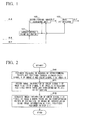
- Fig. 1 shows a general structure of the apparatus. That is, the image generation apparatus of the present embodiment has a corresponding point estimator 101 for estimating presence or absence of a point in color signal X of image B corresponding to each pixel position of color signal X of image A and also for estimating the position of the relevant corresponding point, a corresponding image assigning unit 102 for assigning, to color signal Y at each pixel position in image A for which the corresponding point estimator 101 estimates that there is a corresponding point, image information of the corresponding position in color signal Y of image B, and an image interpolator 103 for generating color signal Y at each pixel position in image A for which the corresponding point estimator 101 estimates that there is no corresponding point, by using the image information of color signal Y assigned by the corresponding image assigning unit 102.
- a corresponding point estimator 101 for estimating presence or absence of a point in color signal X of image B corresponding to each pixel position of color signal X of image A and also for estimating the
- the corresponding point estimator 101 uses camera parameters or a known matching technique for assuming one or more candidates of a pixel (in color signal X of image B) corresponding to each pixel in color signal X of image A, and computes an absolute value of the difference between each pair of corresponding pixels.
- the corresponding point estimator 102 estimates the point which produces the minimum value to be the corresponding point.
- the corresponding point estimator 102 estimates that there is no point corresponding to the relevant pixel in color signal X of image A.
- the image interpolator 103 generates the image information of color signal Y at each pixel position in color signal X of image A for which it is estimated that there is no corresponding point, by using the image information at pixel positions in color signal Y of image B, which was assigned due to an estimation result that there are corresponding points. More specifically, linear interpolation is performed in accordance with distances measured from the pixel positions to which the image information in image B was assigned.
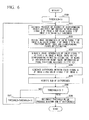
- Fig. 2 is a flowchart showing the operation.
- the corresponding point estimator 101 estimates the presence or absence of the corresponding points and positions thereof between image color signal X of image A and color signal X of image B (see step S10).
- the corresponding image assigning unit 102 assigns image information of the corresponding point in color signal Y of image B, as color signal Y of image A (see step S11).
- the image interpolator 103 generates image information by means of interpolation using the image information which was already assigned by the corresponding image assigning unit 102 (see step S12).
- Color signal Y of image A is generated by the above operation.
- the corresponding point estimator 101 computes the absolute value of each difference between the relevant pixels in the above operation.
- estimation may be performed using a block consisting of a plurality of pixels whose center pixel is the target pixel for estimation.
- a block consisting of a plurality of pixels whose center pixel is the target pixel for estimation.
- one or more candidates of a corresponding pixel in signal Y are assumed, and the total sum of absolute values of differences from a plurality of pixels which form a block and whose center is each candidate.
- the position of the candidate which produces the minimum value of the total sums may be estimated to be the corresponding point.
- the image interpolator 103 generates the relevant image information by means of linear interpolation in the above operation. However, the image information may be generated through a non-linear process. In either case, the image information is generated using the image information which was already assigned by the corresponding image assigning unit 102.
- color signal X of image A and color signals X and Y of image B are used for generating color signal Y of image A.
- color signal X of image A and color signals X and Y of image B which were obtained by a common camera at different times, may be used for generating color signal Y of image A.
- images A and B may have a plurality of signals other than color signal Y.
- An example in which images A and B have two other color signals (X and Z) will be shown below. The operation of the apparatus in this case will be explained while the structure is the same as above.
- the corresponding point estimator 101 estimates the presence or absence of the corresponding points and positions thereof between color signal X of image A and color signal X of image B as described above. To each position of color signal Y of image A for which the corresponding point estimator 101 estimates that there is a corresponding point, the corresponding image assigning unit 102 assigns image information of the corresponding position in color signal Y of image B. Similarly, the corresponding point estimator 101 estimates the presence or absence of the corresponding points and positions thereof between color signal Z of image A and color signal Z of image B.
- the corresponding image assigning unit 102 assigns image information of the corresponding position in color signal Y of image B.
- Color signal Y of Image A is generated by the above operation.
- a color signal X of an image A and color signals X and Y of a color signal B, the image being obtained using different cameras, are used for generating the color signal Y of image A.
- the generated image information is mapped into another color space so as to measure the degree of degradation, and to obtain a threshold for minimizing the degradation.
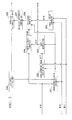
- Fig. 3 shows a general structure of the apparatus. That is, the image generation apparatus of the present embodiment has:
- the threshold setting unit 208 increases the threshold by increments of 10 from 10 to 50.
- the image A color converter 204 and the image B color converter 205 performs color space conversion into color signal M corresponding to the hue of the Munsell color space, where fixed values are assigned to the remaining color components (i.e., value and chroma).
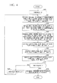
- Fig. 4 is a flowchart showing the operation.
- the threshold setting unit 208 sets the threshold to 10 (see step S20).
- the corresponding point estimator 201 uses the set threshold so as to estimate the presence or absence of the corresponding points and positions thereof between color signal X of image A and color signal X of image B (see step S21).
- the corresponding image assigning unit 202 assigns image information of each position in color signal Y of image B, for which the corresponding point estimator 201 estimates that there is a corresponding point, to color signal Y of image A (see step S22).
- the image interpolator 203 For each position for which the corresponding point estimator 201 estimates that there is no corresponding point, the image interpolator 203 generates image information of color signal Y of image A by means of interpolation using the image information which was already assigned by the corresponding image assigning unit 202 (see step S23).
- the image A color converter 204 performs conversion from color signals X and Y of image A into a hue signal (i.e., color signal M) (see step S24).
- the image B color converter 206 performs conversion from color signals X and Y of image B into a hue signal (color signal M) (see step S25).
- the difference generator 206 generates differences in hue signals between image A and image B (see step S26).
- the generated difference summing unit 207 computes the sum of the differences (see step S27).
- the above operation executed by the units from the threshold setting unit 208 to the generated difference summing unit 207 is repeatedly performed while increasing the threshold by increments of 10 up to 50 (see steps S27 and S28).
- the threshold determination unit 209 determines the threshold which produces the minimum value obtained by the generated difference summing unit 207 (see step S29).
- the image A color converter 204 and the image B color converter 205 performs conversion into a color signal corresponding to the hue of the Munsell color space. However, they may perform conversion into another color signal of the Munsell color space, that is, a value or chroma signal.
- a color signal X of an image A and color signals X and Y of a color signal B, the image being obtained using different cameras, are used for generating the color signal Y of image A.
- image A originally has a color signal O (different from signal X), and the generated color signal Y is approximate to the color signal O.
- a threshold for minimizing the difference (i.e., degree of degradation) between the generated color signal Y and the color signal O is computed.
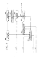
- Fig. 5 shows a general structure of the apparatus.
- the image generation apparatus of the present embodiment has:
- the threshold setting unit 308 increases the threshold by increments of 10 from 10 to 50.
- Fig. 6 is a flowchart showing the operation.
- the threshold setting unit 308 sets the threshold to 10 (see step S30).
- the corresponding point estimator 301 uses the set threshold so as to estimate the presence or absence of the corresponding points and positions thereof between color signal X of image A and color signal X of image B (see step S31).
- the corresponding image assigning unit 302 assigns image information of each position in color signal Y of image B, for which the corresponding point estimator 301 estimates that there is a corresponding point, to color signal Y of image A (see step S32).
- the image interpolator 303 For each position for which the corresponding point estimator 301 estimates that there is no corresponding point, the image interpolator 303 generates image information of color signal Y of image A by means of interpolation using the image information which was already assigned by the corresponding image assigning unit 302 (see step S33).
- the difference generator 306 generates differences between color signal O of image A and color signal Y of image A (see step S34).
- the generated difference summing unit 307 computes the sum of the differences (see step S35).
- the above operation executed by the units from the threshold setting unit 308 to the generated difference summing unit 307 is repeatedly performed while increasing the threshold by increments of 10 up to 50 (see steps S36 and S37).
- the threshold determination unit 309 determines the threshold which produces a minimum value obtained by the generated difference summing unit 307 (see step S38).
- the above-described image generating operation can also be implemented by a computer and a software program.
- a computer program may be provided by storing it in a computer-readable storage medium, or by means of a network.
- image information obtained at a camera position using a color signal image information obtained using another color signal can be used for generating a color signal of the desired image information, thereby reducing degradation in the subjective image quality.
Landscapes
- Engineering & Computer Science (AREA)
- Theoretical Computer Science (AREA)
- Physics & Mathematics (AREA)
- General Physics & Mathematics (AREA)
- Computing Systems (AREA)
- Signal Processing (AREA)
- Multimedia (AREA)
- Geometry (AREA)
- Computer Graphics (AREA)
- Image Processing (AREA)
- Color Television Image Signal Generators (AREA)
- Editing Of Facsimile Originals (AREA)
- Color Image Communication Systems (AREA)
- Processing Of Color Television Signals (AREA)
- Facsimile Image Signal Circuits (AREA)
Applications Claiming Priority (2)
| Application Number | Priority Date | Filing Date | Title |
|---|---|---|---|
| JP2007267541 | 2007-10-15 | ||
| PCT/JP2008/068391 WO2009051064A1 (fr) | 2007-10-15 | 2008-10-09 | Procédé de génération d'image, dispositif associé, son programme et support d'enregistrement du programme |
Publications (2)
| Publication Number | Publication Date |
|---|---|
| EP2202682A1 true EP2202682A1 (fr) | 2010-06-30 |
| EP2202682A4 EP2202682A4 (fr) | 2011-06-01 |
Family
ID=40567331
Family Applications (1)
| Application Number | Title | Priority Date | Filing Date |
|---|---|---|---|
| EP08839078A Withdrawn EP2202682A4 (fr) | 2007-10-15 | 2008-10-09 | Procédé de génération d'image, dispositif associé, son programme et support d'enregistrement du programme |
Country Status (10)
| Country | Link |
|---|---|
| US (1) | US8346019B2 (fr) |
| EP (1) | EP2202682A4 (fr) |
| JP (2) | JP4578567B2 (fr) |
| KR (1) | KR101134665B1 (fr) |
| CN (1) | CN101821768B (fr) |
| BR (1) | BRPI0818593A2 (fr) |
| CA (1) | CA2701890C (fr) |
| RU (1) | RU2440615C2 (fr) |
| TW (1) | TWI397023B (fr) |
| WO (1) | WO2009051064A1 (fr) |
Cited By (1)
| Publication number | Priority date | Publication date | Assignee | Title |
|---|---|---|---|---|
| EP2879372A1 (fr) * | 2013-11-29 | 2015-06-03 | Thomson Licensing | Procédé et dispositif de traitement d'une image brute acquise par une caméra à fonction plenoptique |
Families Citing this family (5)
| Publication number | Priority date | Publication date | Assignee | Title |
|---|---|---|---|---|
| KR101134665B1 (ko) * | 2007-10-15 | 2012-04-09 | 니폰덴신뎅와 가부시키가이샤 | 화상 생성 방법, 장치 및 그 프로그램과 프로그램을 기록한 기록매체 |
| US8849029B2 (en) | 2010-02-26 | 2014-09-30 | Nec Corporation | Image processing method, image processing device and program |
| JP5704984B2 (ja) * | 2011-03-22 | 2015-04-22 | キヤノン株式会社 | 撮像装置 |
| JP6790384B2 (ja) * | 2016-03-10 | 2020-11-25 | 富士ゼロックス株式会社 | 画像処理装置及びプログラム |
| US10147218B2 (en) * | 2016-09-29 | 2018-12-04 | Sony Interactive Entertainment America, LLC | System to identify and use markers for motion capture |
Family Cites Families (23)
| Publication number | Priority date | Publication date | Assignee | Title |
|---|---|---|---|---|
| US4683496A (en) * | 1985-08-23 | 1987-07-28 | The Analytic Sciences Corporation | System for and method of enhancing images using multiband information |
| EP0650299B1 (fr) * | 1993-10-20 | 1998-07-22 | Laboratoires D'electronique Philips S.A.S. | Procédé de traitement des niveaux de luminance dans une image composite et système de traitement d'image appliquant ce procédé |
| US5583665A (en) * | 1995-02-13 | 1996-12-10 | Eastman Kodak Company | Method and apparatus for performing color transformations using a reference image combined with a color tracer |
| KR970049856A (ko) * | 1995-12-30 | 1997-07-29 | 김광호 | 복수개의 라이센서를 갖는 화상독취 장치에서 센서간 거리 보정 방법 및 회로 |
| JP3233601B2 (ja) | 1997-09-25 | 2001-11-26 | シャープ株式会社 | 画像処理装置 |
| DE69833302T2 (de) * | 1997-10-06 | 2006-11-02 | Canon K.K. | Verfahren und Vorrichtung zur Bildsynthese |
| JP3223867B2 (ja) | 1997-11-12 | 2001-10-29 | トヨタ自動車株式会社 | 表示色の色合わせ方法 |
| JPH11242737A (ja) | 1998-02-26 | 1999-09-07 | Ricoh Co Ltd | 画像処理方法及び装置並びに情報記録媒体 |
| FR2782438B1 (fr) * | 1998-08-13 | 2002-01-04 | Pierre Allio | Procede d'affichage autostereoscopique et image autostereoscopique |
| US6269175B1 (en) * | 1998-08-28 | 2001-07-31 | Sarnoff Corporation | Method and apparatus for enhancing regions of aligned images using flow estimation |
| JP4193292B2 (ja) * | 1999-07-02 | 2008-12-10 | コニカミノルタホールディングス株式会社 | 多眼式データ入力装置 |
| US6993167B1 (en) * | 1999-11-12 | 2006-01-31 | Polartechnics Limited | System and method for examining, recording and analyzing dermatological conditions |
| AU2002316067A1 (en) * | 2001-05-02 | 2002-11-11 | Bitstream Inc. | Methods, systems, and programming for producing and displaying subpixel-optimized font bitmaps using non-linear color balancing |
| AU2002357631A1 (en) | 2002-12-20 | 2004-07-14 | Jicoux Datasystems, Inc. | Image synthesizer and program |
| US7474355B2 (en) * | 2003-08-06 | 2009-01-06 | Zoran Corporation | Chroma upsampling method and apparatus therefor |
| JP2005130281A (ja) | 2003-10-24 | 2005-05-19 | Canon Inc | 画像処理システム、画像処理方法及びプログラム |
| RU2267232C1 (ru) * | 2004-06-11 | 2005-12-27 | Федеральное государственное унитарное предприятие Научно-исследовательский институт комплексных испытаний оптико-электронных приборов и систем (ФГУП НИИКИ ОЭП) | Способ преобразования изображений |
| US7483578B2 (en) * | 2005-09-15 | 2009-01-27 | Kabushiki Kaisha Toshiba | Image data decoding apparatus and method |
| KR100809687B1 (ko) | 2006-02-28 | 2008-03-06 | 삼성전자주식회사 | 영상신호에 포함된 잡음을 제거할 수 있는 영상신호처리장치 및 방법 |
| JP2007267541A (ja) | 2006-03-29 | 2007-10-11 | Seiko Epson Corp | フィードバック制御によるモータ制御回路の検査方法、モータ制御回路の検査装置、検査制御プログラム |
| TW200811758A (en) | 2006-08-24 | 2008-03-01 | Realtek Semiconductor Corp | Method for edge detection, method for motion detection, method for pixel interpolation utilizing up-sampling, and apparatuses thereof |
| TWI342157B (en) | 2006-09-19 | 2011-05-11 | Realtek Semiconductor Corp | De-interlacing methods and related apparatuses |
| KR101134665B1 (ko) * | 2007-10-15 | 2012-04-09 | 니폰덴신뎅와 가부시키가이샤 | 화상 생성 방법, 장치 및 그 프로그램과 프로그램을 기록한 기록매체 |
-
2008
- 2008-10-09 KR KR1020107007425A patent/KR101134665B1/ko not_active Expired - Fee Related
- 2008-10-09 JP JP2009538071A patent/JP4578567B2/ja active Active
- 2008-10-09 CN CN2008801114905A patent/CN101821768B/zh not_active Expired - Fee Related
- 2008-10-09 CA CA2701890A patent/CA2701890C/fr active Active
- 2008-10-09 RU RU2010113344/08A patent/RU2440615C2/ru not_active IP Right Cessation
- 2008-10-09 US US12/682,030 patent/US8346019B2/en not_active Expired - Fee Related
- 2008-10-09 EP EP08839078A patent/EP2202682A4/fr not_active Withdrawn
- 2008-10-09 WO PCT/JP2008/068391 patent/WO2009051064A1/fr not_active Ceased
- 2008-10-09 BR BRPI0818593-0A patent/BRPI0818593A2/pt not_active IP Right Cessation
- 2008-10-13 TW TW097139158A patent/TWI397023B/zh not_active IP Right Cessation
-
2010
- 2010-08-20 JP JP2010185571A patent/JP2011028760A/ja active Pending
Cited By (1)
| Publication number | Priority date | Publication date | Assignee | Title |
|---|---|---|---|---|
| EP2879372A1 (fr) * | 2013-11-29 | 2015-06-03 | Thomson Licensing | Procédé et dispositif de traitement d'une image brute acquise par une caméra à fonction plenoptique |
Also Published As
| Publication number | Publication date |
|---|---|
| WO2009051064A1 (fr) | 2009-04-23 |
| TWI397023B (zh) | 2013-05-21 |
| CN101821768A (zh) | 2010-09-01 |
| JP4578567B2 (ja) | 2010-11-10 |
| RU2440615C2 (ru) | 2012-01-20 |
| RU2010113344A (ru) | 2011-11-27 |
| CN101821768B (zh) | 2012-05-30 |
| EP2202682A4 (fr) | 2011-06-01 |
| US20100208991A1 (en) | 2010-08-19 |
| KR20100051744A (ko) | 2010-05-17 |
| CA2701890A1 (fr) | 2009-04-23 |
| BRPI0818593A2 (pt) | 2015-07-21 |
| JPWO2009051064A1 (ja) | 2011-03-03 |
| JP2011028760A (ja) | 2011-02-10 |
| TW200926061A (en) | 2009-06-16 |
| KR101134665B1 (ko) | 2012-04-09 |
| US8346019B2 (en) | 2013-01-01 |
| CA2701890C (fr) | 2013-07-30 |
Similar Documents
| Publication | Publication Date | Title |
|---|---|---|
| US8363985B2 (en) | Image generation method and apparatus, program therefor, and storage medium which stores the program | |
| KR101136506B1 (ko) | 화상 생성 방법, 장치 및 그 프로그램 및 프로그램을 기록한 기록매체 | |
| CN101889452B (zh) | 图像生成装置及图像生成方法 | |
| US20160300337A1 (en) | Image fusion method and image processing apparatus | |
| US8346019B2 (en) | Image generation method and apparatus, program therefor, and storage medium which stores the program | |
| CN110852953B (zh) | 图像插值方法及装置、存储介质、图像信号处理器、终端 | |
| Chung et al. | A low-complexity joint color demosaicking and zooming algorithm for digital camera | |
| CN105049820B (zh) | 图像处理设备、摄像设备和图像处理方法 | |
| JP6332982B2 (ja) | 画像処理装置およびその方法 | |
| US20100079582A1 (en) | Method and System for Capturing and Using Automatic Focus Information | |
| Guttosch | Investigation of Color Aliasing of High Spatial Frequencies and Edges for Bayer-Pattern Sensors and Foveon X3® Direct Image Sensors | |
| CN113781349A (zh) | 图像处理方法、图像处理装置、电子设备及存储介质 | |
| KR101212026B1 (ko) | 적응 크로마키 영상 합성 장치 및 방법 | |
| US8565313B2 (en) | Determining a vector field for an intermediate image | |
| Plataniotis et al. | Data adaptive filters for demosaicking: A framework |
Legal Events
| Date | Code | Title | Description |
|---|---|---|---|
| PUAI | Public reference made under article 153(3) epc to a published international application that has entered the european phase |
Free format text: ORIGINAL CODE: 0009012 |
|
| 17P | Request for examination filed |
Effective date: 20100407 |
|
| AK | Designated contracting states |
Kind code of ref document: A1 Designated state(s): AT BE BG CH CY CZ DE DK EE ES FI FR GB GR HR HU IE IS IT LI LT LU LV MC MT NL NO PL PT RO SE SI SK TR |
|
| AX | Request for extension of the european patent |
Extension state: AL BA MK RS |
|
| DAX | Request for extension of the european patent (deleted) | ||
| A4 | Supplementary search report drawn up and despatched |
Effective date: 20110503 |
|
| RIC1 | Information provided on ipc code assigned before grant |
Ipc: G06T 5/50 20060101ALI20110427BHEP Ipc: G06T 1/00 20060101AFI20090512BHEP Ipc: H04N 1/46 20060101ALI20110427BHEP Ipc: H04N 1/60 20060101ALI20110427BHEP Ipc: G06T 3/00 20060101ALI20110427BHEP |
|
| 17Q | First examination report despatched |
Effective date: 20120425 |
|
| GRAP | Despatch of communication of intention to grant a patent |
Free format text: ORIGINAL CODE: EPIDOSNIGR1 |
|
| INTG | Intention to grant announced |
Effective date: 20160822 |
|
| STAA | Information on the status of an ep patent application or granted ep patent |
Free format text: STATUS: GRANT OF PATENT IS INTENDED |
|
| STAA | Information on the status of an ep patent application or granted ep patent |
Free format text: STATUS: THE APPLICATION IS DEEMED TO BE WITHDRAWN |
|
| 18D | Application deemed to be withdrawn |
Effective date: 20170103 |